Note: Descriptions are shown in the official language in which they were submitted.
096228012074 PATENT
Case No. 910711
207 1 236
CORDLE88 TOO~ BIT 8TORAGE
FIELD OF THE I~v~h.lON
The present invention relates to cordless tools
in general and in particular to a cordless tool that
has a bit storage compartment in the handle thereof
for storing a tool bit to be utilized by the tool.
2071 236
BACRGROUND OF THE lN V ~:N ~ lON
Cordless, battery powered tools are well known in
the art and are used for a variety of functions such
as electric drills, electric screwdrivers, electric
jig saws, and the like. In power tools such as
electric screwdrivers and electric drills, it is
important that the tool or bit to be used by the
cordless device be associated with the device for
quick access. As used hereafter, the term "tool bit"
is intended to mean any type of bit for a battery-
powered tool such as drill bits, screwdriver bits,
jigsaw blades and the like. In elongated cordless
motor-driven electric hand tools such as a
screwdriver, it is difficult to store the tool or bit
on the device itself since the device is generally
cylindrical in shape and has a battery inserted at
one end and the bit-receiving device at the other
end. In such case, the tool or bit itself, such as a
screwdriver having a common screwdriver bit at one
end and a phillips or crosspoint screwdriver bit at
the other end, is generally stored in a container
that is kept separate from the battery-powered tool.
Obviously this is a cumbersome situation at best
since the powered device must not become separated
from the container in which the bit is located. It
would be extremely convenient to have a compartment
on the battery-powered device or tool itself in which
the tool bit could be stored until it is required for
use. However, as stated, with the battery pack
inserted in one end and the bit-receiving device at
the other end and the motor and gear train to drive
-
3 207 1 236
the bit-receiving end in the center, there is little
space left for an enclosure or chamber in which a
tool bit can be inserted for storage purposes.
The present invention overcomes the disadvantages
of the prior art by providing an elongated cordless
motor-driven electric hand tool having an elongated
body portion with a tool bit-receiving means at one
end and a housing at the other end having a battery-
receiving chamber therein. An elongated tool
bit-receiving chamber is formed in the housing above
the battery-receiving chamber and a cover is provided
for the tool bit-receiving chamber that is pivotally
mounted to the housing for opening and closing the
chamber. The cover has an outer shape that conforms
to the outer shape of the housing and matches the
outer contour of the housing in the closed position.
In the preferred embodiment, to minimize the size
of the tool, the housing is oval shaped to create a
space above the battery-receiving chamber and the
tool bit-receiving chamber is in the space above the
battery-receiving chamber. A pivot point is spaced
from one end of the chamber cover for the tool
bit-receiving chamber such that a force applied to
the cover at the one end causes the other end of the
cover to move upwardly from the housing to expose the
tool bit-receiving chamber and allow a tool bit to be
placed therein and removed therefrom. A resilient
spring is placed in the tool bit-receiving chamber
and coupled to the cover for returning the cover to
its closed position when the applied force is
removed. The spring is a leaf spring having one end
rigidly coupled to the bottom of the tool bit-
4 207 1 236
receiving chamber under the outer end of the coverand the other end flexibly positioned under and in
engagement with the inner end of the cover such that
when the inner end of the cover has the force applied
downwardly, the spring in engagement therewith is
deflected and when the applied force is removed the
deflected spring returns to its initial position and
closes the cover.
The battery-receiving chamber has an
unsymmetrical cross-sectional shape with a flat
surface adjacent the tool bit-receiving chamber. It
also has an arcuate section opposite the flat surface
and adjacent an end of the oval shaped housing. A
rechargeable battery pack has an unsymmetrical
cross-sectional shape that matches the unsymmetrical
cross-sectional shape of the battery-receiving
chamber for insertion therein from the one end of the
housing. Thus, with the flat spot on the battery
adjacent the tool bit-receiving chamber, the most
effective use is made of the space in the oval shaped
housing.
Thus it is an object of the present invention to
provide an improved cordless motor-driven electric
hand tool having an elongated body portion with a
tool bit-receiving means at one end and a housing at
the other having a battery-receiving chamber
therein. An elongated tool bit storage chamber is
formed in the housing on one side above the
battery-receiving chamber and has a cover pivotally
mounted to the housing for open and closed
positions. The cover has an outer shape conforming
to the housing shape for matching the outer contour
of the housing in the closed position.
207 1 236
It is another object of the present invention to
form the housing portion of the battery powered tool
with an oval shape to create a space above and/or
below the battery-receiving chamber and placing the
tool bit storage chamber in the space above and/or
below the battery-receiving chamber.
It is still another object of the present
invention to provide a pivot point on the cover of
the tool bit storage chamber that is spaced from one
end thereof such that a force applied to the cover at
the one end causes the other end of the cover to move
upwardly from the housing to expose the tool bit
storage chamber and allow a tool to be placed therein
and removed therefrom.
It is also another object of the present
invention to provide a resilient spring coupled to
the cover of the tool bit storage chamber for
returning the cover to its closed position when the
applied force is removed.
It is yet another object of the present invention
to provide a battery chamber with an unsymmetrical
cross-sectional shape with a flat surface adjacent
the tool bit storage chamber to provide additional
space for the tool bit storage chamber. An arcuate
section is formed on the battery-receiving chamber
opposite the flat surface adjacent to the end of the
oval shaped housing. The rechargeable battery pack
has an unsymmetrical cross-sectional shape that
matches the unsymmetrical cross-sectional shape of
the battery-receiving chamber for insertion therein.
6 207 1 236
S~MMARY OF TH~ lNv~N~ION
Thus the present invention relates to an improved
cordless motor-driven electric hand tool that has an
elongated body portion with a tool bit-receiving
means at one end and a housing at the other end
having a battery-receiving chamber therein. An
elongated tool bit storage chamber is formed in the
housing above and/or below the battery-receiving
chamber. A cover for the tool bit storage chamber is
pivotally mounted on the housing for open and closed
positions and has an outer shape that conforms to the
housing shape for matching the outer contour of the
housing in the closed position.
In the preferred embodiment the housing is oval
shaped to create a space above and/or below the
battery-receiving chamber in which the tool bit
storage chamber is placed. Further, the
battery-receiving chamber has an unsymmetrical
cross-sectional shape with a flat surface adjacent
the tool bit storage chamber for providing additional
space for the tool bit storage chamber. A
rechargeable battery pack has an unsymmetrical
cross-sectional shape that matches the unsymmetrical
cross-sectional shape of the battery-receiving
25- chamber so that it can be inserted therein in only
one direction.
7 2071 236
BRIEF DE8CRIPTION OF THE DRAWING8
These and other objects of the present invention
will be more fully understood in conjunction with a
detailed description of the accompanying drawings in
which like numbers indicate like components and in
which:
FIG. 1 is a top view of the novel elongated
motor-driven electric hand tool;
FIG. 2 is a side view of the novel tool with
the tool bit storage chamber cover in the open
10position;
FIG. 3 is an end view of the novel tool from
the battery-receiving end illustrating the
battery with the flat surface adjacent the tool
15bit storage chamber and illustrating the cover
for the chamber in the open position;
FIG. 4A is an enlarged cross-sectional
detail view of the housing portion of the tool in
which the battery is inserted and illustrating in
20detail the cover for the tool bit storage chamber
in its closed position and the spring for
returning the cover to its closed position when
it is opened;
FIG. 4B is an enlarged cross-sectional view
25of the housing portion of the tool illustrating
the cover for the tool bit storage chamber in its
open position; and
FIG. 5 is a partial cross-sectional view of
a portion of the tool bit storage chamber and the
30cover therefor illustrating the relationship of
the cover and the spring which returns the cover
to its closed position.
8 207 1 236
DETAI~ED DE8CRIPTION OF THE DRAWING8
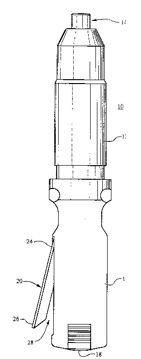
FIG. 1 is a top view of the novel tool 10 of the
present invention. It has an elongated body portion
12 with a tool bit-receiving means 14 at one end and
a housing 16 at the other end. A battery-receiving
chamber 32 (see FIG. 4) is formed in housing 16 for
receiving battery 18. An elongated tool bit storage
chamber 28, seen best in FIG. 2, is formed in the
housing 16 above (but could be below) the
battery-receiving chamber 32 in which battery 18 is
inserted. A cover 20 for the tool bit storage
chamber 28 is pivotally mounted to the housing at
pivot point 22 so that the cover 20 can be opened and
closed. The cover 20 has an outer shape conforming
to and matching the outer contour of the housing 16
when in the closed position, as can be seen in FIG.
5. It will be noted in FIG. 3 that the housing 16 is
oval shaped to create a space above the
battery-receiving chamber 32 (best shown in FIG. 4)
and the tool bit storage chamber 28 is formed in the
space above or on one side of the battery-receiving
chamber 32. The cover 20 has the pivot point 22
spaced from the one end 24 such that a force applied
to the cover at end 24 causes the other end 26 of the
cover 20 to move upwardly from the housing 16 to
expose the tool bit storage chamber 28 as shown in
FIGS. 2 and 4 to allow a tool bit to be placed
therein and removed therefrom. A spring 34 is
coupled to the cover 20 for returning cover 20 to its
closed position when the applied force is removed.
As can be best seen in FIG. 4, a resilient spring
34 is placed in said tool-receiving chamber 28. The
-
9 2071236
outer wall edge on the cover 20 engages the spring 34
at its inner end 40 such that when a force is
supplied to the inner end 24 of the cover 20, outer
wall edge 52 engages portion 40 of spring 34 and
distorts portion 40 by bending it downwardly such
that when the applied force is removed, the spring
portion 40 returns from its distorted position and
forces outer wall edge 52 of inner end 24 of cover 20
upwardly, thus returning the cover 20 to its closed
position. As can be seen in FIG. 4, spring 34 is a
leaf spring having one end 36 rigidly coupled to the
bottom of the tool-receiving chamber 28 under a
portion 46 of housing 16 which may be any desired
material such as plastic or metal. The spring outer
end 36 and outer tip 38 are inserted in slot 42 in a
vertical position and then the spring is tipped to
the rear, thus causing the outer tip 38 of the outer
end portion 36 of the spring to enter slot 44. Thus
the positioning portion 36 of the spring 34 lies
under a projection 46 on housing 16 and is held
rigidly in place. The cover 20 is then engaged in
place. When a force is applied to inner end 24 of
cover 20 to cause the cover 20 to pivot about pivot
25 point 54, the outer wall edge 52 distorts outer end
40 of spring 34 about the end 50 of housing portion
48 on which the spring is resting. As the spring end
40 moves downwardly, the outer wall edge 52 moves to
the position illustrated in FIG. 4B. Thus when the
force is removed from inner end 24 of the cover 20,
the spring 34 forces outer wall edge 52 and thus
inner end 24 of cover 20 upwardly, thus closing the
cover 20.
207 1 236
It will be seen that the rechargeable battery pack 18
has an unsymmetrical cross-sectional shape that matches
the unsymmetrical cross-sectional shape of the battery-
receiving chamber 32 for a close fit therein. Thebattery 18 may be of the type disclosed in commonly-
assigned United States Patent No. 5,122,427 issued
June 16, 1992 and entitled "Battery Pack". It has latch
devices 60 and 62 on the sides thereof for latching the
battery 18 inside the battery-receiving chamber 32 in the
housing 16.
Thus there has been disclosed a novel improved
cordless motor-driven electric hand tool that has an
elongated body portion with a tool bit-receiving device
at one end and a housing at the other end having a
battery-receiving chamber therein. An elongated tool bit
storage chamber is formed in the housing above and/or
below the battery-receiving chamber and has a cover
therefore. The housing is oval shaped to create
additional space above and/or below the battery-receiving
chamber in which the tool bit storage chamber is formed.
The rechargeable battery pack inserted therein has an
unsymmetrical cross-sectional shape that matches the
unsymmetrical cross-sectional shape of the battery-
receiving chamber.
While the invention has been described in connectionwith a preferred embodiment, it is not intended to limit
the scope of the invention to the particular form set
forth, but, on the contrary, it is intended to cover such
alternatives,
11 207 1 236
modifications, and equivalents as may be included
within the spirit and scope of the invention as
defined by the independent claims.