Language selection

Search

Patent 2071377 Summary

Third-party information liability

Some of the information on this Web page has been provided by external sources. The Government of Canada is not responsible for the accuracy, reliability or currency of the information supplied by external sources. Users wishing to rely upon this information should consult directly with the source of the information. Content provided by external sources is not subject to official languages, privacy and accessibility requirements.

Claims and Abstract availability

Any discrepancies in the text and image of the Claims and Abstract are due to differing posting times. Text of the Claims and Abstract are posted:

  • At the time the application is open to public inspection;
  • At the time of issue of the patent (grant).
(12) Patent: (11) CA 2071377
(54) English Title: CLEAN BIDET
(54) French Title: BIDET MONTE SUR W.C.
Status: Expired and beyond the Period of Reversal
Bibliographic Data
Abstracts

English Abstract


In a device to wash the anus area after defecation, it is known that a jet of
water from a nozzle installed under a toilet bowl seat can be used, (US
Patent, 276 2058 & 346 2766). This device consists of a rigid nozzle that
is connected to the water supply line of toilet water tank by means of a
flexible hose and a Tee connection. Tee connection will be installed on
the water tank supply line to branch water supply to the device. A valve
will also be installed between the rigid nozzle and the flexible hose. The
rigid nozzle will be mounted underneath the toilet seat by means of two
clamps. The nozzle discharge opening remains blocked by a simple cover
when the device is not in use and it is exposed only when the water valve
is turned open for washing.


Claims

Note: Claims are shown in the official language in which they were submitted.

CLAIMS
The embodiment of the invention in which an exclusive property or
privilege is claimed are defined as follows:
1 ) A cleaning bidet that is to be installed underneath a toilet seat for
washing anus area after defecation, comprising of;
- a rigid nozzle that is bent at two ends in opposite directions with a
straight section in the middle and said straight section is attached to the
underneath toilet seat by means of clamps that allow the nozzle to rotate
partially around its longitudinal axis, while one side bend of about 90
degrees of said nozzle forms its discharge opening and located under toilet
seat, the other side bend of said nozzle of about 60 degrees, is located
outside the toilet and is connected to
-a valve located outside the toilet bowl and the other end of said valve is
connected to a flexible tube or hose, as such that the hose connects said
valve and the nozzle to the water supply line by means of ordinary pipe
and tube fittings such as Tee connection,
-a cover affixed also underneath the toilet seat in a position that will cover
said discharge opening of the nozzle when the discharge bend moves
upward and since two bends of the nozzle are in opposite directions, the
weight of the valve and hose moves the discharge bend upward, resting
said discharge opening against the cover until the valve is lifted and
opened by hand to direct the water jet in proper direction for washing.
2) A device as defined in claim 1 in which the cover is replaced by a
flapper type cap, connected to the nozzle discharge opening as such that
said flapper cap rests on the opening of the nozzle discharge by its own
weight and prevents entry of any substance into the discharge opening of
the nozzle but when said valve is opened by the user, the flow and
pressure of water moves the flapper cap open and water jet will clean the
intended area.
3) A device as defined in claims 1 or 2 in which tempered water by
means of a mixture of cold and warm water is used for washing.

Description

Note: Descriptions are shown in the official language in which they were submitted.


SPECIFICATION 2 0 713 7 7
This invention relates to a device that is to be mounted on toilets forwashing the regions of anus by means of a jet of water.
In many parts of Asia water is used to wash oneself after defecation byuse of the special pitchers. Use of a pitcher is not practical on the
western toilets. Use of bidet on the other hand, takes extra room, it is
expensive and requires one to move from toilet to bidet in an awkward
situation. Use of toilet paper is relatively expensive, never truly cleans,
often makes hands dirty and is a waste of the natural res~ces.
The previous inventions and improvements to those in~lons that relate
to the use of water jet or spray have at least one of the following
fundamental problems.
1 ) The previous inventions were complicated and as a result would be
expensive and difficult to install by the buyers themselves.
2) The nozzle openings were not protected against an occasional splash
and entrance of dirty droplets or particles during urination, excretion and
toilet flushing.
3) The direction of water jet or spray was fixed in some, making them
unadjustable for use by people of different hip sizes and posture that
would require different water jet angles.
I have found that all those disadvantages may be overcome by making thedevice nozzle from a single rigid metallic or plastic tube that is mounted
underneath the toilet seat by means of clamps or pipe straps. A valve is
connected to the end of said rigid tube and a flexible tube or hose
connects the said valve to the water supply by means of a Tee
connection .
DESCRIPTION OF DRAWINGS
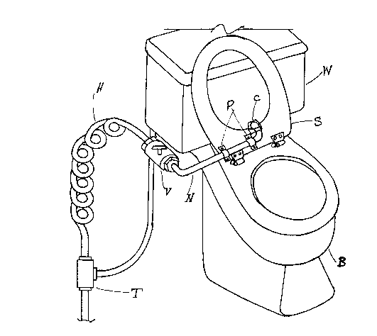
Figure 1 shows a perspective view of the invention installed on a toilet
when the toilet seat is lifted in vertical position. Water supply is provided
to the device from the water line to the water tank. The straight section
of the nozzle (N) is mounted underneath the toilet seat (S) by means of
clamps or pipe straps (P).
Figure 2 shows the nozzle and the related portion of a toilet seat whenthe toilet seat is put down in its normal horizontal position.
Figure 3 is a perspective view of the invention mounted on a toilet with
the toilet seat being put down on the toilet bowl.
Figure 4 is a view of the nozzle (N) while being used and the related
section of the toilet seat (S) and the nozzle discharge opening cap (C).
Water is shown to flow out of the discharge end of the nozzle.

2071377
Figure 5 is a side view of a portion of the toilet seat (S), discharge section
of the nozzle (N) and a flapper type cap (F).
Figure 6 shows three views of said nozzle cover in Figure 4.
DETAILED DESCRIPTION OF THE INVENTION
Referring to Figure 1, this device consists of a nozzle (N), a valve (V), a
flexible tube or hose (H), a Tee connection (T), two pipe straps or clamps
(P) and a nozzle cover (C). The nozzle is made from metallic or rigid
plastic tube that is bent at two ends and has a straight section in the
middle, Figures 1 &3. The discharge end of the nozzle is bent in two
planes as shown on Figure 4, to direct the flow of water in a proper
direction and the other end of the nozzle is bent as per Figure 3 in an
opposite direction. The straight portion of the nozzle is mounted under the
flat lower side of the toilet seat by two pipe straps or clamps (P) as shown
on Figure 1. The clamps or pipe straps do not hold the straight portion of
the nozzle tight and as a result the nozzle can partially rotate in these pipe
straps or clamps. The other end of the nozzle is connected to a valve
such as a ball valve by soldering or mechanical means such as barb or
compression type connectors. The hose (H) connects the valve to the Tee
connection by ordinary connectors such as barb or compression type
connectors. The Tee (T) connection is installed on the water supply line to
the toilet water tank, usually a 3/8" tube, by ordinary connections such
as compression type connectors.
As it is seen on Figure 3 The weights of the valve and hose make the
nozzle rotate until its discharge opening rests against the cover (C) which
is affixed to the toilet seat lower side as well. Therefore as it is shown on
Figure 2, the opening of the nozzle remains covered when the seat is put
down on toilet bowl. This simple design protects the nozzle opening
against entry of any dirty substance, that otherwise makes the device
unacceptable to users.
The user lif.s the valve to move the nozzle discharge opening downward
and off from its cover, then turns the valve open and moves the valve
slightly up and down which in turn controls the direction of the water jet
to wash the intended area. Two sides of the nozzle cover (C) in Figure 4
keep the nozzle from sliding off from seat center and the bottom side limits
the nozzle from being moved too low. By the amount that the valve is
opened and moving it up and down, the water jet flow and direction are
controlled. The user would easily feel the right flow and direction for a
comfortable and effective wash.
Instead of said cover a flapper type cap as per Figure 5 can be installed on
the nozzle that remains closed by its own weight but moves open by the
water flow when the valve (V) is opened.
The water supply to the device can be made tempered by the following
design: Supply of hot water will be piped to where the Tee connection (T)
is shown on Figure 1. Hot water pipe line is usually available in a
bathroom. An automatic temperature control Tee connection that is now
2 ~

207~377
available in market by various manufacturers, then will be installed
between the original T connection (T) and the Hose (H). cold water to the
automatic temperature control Tee will be supplied by the original Tee
connection and hot water to the automatic temperature control Tee will be
supplied from said new hot water line. These said automatic temperature
control Tee connections usually are equipped with a temperature control
setting that prevents the outlet water temperature to exceed the set
temperature .

Representative Drawing
A single figure which represents the drawing illustrating the invention.
Administrative Status

2024-08-01:As part of the Next Generation Patents (NGP) transition, the Canadian Patents Database (CPD) now contains a more detailed Event History, which replicates the Event Log of our new back-office solution.

Please note that "Inactive:" events refers to events no longer in use in our new back-office solution.

For a clearer understanding of the status of the application/patent presented on this page, the site Disclaimer , as well as the definitions for Patent , Event History , Maintenance Fee  and Payment History  should be consulted.

Event History

Description Date
Inactive: IPC deactivated 2016-01-16
Inactive: IPC assigned 2015-08-17
Inactive: First IPC derived 2006-03-11
Time Limit for Reversal Expired 1997-06-16
Letter Sent 1996-06-17
Grant by Issuance 1995-03-14
Application Published (Open to Public Inspection) 1993-12-17
All Requirements for Examination Determined Compliant 1992-06-16
Request for Examination Requirements Determined Compliant 1992-06-16

Abandonment History

There is no abandonment history.

Owners on Record

Note: Records showing the ownership history in alphabetical order.

Current Owners on Record
PARVIZ PEZESHK ZAD
Past Owners on Record
None
Past Owners that do not appear in the "Owners on Record" listing will appear in other documentation within the application.
Documents

To view selected files, please enter reCAPTCHA code :


To view images, click a link in the Document Description column. To download the documents, select one or more checkboxes in the first column and then click the "Download Selected in PDF format (Zip Archive)" or the "Download Selected as Single PDF" button.

List of published and non-published patent-specific documents on the CPD .

If you have any difficulty accessing content, you can call the Client Service Centre at 1-866-997-1936 or send them an e-mail at CIPO Client Service Centre.


Document
Description 
Date
(yyyy-mm-dd) 
Number of pages   Size of Image (KB) 
Cover Page 1995-03-14 1 15
Description 1995-03-14 3 119
Abstract 1995-03-14 1 18
Claims 1995-03-14 1 41
Drawings 1995-03-14 3 51
Representative drawing 1998-10-02 1 15
Fees 1995-06-09 3 136
Fees 1994-09-02 1 36
Examiner Requisition 1993-01-04 2 68
Prosecution correspondence 1993-03-29 2 56
Examiner Requisition 1994-05-27 2 107
Prosecution correspondence 1994-07-27 1 17
Prosecution correspondence 1994-09-29 2 23
PCT Correspondence 1995-01-09 1 27
Courtesy - Office Letter 1992-12-15 1 46
Courtesy - Office Letter 1992-12-01 1 40
Courtesy - Office Letter 1992-11-12 1 20
Prosecution correspondence 1992-11-24 5 176