Note: Descriptions are shown in the official language in which they were submitted.
CA 02071557 1992-06-18
USE OF ITERATION TO IMPROVE THE CORRECTION OF AGC
DEPENDENT CHANNEL-TO-CHANNEL GAIN IMBALANCE
BACKGROUND
The present invention relates generally to automatic gain control (AGC)
circuits,
and more particularly, to methods and apparatus that erect AGC-dependent gain
imbal-
ance using iteration in such AGC circuits.
In certain radar guidance systems, the amplitudes of the sum {E) and delta {0)
signals received at its antenna are processed to derive the angle of a radar
return relative
to the antenna boresight. It is common in such systems to combine the sum and
delta
signals into two channels (E + O) and (E - d) after their frequencies have
been trans-
lated to an intermediate frequency. These two channels are independently
processed,
and then combined to recover the sum and delta amplitudes, which are used to
produce
the angle of the return.
Any hardware induced gain difference between the two channels results in the
calculated angle being corrupted by a bias, which degrades the performance of
the
guidance system. One possible hardware source of gain imbalance is a
differential
change to the gain of each channel as a result of a change to its automatic
gain control
(AGC) circuit. A conventional technique to correct for this occurrence is to
measure
channel-to-channel gain imbalance versus AGC during a calibration cycle, and
to use
these measurements as commands that correct the mismatch.
Since processing of the amplitudes of sum and delta channels yield the angle
information, they must be accurately maintained throughout the processing
chain. This
requires that the gains of the E + D and ~ - 0 channels are matched during the
time
period when sum-delta processing takes place. Any mismatch between the gain of
the
i
CA 02071557 1992-06-18
2
~ + D channel and the gain of the ~ - D channel results in a bias error in the
calculation
of the angle of the return. It is the function of "delta automatic gain
control" (AAGC)
circuitry in such systems (comprising a DAGC caontroller and AAGC controlled
ampli-
fiers) to measure the channel-to-channel gain imbalance, and to automatically
correct it
before angle processing begins.
More particulariy, in some radar systems, large changes in channel-to-channel
gain result from changes in the overall system gain due to automatic gain
control
(AGC). One technique used to compensate for mis in to characterize the
required
~AGC change needed to balance the two channels for any change in AGC, so that
the
change in ~AGC may be predicted once the change in AGC is known. This
characteri-
zation is done during a period of time dedicated to system calibration. A test
signal is
applied to the guidance system which has been configured such that the delta
channel
amplitude is zero. This results in the E + O and E - O channels containing
only the
sum inforn~ation. Thus, any difference in the amplitudes of the signals
between the
two channels is due to channel-to-channel gain imbalance. This imbalance is
measured
for various levels of AGC (each level consistently larger or smaller than the
last), with
the eAGC circuit removed from the processing chain so that it does not provide
chan-
neI-to-channel gain balancing. Each imbalance measurement is the level that
the ~AGC
must achieve in the hardware to balance the channel-to-channel gains for that
particular
AGC value.
In this way, a table is generated and staved in the AAGC controller that
consists
of the AGC points where the measurements ware taken, and the slopes of these
mea
surements between consecutive AGC points. For example, if at AGC level AGCn
the
channel-to-channel gain imbalance is ~,, and at AGCp + 1, the imbalance is ~ +
1,
then the table value for AGCt, is: (~,.~I - A~ + (AGCn+1- AGC,~. During angle
processing, if a change in AGC is to occur, the beginning and ending values of
AGC
along with the current value of the AAGC command are used in conjunction with
the
information in this table to derive the new AAGC command which compensates for
the
predicted change in channel-to-channel gain caused by the change in AGC.
However, although adequate performances achieved with this conventional
approach, it has been found that it is possible to achieve better performance
utilizing the
principles of the present invention.
SUMMARY OF THE INVENTION
In order to improve the performance of AGC control circuitry for use in a mis-
sile radar guidance system, or the like, the present invention provides for a
method and
apparatus that uses iteration to achieve a better prediction for the values of
the com-
CA 02071557 1992-06-18
manila need to balance the gains of :the ~ + a and E - a chapels of the
missile radar
guidance system, when an imbalance occurs due to a change caused by the AGC
cir-
cuitry. 'The present invention impaoves the conva~tional texhruque that
measures chan-
nel-to-channel gain imbalance versus AGC during calibration. This calibration
occurs
when the missile is activated' typically during a puredeterminod calibration
period The
pit im~entio~n employs an inoprovod method of taking these measureoaents, and
these measuremextts are them used as commands that correct the mismatch during
mis-
sile flight so that residual exror is minimized and more aocuta~ guidance is
achieved.
A predetermined cornection curve is gex~esaned (at the factoay) that
represents the
~0 "average" (frac all systenos manufactm~ed do a partia~3ar speciscatian)
oo~l input to
the eAGC amplifiers required w achieve the commanded gain. This c~oaroction
curve is
used for all such missiles, regardless of individust hardware differeucos.
Consequent-
ly, for missiles that are not mat~chexl to the "average" ion curve, guidan~x
arses
are generated and applied to the missile; guidance system that are particular
for each
missile; system. The present systean and method uses iteration to deaeimine a
set of
revised input values that are applied as inputs to the "averagd' coarocxion
curve that
adjust the output derived from the correction curve to mote ac~uately contras
the
eAGC amplifiers This results in proper guidance signals being applied to the
missile.
In the present system and method, during system calibration which occurs at
missile system turn-on, a eAGC controller is used to compute channel-roo-
chann~el gain
correction factors which are stored in a loolCUp table and then used as inputs
to an
amplifier control cirarit incorporating the "average" oomation curve to prod~e
inputs
to eAGC controlled amplifiers. The values stored in the lookup table
appropriately
modify the output of the amplifier c~oi circuit bo vompmsate fat' t>ye actual
eAGC
amplifier hardware that is in the: missile. The impmvcd ~axtiaa~ pa~ovided by
the
p~sent imrent~on results in the channel-to-d~annci gain cordon applied to the
eAGC
amplifiers equalling the desired (cohmoandexl) value. Tha~efaa~e, true
correction is
achieved ~ spite of the diffencc~ces betwexn con~ecrion signals that would
normally be
generated by the "average" c~ection curve. Th~ef~, the presem mood and apps
rates more accurately compcnsaties for manufacturing erroa~s in the p~duc~On
of the
g~~ sy~ h~dware, and particularly the gain control amplifiers.
The present system and method is implemented by measuring the gain imbal
sure at pa~edet~ed AGC points (typically fend) during sy~m ~libmtioa A ust
signal is applied to the guidancx system and the system is configured such
that the delta.
channel amplitude is zero. This results in the E + a and E - A channels
e~taining
only sum information. Thus, any difference in the amplitudes of the signals
between
the two channels is due to channel-to-charnel gain imbalance.
CA 02071557 2004-11-29
4
For each particular AGC point the input value applied to the amplifier control
circuitry is iterated a predetermined number of times until a desired level of
gain
imbalance (and hence ~AGC correction) is achieved for that value of AGC. The
iterative process iterates and adjusts the input values to the amplifier
control circuitry
such that the correction signal values provided to the DAGC amplifiers is
sufficient to
properly correct for the gain imbalance. The newly determined DAGC points are
stored in the lookup table for use by the missile during flight. DAGC values
other
than the computed DAGC points are determined by interpolation.
More specifically, to find the DAGC values, during system calibration, the
channel-to-channel gain mismatch is found for each possible given value of
AGC.
This measured imbalance is then transformed using a DAGC function and applied
to
the DAGC amplifiers. The resulting gain imbalance is measured and this value
is
added to the originally measured value. This iterated value is again
transformed and
applied to the DAGC amplifiers, and again the imbalance is measured, and is
added to
the modified first measurement. This procedure is repeated until a
satisfactory level
of error is measured which produces the proper correction factor that balances
the
channel-to-channel gains for that specific value of AGC.
The improved apparatus of the present invention comprises a ~AGC controller
that is used in conjunction with test signal generation circuitry that is
employed
during missile system calibration. The DAGC controller contains a lookup table
that
stores the modified gain correction signals determined using the above method,
and
an amplifier control circuit that contains the correction curve that is used
to apply
control signals to the DAGC amplifiers in response to the derived gain
correction
signals. These correction signals are applied to the DAGC amplifiers by way of
the
amplifier control circuitry during operation of the guidance system to achieve
better
performance.
CA 02071557 2004-11-29
4a
Accordingly, in one aspect of the present invention there is provided in a
radar
guidance system for use in a missile, the radar guidance system having
automatic gain
control (AGC) circuitry that comprises a controller having a lookup table, and
wherein the controller is coupled to controllable gain control amplifiers, a
method of
balancing the gains of E + 0 and E - ~ channels of the radar guidance system
when an
imbalance occurs due to a change caused by the controllable gain control
amplifiers,
said method comprising the steps o~
activating the missile and radar guidance system;
measuring the gain imbalance at predetermined AGC points during radar
guidance system calibration subsequent to activation of the missile and
providing a set
of correction factors indicative thereof;
iterating the correction factors by applying the correction factors to the
controllable amplifiers to determine a final set of correction factors that
balances the E
+ 0 and E - 0 channels of the radar guidance system for each possible AGC
value;
storing the final set of correction factors in the lookup table;
applying the final set of correction factors to the controllable amplifiers in
response to changes in the AGC values to more accurately guide the missile.
According to another aspect of the present invention there is provided in a
radar guidance system for use in a missile, the radar guidance system having
automatic gain control (AGC) circuitry that comprises a controller having a
lookup
table, and wherein the controller is coupled to controllable gain control
amplifiers, a
method of balancing the gains of E + 0 and E - 0 channels of the radar
guidance
system when an imbalance occurs due to a change caused by the controllable
gain
control amplifiers, and wherein the channel-to-channel gain correction
provided to the
controllable amplifiers substantially equals a desired value, said method
comprising
the steps of:
activating the missile and radar guidance system;
measuring the gain imbalance at a plurality of predetermined AGC points
during radar guidance system calibration subsequent to activation of the
missile and
computing a set of correction factors indicative thereof;
iterating the correction factors by applying the correction factors to the
controllable amplifiers a predetermined number of times to determine a final
set of
CA 02071557 2004-11-29
4b
correction factors that balances the E + 0 and E - 0 channels of the radar
guidance
system for each possible AGC value;
storing the final set of correction factors in the lookup table;
applying the final set of correction factors to the controllable amplifiers in
response to changes in the AGC values to more accurately guide the missile.
According to yet another aspect of the present invention there is provided in
a
radar guidance system having automatic gain control (AGC) circuitry that
comprises a
controller having a lookup table, and wherein the controller is coupled to
controllable
amplifiers, a method of balancing the gains of E + 0 and E - O channels of the
radar
guidance system when an imbalance occurs due to a change caused by the AGC
circuitry, said method comprising the steps of
activating the missile and radar guidance system;
calibrating the system by measuring gain imbalance value between the E + 0
and E - 0 channels for a selected one of a plurality of predetermined AGC
input
values;
computing a gain correction factor for the selected predetermined AGC input
value and applying the gain correction factor to the controllable amplifiers;
remeasuring the resulting gain imbalance value in response to the applied gain
correction factor and adding this value to the previously measured gain
correction
factor;
repeating the computing and remeasuring steps for the selected AGC input
value until a desired level of error is measured, thus providing a gain
correction factor
that balance the channel-to-channel gains for the selected AGC value; and
repeating the above calibrating, computing, and remeasuring steps for each
AGC input value of the plurality of predetermined AGC input values to produce
a
final set of gain correction factors, and wherein the channel-to-channel gain
correction
provided by the controllable amplifiers in response to the final set of
correction
factors substantially balances the E + 0 and E - 0 channels of the radar
guidance
system;
storing the final set of correction factors in the lookup table; and
applying the final set of correction factors to the controllable amplifiers in
response to changes in the AGC values during missile flight to more accurately
guide
i i
CA 02071557 2004-11-29
4c
the missile.
BRIEF DESCRIPTION OF THE DRAWINGS
The various features and advantages of the present invention may be more
readily understood with reference to the following detailed description taken
in
conjunction with the accompanying drawings, wherein like reference numerals
designate like structural elements, and in which:
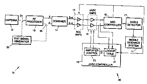
FIG. 1 is a block diagram of an AGC circuit for use with a missile guidance
system that incorporates the principles of the present invention;
FIG. 2 is a graph of signal input to DAGC amplifiers versus the command
from a DAGC controller in the circuit of FIG. 1;
FIG. 3 is a graph of applied correction signal versus commanded correction of
the channel-to-channel gain implemented in the circuit of FIG. 1; and
CA 02071557 1992-06-18
s
FIG. 4 illustrates a flow chart representative of one method in accordance
with
the principles of the present invention.
DETAILED DESCRIPTION
Referring to the drawing figures, FIG. 1 is a block diagram of a radar system
incorporating an AGC circuit 20 for use with a missile guidance system 11 that
incorporates the principles of the present invention. The radar system 10
comprises an
antenna 12 that is coupled to an RF processor 13 that is adapted to produce
sum (E)
and delta (D) output signals. The sum and delta output signals are coupled to
a com-
10 biner 14 that produces E + D and E - 0 output signals.
The E + D and ~ - D output signals arc serially coupled through AGC-control-
led amplifiers 15 and eAGC-controlled amplifiers 16 through an AGC controller
19 to
an amplitude angle detector 17. Output signals from the DAGC controlled
amplifiers
16 are coupled to a ~AGC controller 18 which provides feedback control signals
to the
AAGC controlled amplifiers 16. Output signals from the DAGC controlled
amplifiers
16 are coupled to an AGC controller 19 which provides feedback control signals
to the
AGC controlled amplifiers 15, and AGC commands to the ~AGC controller 18.
Output signals from the angle detector 17 are coupled to the missile guidance
system
11, which output signals are adapted to steer the missile.
The DAGC controller 18 includes a lookup table 21 that comprises a memory
device, and an amplifier control circuit 22. The amplifier control circuit 22
contains
circuitry which applies input signal to the dAGC ~ntmlled amplifiers 16 in
response
to input signal derived from the lookup table 21. A test signal generator 23
is coupled
to the input to the RF processor 13 and to the output thereof such that a test
signal can
be applied to ~e RF processa~r 13 and such that the combiner 14 is configured
such that
the applied delta channel amplitude is zero. This is accomplished in a
conventional
manner, herein represented by means of switches 24, 25.
The present method and apparaws are used to compensate for the changes in
system channel-to-channel gain due to changes in the automatic gain control
circuitry.
In the prior art system, instantaneous AGC changes cause large angle jumps and
there-
fore cause tracking problems for the missile guidance system 11. The present
imren-
tion is adapted to alleviate these tracking problems in the following manner.
The pre-
sent method characterizes the required ~AGC change needed to balance the E + O
and
E - O channels for any change due to AGC related errors, so that the change in
AAGC
is predicted once the change in AGC is known. This characterization is done
during
calibration of the radar system 10 at the time that the system 10 and missile
11 are acti-
vated. A test signal is applied to the guidance system at the input to the RF
processor
CA 02071557 1992-06-18
.rte
13 and the combiner 14 is configured such that the D channel amplitude is
zero. This is
accomplished by applying the test signal from the test signal generator 23
that employs
the switches 24 w interrupt the signal line between the antenna 12 and the 1tF
processor
13 and that controls the signal outputs from the RF processor using the switch
25.
This results in the ~ + A and E - ~ channels containing only sum information.
Thus, any diffe~e in the amplitudes of the signals between the two channels is
due
to channel-to-channel gain imbalance. This imbalance is measured fag various
levels of
AGC (each level consistently lager or smaller than the last), with the AAGC
circuit out
of the circuit so as not to provide channel-to-channel gain balancing.
Typically fom
points are measured. Fa~ch imbalance measurement is the level that the aAGC
c~l-
ler 18 must apply to the ~1AGC amplifie=s I6 is order to balance the channel
to-channel
gains for that particular AGC value.
In this way, the lookup table 21 is generated and stoned in tlx AA.GC
controller
18 that comprises the AGC points where the measurements were taken, and the
slopes
of these measurements between consecutive AGC paants. Foe' example, if at AGC
level AGCa the channel-to-channel gain imbalance is Vin: ~ at AGCn + i, the
imbal-
ance is A~ + i, then the table value for AGCn is: (A~i - t1n}~(AGCn.~.1- AGCY.
Dur-
ing angle processing, if a change in AGC occurs. the beginning a~ auiing
values of
AGC along with the current value of the aAGC wand are used in conjunction with
the information in the lookup table 21 to derive a new DAGC command that
compere
sates for the pmcdicted change in channel-to-channel gain caused by the charge
in AGC.
In the present method the gain imbalan<x is measured at paticular AGC points
during radar system calibration, and these measurements are also used w
detenoQine,
through iteration, the value, which when transformed by the AA.GC function and
applied to the ~iAGC-cantrolkd amplif~rs 16 will eomp~satc f~ the , and
produce a relatively small chancel to-channel gain imbalance. To fmd the value
of the
~AGC function, during system calibration, the channel to-channel gain mismatch
is
found for a given value of AGC. This nyeasrmed imbalance is then transformed
by the
DAGC function and input to the AAGC controlled amplifiers 1G. The resulting
gain
imbalance is remeasured and this value is added to the ariguial measummetu.
This
iteration is again transfornod and i~ut to the AAGC controlled anplifias 16,
and
again the imbalance is ~ and is now added. to the modified first measurement.
This procedin~e is repeated until a satisfactory level of earn is yielding the
value of the pmoper input to the ~AGC function which will balance the c~ant~l-
to-
channel gains for that value of AGC.
CA 02071557 1992-06-18 - -.
7
FIG. 2 is a graph of signal input to DAGC controlled amplifiers lb versus the
command from the lookup table 21 in the AAGC controller I 8 in the radar
system 10 of
FIG. 1 that is needed to balance the channel-to-channel gains. In the present
method,
the AAGC controller 18 transfomos the desired channel-to-channel gain
correction
using the AAGC function which produces an input roe the AAGC amplifiers 16
that
results in the channel-to-channel gain correction. The gain correction
provided by the
DAGC controller 18 and DAGC amplifiers 16 substantially equals the desired
(com-
mended) value.
FIG. 3 is a graph of AAGC correction signal versus commanded AAGC correc-
Lion of the channel-to-channel gain in the circuit 20 of FIG. 1. These curves
are shown
as linear for the purposes of simplicity, and are not to be considered as
actual results.
Curve 28 shows a non-ideal situation wherein the correction value is
proportional to the
commanded correction value by a factor "B", wherein 0 S B S 1. C rove 2b shows
the
ideal situation wherein the achieved connection is equal to the commanded
correction,
i.e. B =1. Curve 27 shows a situation wherein the achieved correction
approaches the
ideal value of the commanded correction as more iteratia~ns are made using the
method
of the present invention.
FIG. 4 illustrates a flow chart representing one method 30 in accordance with
the principles of the present invention. The method 30 is used in the radar
guidance
system 10 employed in the missile 11, for example. The radar guidance system
10 has
delta automatic gain control (dAGC} circuitry comprising the controller 18
having the
lookup table 21, and wherein the controller 18 is coupled to the controllable
gain con-
trol amplifiers lb. The method 30 is a method of balancing the gains of ~ + d
and ~ -
~ channels of the radar guidance system 10 when an unbalance ocacurs due to a
change
caused by the AGC circuitry. The method 30 comprises the following steps.
Activat
ing the missile and radar guidance syst~ 10, as is indicated by box 31.
Measuring the
gain imbalance at predetermined AGC points during radar guidance system
calibration,
as is indicated by box 32, and providing a set of c~r~ectio~n factors
indicative thereof, as
is indicated by box 33. Iterating the correction factors by applying the
correction fac-
tons to the controllable amplifiers 16 to determine a final set of correction
factors that
balances the E + A and E - 0 channels of the radar guidactce system 10 for
each possi-
ble AGC value, as is indicated by box 34. Storing the final set of caarection
factors in
the lookup table 21, as is indicated by box 35. Applying the final set of
~tion
factors to the controllable amplifiers 16 in response to changes in the AGC
values to
more accurately guide the missile 11, as is indicated by box 36.
CA 02071557 1992-06-18
,
8
An example of the present method is presented below. Assume that the aAGC
function plus the hardware error achieves 8c channel-o~-channel gain (0 5 B S
1) when
it receives an input c. The aroc betvueen the achieved channel-w-channel gain
and the
commanded channel-to-channcl gain is then c - Be or c(I - B). 1f c is the
channel imbal-
S ance at a particular AGC, -and is used as a command to the ~AGC ampliBas I6
when
the AGC commarud value reaches this value, the channels will s~l have an
imbalardce
equal to c(1- B). I~ however, during system calibration, the connmar~d
required to
balance the channels is allowod to ixza~ the error addeved when using this
iterated
command value will be less than that achieved without it. The iterations and
the result
IO ing channel balancing errors. ~ as follows in Table I:
TABLE 1
~Vo. Co~,n, Error
1 0 c
2 c c Bc = c(1-B) .
IS 3 c+c(1-B) = 2c-Bc c-2Bc+~c = c( 1-2B+B~ = c(1-B~
4 2c-Bc+c(1-2B+B~ = 3c-38c+B2c o-3Bc+3BZc B~c =c(1-3B+382+B~)
- c(1-B~
3c-3Bc+Bzc+c(1-3B+3B2-B3c)+ o-4Bc+6B~48~C+B4c
c(1-3$+3B2-83c) = c(1-4B+6Bz-4B3+B~)
20 = 4c-6Bc+482c-B3c = c(1-B~
Thus, for the k~ command, the error is c(1-B~ 1.
The following Table 2 compares the errors for no iterations versus four itera-
tions for various values of B.
TABLE 2
25 B Error (no iterations) Error (four iterations)
c(1 Bl c(1-B14
0.0 c c
0. I 0.9c 0 656c
0.2 0.8c 0 410c
30 0.3 0.7c 0.240c
0.4 0.6c 0.130c
0.5 O.Sc 0.065c
0.6 0.4c p OZ~
0.7 0.3c 0.00$lc
35 0.8 0.2c 0.001 be
0.9 O.lc O.OOOIc
i.0 0.0 0.0
CA 02071557 1992-06-18
a~
Thus there has been descn'bed a new and improved AGC correction cinvit and
method for use in a missile radar guidance system which corrects AGC-dependent
channel-to-channei gain imbalance by using iof gain cor~octi~oa fsctocs. It is
to
be understood that the above-described aobodiment is merely illustrative of
some of the
many specific embodiments which repraa~t applications of the principles of the
present
invention. Clearly, numerous and other arrangements can be readily devised by
those
stalled in the art without departing ~ the scope of the invent.