Language selection

Search

Patent 2071927 Summary

Third-party information liability

Some of the information on this Web page has been provided by external sources. The Government of Canada is not responsible for the accuracy, reliability or currency of the information supplied by external sources. Users wishing to rely upon this information should consult directly with the source of the information. Content provided by external sources is not subject to official languages, privacy and accessibility requirements.

Claims and Abstract availability

Any discrepancies in the text and image of the Claims and Abstract are due to differing posting times. Text of the Claims and Abstract are posted:

  • At the time the application is open to public inspection;
  • At the time of issue of the patent (grant).
(12) Patent: (11) CA 2071927
(54) English Title: COIL ASSEMBLIES
(54) French Title: BOBINES
Status: Expired and beyond the Period of Reversal
Bibliographic Data
(51) International Patent Classification (IPC):
  • H01F 27/06 (2006.01)
  • H01F 27/02 (2006.01)
  • H01F 27/29 (2006.01)
(72) Inventors :
  • SALVAGE, RICHARD JAMES (United Kingdom)
  • HARRINGTON, STEVEN JOHN (United Kingdom)
  • POWELL, DEREK WILLIAM (United Kingdom)
(73) Owners :
  • KNOWLES ELECTRONICS CO.
(71) Applicants :
  • KNOWLES ELECTRONICS CO. (United Kingdom)
(74) Agent: OSLER, HOSKIN & HARCOURT LLP
(74) Associate agent:
(45) Issued: 1999-08-03
(86) PCT Filing Date: 1990-11-26
(87) Open to Public Inspection: 1991-06-22
Examination requested: 1997-06-06
Availability of licence: N/A
Dedicated to the Public: N/A
(25) Language of filing: English

Patent Cooperation Treaty (PCT): Yes
(86) PCT Filing Number: PCT/GB1990/001828
(87) International Publication Number: WO 1991010243
(85) National Entry: 1992-06-16

(30) Application Priority Data:
Application No. Country/Territory Date
8928899.7 (United Kingdom) 1989-12-21

Abstracts

English Abstract


This invention relates to coil assemblies and in particular, but not exclusively, to such assemblies for acoustic transducers.
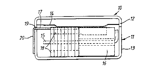
Thus a transducer (10) includes a case (11) in which is located a coil (16) mounted on a flexi-circuit, which locates the coil (16) for
its assembly handling and which allows various configurations within the case (11). A method of winding the coil (16) and mounting
it on the carrier (17) is also described.


French Abstract

Cette invention se rapporte à des montages de bobines et en particulier, mais pas exclusivement, à des montages de transducteurs acoustiques. Ainsi un transducteur (10) comprend un boîtier (11) dans lequel se trouve une bobine (16) montée sur un circuit souple qui reçoit la bobine (16) en vue de sa manipulation lors de son montage et qui permet des configurations diverses à l'intérieur du boîtier (11). On décrit également une méthode permettant de bobiner l'enroulement (16) et de le fixer sur le support (17).

Claims

Note: Claims are shown in the official language in which they were submitted.

THE EMBODIMENTS OF THE INVENTION IN WHICH AN EXCLUSIVE
PROPERTY OR PRIVILEGE IS CLAIMED ARE DEFINED AS FOLLOWS:
1. A coil assembly for a hearing aid transducer having
a reed, the assembly comprising a fine wire formerless coil for
receiving the reed, the coil having an elongated coil body
defining a generally circumferential side surface and opposed
end surfaces and a set of leads extending from the body and a
flexible carrier constituted by a flexi-circuit incorporating
electrical paths extending from a first set of terminals to a
second set of terminals, the coil body being directly mounted
to a planer portion of said flexi-circuit on the side surface
of said coil body by means of an adhesive on the carrier and
said leads being electrically connected to the first set of
terminals, wherein the coil assembly is dimensioned for
mounting within the hearing aid transducer.
2. An assembly as claimed in claim 1, wherein the leads
are welded to the first set of terminals.
3. An assembly as claimed in claim 1 further comprising
a plurality of coils mounted on the carrier.
4. A method of manufacturing a hearing aid coil assembly
for a hearing aid transducer having a reed, the method comprising
winding a fine wire formerless coil having an elongated
coil body defining a generally circumferential side surface and
opposed end surfaces and start and finish leads extending from
the body, retaining the start and finish leads in predetermined
positions, presenting a flexible carrier constituted by a
flexi-circuit having a first set of terminals to the coil,
mechanically manipulating the start and finish leads from the
predetermined positions to contact with respective first
terminals, forming an electrical contact between the leads and
the terminals and directly mounting the side surface of the
coil body onto a planer portion of the carrier by means of an
adhesive, wherein the coil assembly is dimensioned for mounting
within the hearing aid transducer and positioned for insertion
of the reed into the coil.

5. A method as claimed in claim 4, wherein the
electrical connections are formed by welding.

Description

Note: Descriptions are shown in the official language in which they were submitted.


W O 91/10243 PC~r/G B90/01828
2t~l71~v~
Coil Assemblies
This i~vention relates to electrical coil assemblies
and in particular, but not exclusively, to such
assemblies for use in hearing aid transducers.
In many aoplications, and particularly in the
hearing aid industry, there is a need for verv small
electrical coils made of extremely .ine wire. These
coils have to be mounted into cases and the fine input
and output wires have to be connected to terminals by
significantly thicker wires. This results in many
assembly problems, because the fine wire can only be
manipulated under a microscope and is very liable to
break and because, with current winding arrangements,
there is no certaintv where the leads of the coil mav
end up after winding. ~nother complication is that it -
is generally desirable to produce small coils without
any internal former and this means that the coil is
difficult to orientate and locate correctlv in three-
dimensions. (The only reference surfaces are the end
faces and the tunnel).
From one aspect the invention consists in a coil
assembly comprising a fine wire coil having a set of
- ~ . . .
~:

WO91/10243 ~ PCT/GB90/018
leads and a carrier incorporating electrical Daths -
extending from a irst set of terminals to a second set
of terminals, the coil being mounted on the carrier and
its leads being connected to the first set of terminals.
In a preferred embodiment the carrier is flexible
and may, for example, be constituted by a flexi-circuit.
The coil is also preferably formerless and is preferably
adhered to the carrier. The connections between the
leads of the first set of terminals are preferably
formed by welding or some similar arrangement so as to
avoid solder flux contamination.
It will be appreciated that once the coil and its
leads are both attached to the carrier its orientation
is immediately discernable and the assembly can be
readily located and manipulated by automatic ~achinery.
For example, as in a hearing aid transducer, the
coil assembly may be located in a case having a slot
through which the carrier extends such that its second
terminals are external to the case and indeed they mav
be adhered to an external face of the case. ~here the
carrier is flexible it will be understood that the
carrier can easily be bent to conform to the shape of
the case and to pass around other elements of the device
of which the coil assembly for~s a part thus allowing a
great range of configurations. Thus the carrier may
extend above the coil or below the coil and its

~7:~9~
W091~10~3 PCT/GB90/01828
di~ensions may be selected to locate particularly the
coil within the case. The carrier may have a vari~ty of
second terminal configurations to suit the particular
company using the devices and indeed the second
terminals ~av he in the form of a plug-in connection.
The invention also includes a method of
~anufacturing a coil assembly comprising winding a
formerless coil, retaining the start and finish leads in
~reaetermined positions, presenting a carrier having a
first set o~ terminals to the coil, mechanically
anipulating the start and finish leads from their
prehetermined positions into contact with the respective
first terminals and forming an electrical contact
between the leads and the termin~ls.
~ referably the electrical connection is formed by
welding or the like. Once the connection is formed, the
coil is mounted on the carrîer, for example, by
adhesive. Conveniently the coil is wound on a
retractable former which can be retracted at any
convenient stage in the operation. Thusl in one
arrangement, the coils may be suspended by their leads
from posts on pallets, the posts retaining the leads and
defining their predetermined positions.
Althouah the invention has been defined above it
will be understood it includes any inventive combination
of the features set out above or in the following
.. . . .

2~'7~
WO91/10243 4 PCr/GB90/018
descri~tion.
~ he invention may be performed in various ways and
s~ecific embodi~ents will now be described, by wav of
example, with reference to the accompanying drawings, in
which:
Figure 1 is a transducer assembly including a coil
assembly according to the invention; -
Figures 2 to 4 show alternative embodiments of such
a transducer;
~ igure 5 is a diagrammatic view from above of a
winding machine for use in manufacture of the coil
assemblies;
Figure 6 is an end view of the machine of Figure S;
and
Figures 7 and 8, 9 and 10 and 11 and 12 show view
from above and one end in respective stages of the
connection of a coil and its leads to a carrier. : .
In Figure 1 an acoustic transducer, generall~
indicated at 10, comprises a case 11, having a top 12
and a bottom 13, a diaphragm 14, a reed 1~, a coil 16,
mounted on a flexi-circuit carrier 17 and magnets/pole
piece asse~bly 18.
As has been indicated above the coil 15 is
formerless so that it can be sufficiently small, whilst
accommodating the reed lS, and it is carried on the
flexi-circuit 17 by means of connections which will be
.. . ..

wogl/l02q3 2~ f ~ PCT/GB90/01828
_5_
described in more detail below. ~he flexible nature of
the circuit enables the carrier to be curved downwardly
around the coil and to extend out of the case 11,
through a slot 19 and to be bent along the external face
of the bottom 13 to present terminals 20 for connection
to the rest of 2 device.
Figures 2 to 4 show alternative arrangements of the
transducer 1" and they particularly well illustrate the
dramatic effect of the use of a flexi-circuit in that it
can be bent into various positions and can be for~ed to
acco~modate various configurations. This is
particularly advantageous when it co~es to manufacture,
because a batc~ suitable for any particular use can be
made simply bv sup?lying the machine described below
with the appropriate flexi-circuits; no change is
required in the ~anufacturing process. In contrast,
wi~h the present system, the asse~bly operatives have to
select different pieces to achieve different
constructions.
Turning to Figures 5 and 6 a winding machine 21
consists of a retractable coil forr,~er 22, a retractable
tail stop 23, and a flv winder 24 which is retractably
~ounted on tail stop 23. The fly winder 24 is supplied
fro~ a spool 25. The ~achine 21 is arranged to operate
with a series of pallets 26 which ~ass in this
configuration fro~ right to left. These pallets have
,..~
; ",,
'- ~

WO91/10243 ~ PCT/GB90/01828
leading and trailing retaining ~osts 27 and 2~ which
pick up the wire 29 as it nasses from one coil to the
next and retain i~ so that the posts define the
?ositions of the start and trailing leads of the coil.
lhus in manufacturing a coil 15 is wound on the
'ormer 22 bv the fly winder 2~, having alread~ had its
start coil lead retained by the ?ost 27 and once winding :~
is complete the trailing lead becomes entrapped by the
trailing post 28.
~ he pallet ~6 would then normally be moved
downstream to the next assembly stage, but for
convenience a circuit positioning slide 30 is
illustrated in winding location. As can be seen this
slide holds the flexi-circuit 17 in position i~ a
retracted posi.ion until the coil is wound. L he slide
is then brought forward to position the circui' 17 under
the coil 1~. Alternatively, the circuit may ~e
presented to the rod after it has been wound; .he
circuit being fed from a separate dispenser.
Referring now to ~igures 7 to 12 it will ~e seen
that once the circuit 17 is positioned beneath the coil
16 the leads 31 can be removed from their own ?ositions
defined by the posts 27 and 2~ by robotic manipulating
arms or the like and positioned on ter~inals 32 on .he
flexi-circuit 17. hey are then preferably welded to
the terminals 32 which leaves the coil 16 sup?orted
.
'' ' : - ' ,: : .
: . . . ~ . . . :

WO9l/10243 2~ ~7 PCT/GBgo/01828
-7-
fractionallv above the carrier 15. The coil is slid
over anc against the carrier 17 and the leads 31 brushed
beside the coil. .~n adhesive is then ?laced between the
edges o' the coil 16 and ~he carrier 17. It will be
seen that the terminals 32 are connected to terminals 20
by ~eans of electrical paths 33.
Ps mentioned above it is more likelv that the
~allets 26 will be ~assed to a series of lead fixing and
coil attaching stations after winding in order to
achieve a areater through~ut.
The res~ltant assembly ena~les the coil to be moved
around within the assembly plant without the coil being
touched, hence reducing the risk of damage, and they
could even be su~lied mounted on strips of flexi-
circuits. ~nother advantage is that the connections
between the coil and the terminal are ?rotected bv the
flexi-circui' and the coil. The coil is located
three-dimensionally bv the flexi-circuit and the
connections are formed without the need for thicker
lead-out wires or other additional or complicated
features as are currently used. The ability to achieve
auto~atic assemblv of the coil to its terminals
considerably reduces the manufacturing costs and enables
the asse~bly to be construct~d in accordance with
customer requirements very simply.
,
' ' ~- '

Representative Drawing
A single figure which represents the drawing illustrating the invention.
Administrative Status

2024-08-01:As part of the Next Generation Patents (NGP) transition, the Canadian Patents Database (CPD) now contains a more detailed Event History, which replicates the Event Log of our new back-office solution.

Please note that "Inactive:" events refers to events no longer in use in our new back-office solution.

For a clearer understanding of the status of the application/patent presented on this page, the site Disclaimer , as well as the definitions for Patent , Event History , Maintenance Fee  and Payment History  should be consulted.

Event History

Description Date
Inactive: Agents merged 2013-10-15
Inactive: IPC from MCD 2006-03-11
Time Limit for Reversal Expired 2003-11-26
Letter Sent 2002-11-26
Grant by Issuance 1999-08-03
Inactive: Cover page published 1999-08-02
Pre-grant 1999-04-27
Inactive: Final fee received 1999-04-27
Letter Sent 1999-03-17
Notice of Allowance is Issued 1999-03-17
Inactive: IPC assigned 1999-02-19
Inactive: Approved for allowance (AFA) 1999-02-19
Inactive: IPC assigned 1999-02-19
Inactive: First IPC assigned 1999-02-19
Inactive: IPC removed 1999-02-19
Inactive: RFE acknowledged - Prior art enquiry 1997-08-22
Inactive: Status info is complete as of Log entry date 1997-08-20
Inactive: Application prosecuted on TS as of Log entry date 1997-08-20
Request for Examination Requirements Determined Compliant 1997-06-06
All Requirements for Examination Determined Compliant 1997-06-06
Application Published (Open to Public Inspection) 1991-06-22

Abandonment History

There is no abandonment history.

Maintenance Fee

The last payment was received on 1998-11-13

Note : If the full payment has not been received on or before the date indicated, a further fee may be required which may be one of the following

  • the reinstatement fee;
  • the late payment fee; or
  • additional fee to reverse deemed expiry.

Please refer to the CIPO Patent Fees web page to see all current fee amounts.

Fee History

Fee Type Anniversary Year Due Date Paid Date
Request for examination - standard 1997-06-06
MF (application, 7th anniv.) - standard 07 1997-11-26 1997-11-19
MF (application, 8th anniv.) - standard 08 1998-11-26 1998-11-13
Final fee - standard 1999-04-27
MF (patent, 9th anniv.) - standard 1999-11-26 1999-11-16
MF (patent, 10th anniv.) - standard 2000-11-27 2000-11-23
MF (patent, 11th anniv.) - standard 2001-11-26 2001-10-16
Owners on Record

Note: Records showing the ownership history in alphabetical order.

Current Owners on Record
KNOWLES ELECTRONICS CO.
Past Owners on Record
DEREK WILLIAM POWELL
RICHARD JAMES SALVAGE
STEVEN JOHN HARRINGTON
Past Owners that do not appear in the "Owners on Record" listing will appear in other documentation within the application.
Documents

To view selected files, please enter reCAPTCHA code :


To view images, click a link in the Document Description column. To download the documents, select one or more checkboxes in the first column and then click the "Download Selected in PDF format (Zip Archive)" or the "Download Selected as Single PDF" button.

List of published and non-published patent-specific documents on the CPD .

If you have any difficulty accessing content, you can call the Client Service Centre at 1-866-997-1936 or send them an e-mail at CIPO Client Service Centre.


Document
Description 
Date
(yyyy-mm-dd) 
Number of pages   Size of Image (KB) 
Cover Page 1994-05-14 1 16
Claims 1997-10-08 2 59
Abstract 1995-08-17 1 47
Drawings 1994-05-14 3 63
Claims 1994-05-14 2 56
Description 1994-05-14 7 210
Representative drawing 1999-01-08 1 6
Cover Page 1999-07-26 1 38
Reminder - Request for Examination 1997-07-26 1 117
Acknowledgement of Request for Examination 1997-08-22 1 173
Commissioner's Notice - Application Found Allowable 1999-03-17 1 164
Maintenance Fee Notice 2002-12-24 1 173
PCT 1992-06-16 10 280
Correspondence 1999-04-27 1 59
Fees 1998-11-13 1 58
Fees 1997-11-19 1 54
Fees 2001-10-16 1 53
Fees 2000-11-23 1 57
Fees 1999-11-16 1 54
Fees 1996-11-12 1 43
Fees 1992-11-16 1 35
Fees 1993-11-23 1 37
Fees 1995-11-22 1 41
Fees 1994-11-21 1 41