Note: Descriptions are shown in the official language in which they were submitted.
ff~
Scarifier/Cutting Wheel Combination
The inven~ion involves a combination cutting wheel, such as those used for bucket
wheels, underwater cutting wheels, or similar mechanisms, and scarifier, wherebythe outer circumference of the cutting wheel is equipped with several buckets,
which are fitted with cutting teeth near the ma~erial gathering area, and the
scarifier is to be instalted on several buckets, such that one side of the scarifier is
directly attached to the rear of the corresponding bucket, particularly in the area of
the cutting teeth.
A bucket with a crushing mechanism, ~articularly for bucket wheel excavators, isknown from DE-OS 38 34 7~7. In each instance, the crushing rnechanism is
hinged to the bucket, whereby the crushing mechanism is connected to a support
that is attached to a carrying arm in such a way that it can swivel. One end of the
carrier arm is attached directly to the bucket, whereas the other end is connected
to the bucket with two connectors. The carrying arm consists of a section with
cross pieces that have holes for connecting bolts, and of a clamp at the end of the
section protruding outwards. The support is formed by two flat sections connected
by transverse spars.
The disadvantages associated with ~he known technology lie in the fact that a
complicated support must be created for the crushing mechanism, whereby the
crushing mechanism is not directly connected to the bucket. This type of
construction requires a large expenditure of time and resources and carries the risk
that damage to the support or the crushing mechar,ism could occur that might
cause the crushing rnechanism to fail ,~rematurely because oF the ~ever arms
between the rear of the bucket and the crushing mechanism and the related forcesacting on the rear of the bucket.
PAT6069T3
.. . .: ~............. ,, . :
.
2~; s~
- 2 -
A bucket wheel for a bucket wheei excavator is known from US-A 2,979,8~8. ~he
outer circumference is fitted with several buckets, which are fit~ed with cutting
teeth in the material ga-thering area. Additional teeth (sGarifiers) are fitted between
each cutting tooth; one of the ends of the scarifiers is held by control elements and
is fixed to the rear of the bucket. One of the disadvantages of this design is that
the protruding teeth are subject to a relatively high component force due to therotating motion of the bucket wheel; because the teeth cannot move, their service
life is relatively short.
It is an object of this invention to deveiop the known technology starting from U~
A 2,979,83~ such that the scarifier can move and to make it possible to chip offsmall pieces of extremely hard and brittle material at low cost, whereby it should
be possible to manufacture the scarifier on a large scale using very few
manufacturing ~echnology resources.
This object will be met by this invention in that 1he scarifier is rotatably mounted
on an axis of rotation, whereby each scarifier is mounted to an attachment whichprotrudes through a corresponding hole in the rear of the bucket, and whereby the
free end can be locked to the corresponding bucket.
Further advantages of the present invention are described in the claims. The
invention is not only suitable for use on bucket wheels in open pit mining, but
rather, it offers the possibility of using it, for examplé, in underwater brown
coal/lignite extraction, fitted on an unde.water cutting wheel specially constructed
for that purpose.
As opposed to the known technolo0y, the characteristics of the invention make itpossible to move the swivel feature of the scarifier directly to the rear of the
PAT6069T3
.
, . ~ ' .
.. , :, . .
. . , . . :
~.
- : . . ..
- .
.
, . , . . . .
.
-3- 2~s~,~
bucket, thereby avoiding the need for other connecting elements on the rear of the
bucket. These measures make it possible to chip off small pieces of very hard and
brittle material at low cost, without the wear of the teeth caused by external
effects and variations in the di~ging mechanism, as is the case with the
conventional excavator teeth.
The advantages of the present invention are essentially that the scarifier
immediately and automatically adjusts to any resulting cutting speed, assuming
that the tooth position is always optimum. The continuousiy changing tooth
position results in the most economical tooth wear at optimum cutting load and
minimum power consumption.
Because of its actual location on the rear of the bucket, the scarifier that is the
object oF this invention, makes a first cut for the next depth of cut and therefore
makes it easier for the bucket teeth the loosen this layer and fill the buckets.Because of the optimum arrangement of the cutting wheel or the buckets, very
fine material is obtained, which can be easily transferred to a conveyor belt and
requires no further intermediate crushing.
The scarifier is preferably mounted to the rear o'. the bucket such that the
necessarily occurring lip wear on each bucket can be largely avoided; this is due to
the tilted pvsition of the bucket wheel (open pit mining equipment). For this
reason, the scarifier is eccentrically positioned on the rear of the respective bucket.
The actual position, however, depends on the material to be chipped off. The
scarifier can be manufactured as a single casting, thereby making it possible toconstruct a relatively inexpensive alternative to the known technology in similar
production runs. Preferred uses in open pit mining include the chipping of hard and
brittle materials, such as limestone.
PAT6069T3
: . . - . . . - . , , ;,. . . :
.. . . . ~ . . . , -
.
.' . . '- ' , , ' . ' ' ' .
' ' . '' ", ;. . ' , '
_ ~ _
An embodiment of the invention is illus~rated in the drawing and is described
below. The figures show the following:
Figure 1 - Diagrarnmatic sketch of a buc!cet wheel for open pit mining with hinged buckets and scarifiers
Figure 2 - Partial view of a bucket in accordance with Figure 1, with an enlarged
view of the scarifier that is the object of this invention
Figure 3 - Top view of Figure 2
Figure 1 is a schematic illustration of a bucket wheel 1 which can be used for open
pit mining, specifically for the loosening and loading of rock containing limestone
and quartz. Each of the buckets 2 has an opening 3 to load materials; it has been
fitted with cutting teeth 4, which have been outlined. The rear 5 of each bucket ~
has been fitted with a hinged scarifier 5, which is located near the cutting teeth 4;
the cutting edge 7 of the scarifier is pos.tioned such that its cutting radius is
greater than that of the cutting teeth 4. The axis of rotation 8 of each scarifier 6
runs in the direction of the resulting cutting speed of the bucket 1. The
corresponding scarifier 6 is attached to the rear of the bucket 5 in area 9 below the
cutting teeth 4 without further support or control elements.
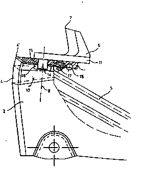
Figures 2 and 3 provide an enlarged view of one of the buckets 2 from the side
(Figure 2) and from above (Figure 3). The cutting teeth 4 and the scarifier 6 can be
seen in the drawing. The gathering area for the cutting teeth 4 has an
extension 10 towards the rear of the bucket 5 and serves as a support for the
area 11 around the scarifier 6. As can be seen From Figure 3, the scarifier 6 ispositioned 13 eccentrically to the bucket 12 (longitudinal axis 12) on the rear of
PAT6069T3
. ~ ' ''
.
2~
- 5 -
the bucket 5. A hole 15 has been drilled in the area of the cutting teeth 4 which
extends into the inside of the bucket, and into which a fitted attachment 14 (boits,
shaft butts or the like) can be inserted so that ;t protrudes into the support area 11
of the scarifier. The attachment 14 is mounted to the inside of the bucket with a
disk 16 that is welded on so that movement in the direction of the axis of
rotation 8 is insignificant and whereby a pivoting movement can be produced
around the axis of rotation 8. The section of the scarifier 6 is thicker in the
attachment area 13, and it narrows towards the cutting edge 7; the cross-sectionof the scarifier 6 thus changes from an approxirnately right angle to an acute
angle. Because of the extent of freedom of movement, the corresponding
scarifier 6 is able to adjust automatically, to any circumferential and swivel speed,
thereby achieving optimum tooth position with respect to the material to be
chipped off. Because of its special eccentric position in relation to the longitudinal
axis 12 on the rear of the bucket 5, each scarifier 6 cuts into the next depth of
cut, thereby making it easier for the cutting teeth 4 to loosen the previously
started layer and load the buckets 2. The attaching elements 17 for the series of
teeth 18 (only outlined here) making up the rear of the buckets 5 are fitted onto
the corresponding extension 10.
PAT6069T3
- ..-
.