Language selection

Search

Patent 2072437 Summary

Third-party information liability

Some of the information on this Web page has been provided by external sources. The Government of Canada is not responsible for the accuracy, reliability or currency of the information supplied by external sources. Users wishing to rely upon this information should consult directly with the source of the information. Content provided by external sources is not subject to official languages, privacy and accessibility requirements.

Claims and Abstract availability

Any discrepancies in the text and image of the Claims and Abstract are due to differing posting times. Text of the Claims and Abstract are posted:

  • At the time the application is open to public inspection;
  • At the time of issue of the patent (grant).
(12) Patent: (11) CA 2072437
(54) English Title: EFFICIENTLY PACKAGED HUMIDIFIER DEVICE
(54) French Title: HUMIDIFICATEUR
Status: Expired and beyond the Period of Reversal
Bibliographic Data
(51) International Patent Classification (IPC):
  • F24F 06/04 (2006.01)
(72) Inventors :
  • CHIU, BERNARD (United States of America)
  • WANG, JUI-SHANG (Taiwan, Province of China)
  • MARINO, FRANK (United States of America)
(73) Owners :
  • DURACRAFT CORPORATION
  • HONEYWELL CONSUMER PRODUCTS, INC.
(71) Applicants :
  • DURACRAFT CORPORATION (United States of America)
  • HONEYWELL CONSUMER PRODUCTS, INC. (United States of America)
(74) Agent: RICHES, MCKENZIE & HERBERT LLP
(74) Associate agent:
(45) Issued: 2001-12-04
(22) Filed Date: 1992-06-26
(41) Open to Public Inspection: 1993-01-09
Examination requested: 1999-03-29
Availability of licence: N/A
Dedicated to the Public: N/A
(25) Language of filing: English

Patent Cooperation Treaty (PCT): No

(30) Application Priority Data:
Application No. Country/Territory Date
07/726,677 (United States of America) 1991-07-08

Abstracts

English Abstract


A humidifier including a base defining a reservoir
adapted to retain a liquid volume; the base having an open top
and a horizontal cross section including a substantially rectangular
portion, and a substantially circular portion intersecting and
projecting into the rectangular portion; and the base including a
substantially circular sidewall forming the circular portion, a
substantially rectilinear endwall, a first substantially rectilinear
sidewall extending between the circular sidewall and one end of the
endwall, and a second substantially rectilinear sidewall extending
between the circular sidewall and an opposite end of the endwall;
the first sidewall, the second sidewall and the endwall forming
the rectangular portion. The humidifier also includes an inlet
wall defining an air inlet; a blower assembly demountably supported
by the base and covering the open top; the blower assembly comprising
an upper wall defining an air outlet disposed above the circular
portion, a fan blade disposed between the circular portion and
the air outlet, and an electrical motor coupled to the fan blade;
and a wick retained by the base in the rectangular portion and
comprising a source portion disposed in the reservoir and an
evaporative portion disposed thereabove and between the air inlet
and the fan blade, the wick adapted to provide liquid flow by
capillary action from the source portion to the evaporative
portion.


Claims

Note: Claims are shown in the official language in which they were submitted.

-9-
CLAIMS
1. A humidifier comprising:
a base defining a reservoir adapted to retain a
liquid volume; said base having an open top and a horizontal cross
section including a substantially rectangular portion, and a
substantially circular portion intersecting and projecting into
said rectangular portion; and said base comprising a substantially
circular sidewall forming said circular portion, a substantially
rectilinear endwall, a first substantially rectilinear sidewall
extending between said circular sidewall and one end of said endwall,
and a second substantially rectilinear sidewall extending between
said circular sidewall and an opposite end of said endwall; said
first sidewall, said second sidewall and said endwall forming said
rectangular portion;
an inlet wall defining an air inlet;
a blower assembly demountably supported by said base
and covering said open top; said blower assembly comprising an
upper wall defining an air outlet disposed above said circular
portion, a fan blade disposed between said circular portion and
said air outlet, and an electrical motor coupled to said fan
blade; and
wick means retained by said base in said rectangular
portion, said wick means comprising a source portion disposed in
said reservoir and an evaporative portion disposed thereabove and
between said air inlet and said fan blade, said wick means adapted
to provide liquid flow by capillary action from said source portion
to said evaporative portion.
2. A humidifier according to claim 1 wherein said
inlet wall is vertically aligned with and above said endwall.

-10-
3. A humidifier according to claim 2 wherein said
wick means is disposed adjacent to and substantially parallel to
said inlet wall and said endwall.
A humidifier according to claim 3 wherein said
wick means is substantially co-extensive with said inlet wall
and said endwall.
5. A humidifier according to claim 4 wherein said
endwall and said inlet wall are formed by a single common wall.
6. A humidifier according to claim 5 wherein said
air inlet extends between opposite vertical edges of said inlet wall.
7. A humidifier according to claim 5 including a
rotatable air deflector supported by said upper wall in said air
outlet.
8. A humidifier according to claim 5 including air filter
means disposed between said air inlet and said evaporative portion
of said wick means.
9. A humidifier according to claim 5 wherein said base
comprises stop means disposed centrally within said circular sidewall
and projecting upwardly to a desired maximum level of the liquid
volume.
10. A humidifier according to claim 5 wherein said
base defines recessed handle portions projecting into said reservoir
and positioned at a desired maximum level of the liquid volume.
11. A humidifier according to claim 5 wherein said
blower assembly includes electrical control means for activating
said electrical motor.

-11-
12. A humidifier according to claim 1 wherein said
air inlet extends between opposite vertical edges of said inlet wall.
13. A humidifier according to claim 1 including a
rotatable air deflector supported by said upper wall in said air
outlet.
14. A humidifier according to claim 1 including air
filter means disposed between said air inlet and said evaporative
portion of said wick means.
15. A humidifier according to claim 1 wherein said
base comprises stop means disposed centrally within said circular
sidewall and projecting upwardly to a desired maximum level of the
liquid volume.
16. A humidifier according to claim 1 wherein said
base defines recessed handle portions projecting into said reservoir
and positioned at a desired maximum level of the liquid volume.
17. A humidifier according to claim 1 wherein said
blower assembly includes electrical control means for activating
said electrical motor.
18. A humidifier apparatus comprising:
a unitary, integrally molded base defining stop means
and a reservoir adapted to retain liquid at a given maximum level,
said stop means projecting into a central portion of said reservoir;
a humidification unit removably mounted on said base
in a normal orientation above said reservoir and retaining
electrically energized humidifier means for producing dispersion
of liquid retained in said reservoir, said unit in the absence
of said stop means being shaped and arranged to permit re-
orientation into a position wherein portions of said electrically

-12-
energized humidifier means would be disposed in said reservoir
below said given maximum level, and wherein said stop means is
arranged to prevent said reorientation of said unit into any
positions wherein any portion of said electrically energized
humidifier means is below said given level.
19. A humidifier according to claim 18 wherein said
stop means is a hollow tube projecting up into said reservoir
from a bottom surface of said base means.

Description

Note: Descriptions are shown in the official language in which they were submitted.


_2_
This invention relates generally to a humidifier and,
more particularly, to a portable humidifier intended for domestic
and industrial use.
Various types of products are used to increase the
level of the humidity in an enclosed environment. With respect to
portable humidifying appliances, they may be broken dawn broadly
into two categories, one being the evaporation type and the other
being the steam vaporizer type. One well known type of evaporative
humidifier employs one wick element that produces by capillary
action liquid flow from a reservoir to a wick portion disposed in
a path of airflow produced by an electrical blower. Air moving
through the wick element evaporates its water content producing
vapor that is dispersed into the surrounding environment to increase
the humidification level thereof.
1~ Wick type humidifiers offer the advantages of low cost,
and relatively trouble free, clean operation. However, a need
exists for portable wick type humidifiers with increased output/
volume ratios, that is, the ratio of between the vapor output and
external dimensions of a particular humidifier unit.
The obaect of this invention, therefore, is to provide
an evaporative humidifier device exhibiting an improved, output/
volume ratio.
The invention is a humidifier including a base defining
a reservoir adapted to retain a liquid volume; the base having an
25 open top and a horizontal cross section including a substantially
rectangular portion, and a substantially circular portion intersecting

-3-
and projecting into the rectangular portion; and the base including
a substantially circular sidewall forming the circular portion,
a substantially rectilinear endwall, a first substantially
rectilinear sidewall extending between the circular sidewall and
one end of the endwall, and a second substantially rectilinear
sidewall extending between the circular sidewall arid an opposite
end of the endwall; the first sidewall, the second sidewall and the
endwall forming the rectangular portion. The humidifier also
includes an inlet wall defining an air inlet; a blower assembly
demountably supported by the base and covering the open top; the
blower assembly comprising an upper wall defining an air outlet
disposed above the circular portion, a fan blade disposed between
the circular portion and the air outlet, and an electrical motor
coupled to the fan blade; and a wick retained by the base in the
rectangular portion and comprising a source portion disposed in the
reservoir and an evaporative portion disposed thereabove and between
the air inlet and the fan blade, the wick adapted to provide liquid
flow by capillary action from the source portion to the evaporative
portion. The circular and rectangular portions optimize the output/
volume of the humidifier.
According to specific features of the invention, the
inlet wall is vertically aligned with and above the endwall; and
the wick is disposed adjacent to and substantially parallel to the
inlet wall and the endwall, and is substantially coextensive therewith.
These features further enhance the output/volume ratio of the
humidifier.

-4-
according to other features of the invention, the
endwall and inlet wall are formed by a single common wall, and
the air inlet extends between opposite vertical edges of the inlet
wall. These features simplify fabrication of the humidifier and
maximize air input.
According to another feature, the invention includes
a rotatable air deflector supported by the upper wall in the air
outlet. The rotatable air deflector facilitates selective control
of the humidifiers air discharge pattern.
According to yet another feature, the humidifier includes
a filter disposed between the air inlet and the evaporative portion
of the wick. The filter prevents clogging of the wick element.
According to a further feature of the invention, the
base comprises a stop disposed centrally within the circular sidewall
and projecting upwardly to a desired maximum level of the liquid
volume. The stop prevents inadvertent submersion of the blower
assembly in the liquid volume.
According to additional features of the invention, the
base defines handle portions projecting into the reservoir and
positioned at a desired maximum level of the liquid volume. The
handle portions serve the dual functions of handles for transporting
the humidifier and indicators for a desired liquid fill level.
These and other objects and features of the invention
will become more apparent upon a perusal of the following description
taken in conjunction with the accompanying drawings wherein:
Fig. 1 is a perspective view of the humidifier according
to the invention;
Fig. 2 is a top view of the humidifier shown in Fig. l;

_5_
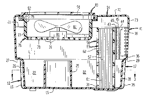
Fig. 3 is a cross sectional view taken along lines
3-3 of Fig. 4;
Fig. 4 is a cross sectional view taken along lines 4-4
of Fig. 2; and
Fig. 5 is a cross sectional view taken along lines
5-5 of Fig. 2.
An evaporative humidifier 11 includes a housing 12
including a base 13 and a lower assembly cover 14. Forming the
base 13 is a bottom wall 15, a circular sidewall 16, a common wall 17,
a first sidewall 18 extending between one end of the common wall 17
and the circular sidewall 16 and a second sidewall 19 extending
between an opposite side of. the common wall 17 and the circular
sidewall 16. The base 13 has an open top 21 and a lower internal
portion thereof defines a reservoir 22 adapted to retain a liquid
volume to a maximum level L. Projecting upwardly from the bottom
wall 15 centrally within the circular sidewall 16 is a cylindrical
stop 25 that terminates at the level L.
A recess 26 in a lower middle portion of the circular
sidewall 16 defines a downwardly projecting handle surface 27
aligned with the level L. Formed in the common wall 17 opposite to
the recess 26 is another recess 28 defining a downwardly projecting
handle surface 29 also aligned with the liquid level L. A cartridge
well 31 is formed in the bottom wall 7.5 and extends between the
first and second sidewalls 18, 19. Forming the common wall 17 is a
lower endwall portion 35 thereof and a vertically aligned upper
inlet wall portion 36. A plurality of spaced apart ribs 39 extending
between opposite edges of the inlet wall portion 36 define an air
inlet 41. Projecting inwardly from an upper portion of the first
sidewall 18 and adjacent to the inlet 41 are a pair of parallel,

_.. 2~~~~~'~
-6-
vertically oriented ridges 43, 44 that define a slot 45. A similar
slot (not shown) is formed in the sidewall 19.
As shown in Fig. 3, the base 13 has a cross section
that includes a circular portion 51 formed by the circular sidewall 16,
and a rectangular portion 52 formed by the endwall 35, the first
sidewall 18 and the second sidewall 19. The circular portion 51
intersects and projects into the rectangular portion 52 as shown
by a phantom, dashed line 53. Preferably, the base 13 is an
integrally molded unit.
ld Retained by the base 13 within the well 31 is a
cartridge 55 including a frame 56 and a plurality of wick elements
57 retained thereby. The wick elements 57 have lower source portions
61 disposed in the reservoir 22 and upper evaporative portions 62
disposed above the reservoir 22 adjacent to the air inlet 41 in the
inlet wall 36. Forming the wick element 57 is a conventional
absorbent material that produces by capillary action a flow of liquid
from the source portions 61 submerged in the water liquid volume
within the reservoir 22 upwardly to the evaporative portions 62.
An air filter 65 is retained between the slot 45 on the first
sidewall 18 and a similar slot (not shown) on the second sidewall 19
and separates the evaporative portions 62 of the wick elements 57
from the air inlet 41.
The blower assembly 14 includes a cover 71 having an
upper horizontal wall 72 and a skirt portion 73 projecting downwardly
therefrom. The skirt portion 73 engages and conforms to the open
top edge 21 of the base 13. Formed in the upper wall 72 is a
circular air outlet opening 75. A blower enclosure 76 includes a
cylindrical sidewall 77 projecting downwardly from the outlet
opening 75 and a bottom wall 78 defining air passages 79. Preferably,

~~'~2~~~°~
-7_.
the upper wall 72, the skirt portion 73 and the blower enclosure 76
are an integrally molded unit.
Also included in the blower assembly 14 are an electrical
motor 81, a fan blade 82, a circular deflector plate 83 and
electrical controls 84 including an electrical switch 85. The fan
blade 82 is rotatably coupled to the motor 81 which is retained
within the blower enclosure 76. As shown in Figs. 2 and 4, the
fan blade 82 and the air outlet 75 are positioned directly above
the circular portion 51 of the base 13 and are arranged con-
centrically therewith. The circular deflector plate 83 including
inclined deflector vanes 91 is rotatably mounted on a circular
shoulder portion 92 connecting the upper wall 72 to the cylindrical
sidewall 77 of the blower enclosure 76.
Prior to use of the humidifier 11, the blower assembly
14 is removed from the base 13 and the reservoir 22 is filled to
the level L with a suitable liquid such as water. The recessed
handle surfaces 27, 29 function as visible indicators of the
desired maximum liquid level. After filling of the reservoir 22,
the blower assembly 14 is replaced on the base 13 and the humidifier
device 11 is positioned in an area in which humidification is
desired.
Actuation of the electrical switch 85 energizes the
electrical motor 81 to produce rotation of the fan blade 82. The
rotating fan blade 82 draws air in through the air inlet 41 for
discharge through the deflector plate 83. Included in the air flow
path between the inlet 41 and the outlet 75 are the air filter 65,
the evaporative portion 62 of the wick elements 57 and the passages
79 in the bottom wall 78 of the blower enclosure 76. Air passing

~~~~~~e)~
_g_
through the evaporative portions 62 produces evaporation of its
liquid content and the resultant vapor is entrained in the air
flow for discharge into the surrounding environment through the
air outlet 75. Selection of a desired discharge pattern is
obtained by appropriate rotation of the deflector plate 83 on the
shoulder portion 92 of the blower enclosure 76. The filter 65
removes dust particles in the air flowing between the inlet 41
and the wick cartridge 55 to thereby prevent clogging 'that would
reduce the efficiency of the evaporative portions 62 of the wick
elements 57.
Obviously, many modifications and variations of the
present invention are possible in light of the above teachings.
Tt is to be understood, therefore, that the invention can be
practiced otherwise than as specifically described.

Representative Drawing
A single figure which represents the drawing illustrating the invention.
Administrative Status

2024-08-01:As part of the Next Generation Patents (NGP) transition, the Canadian Patents Database (CPD) now contains a more detailed Event History, which replicates the Event Log of our new back-office solution.

Please note that "Inactive:" events refers to events no longer in use in our new back-office solution.

For a clearer understanding of the status of the application/patent presented on this page, the site Disclaimer , as well as the definitions for Patent , Event History , Maintenance Fee  and Payment History  should be consulted.

Event History

Description Date
Time Limit for Reversal Expired 2004-06-28
Letter Sent 2003-06-26
Grant by Issuance 2001-12-04
Inactive: Cover page published 2001-12-03
Inactive: Final fee received 2001-08-24
Pre-grant 2001-08-24
Notice of Allowance is Issued 2001-06-18
Letter Sent 2001-06-18
Inactive: Approved for allowance (AFA) 2001-06-06
Inactive: Application prosecuted on TS as of Log entry date 1999-04-09
Inactive: Status info is complete as of Log entry date 1999-04-09
Letter Sent 1999-04-09
Request for Examination Requirements Determined Compliant 1999-03-29
All Requirements for Examination Determined Compliant 1999-03-29
Letter Sent 1998-02-02
Inactive: Multiple transfers 1997-11-19
Application Published (Open to Public Inspection) 1993-01-09

Abandonment History

There is no abandonment history.

Maintenance Fee

The last payment was received on 2001-03-23

Note : If the full payment has not been received on or before the date indicated, a further fee may be required which may be one of the following

  • the reinstatement fee;
  • the late payment fee; or
  • additional fee to reverse deemed expiry.

Patent fees are adjusted on the 1st of January every year. The amounts above are the current amounts if received by December 31 of the current year.
Please refer to the CIPO Patent Fees web page to see all current fee amounts.

Fee History

Fee Type Anniversary Year Due Date Paid Date
MF (application, 5th anniv.) - standard 05 1997-06-26 1997-05-27
Registration of a document 1997-11-19
MF (application, 6th anniv.) - standard 06 1998-06-26 1998-05-22
Request for examination - standard 1999-03-29
MF (application, 7th anniv.) - standard 07 1999-06-28 1999-05-06
MF (application, 8th anniv.) - standard 08 2000-06-26 2000-03-21
MF (application, 9th anniv.) - standard 09 2001-06-26 2001-03-23
Final fee - standard 2001-08-24
MF (patent, 10th anniv.) - standard 2002-06-26 2002-05-02
Owners on Record

Note: Records showing the ownership history in alphabetical order.

Current Owners on Record
DURACRAFT CORPORATION
HONEYWELL CONSUMER PRODUCTS, INC.
Past Owners on Record
BERNARD CHIU
FRANK MARINO
JUI-SHANG WANG
Past Owners that do not appear in the "Owners on Record" listing will appear in other documentation within the application.
Documents

To view selected files, please enter reCAPTCHA code :


To view images, click a link in the Document Description column (Temporarily unavailable). To download the documents, select one or more checkboxes in the first column and then click the "Download Selected in PDF format (Zip Archive)" or the "Download Selected as Single PDF" button.

List of published and non-published patent-specific documents on the CPD .

If you have any difficulty accessing content, you can call the Client Service Centre at 1-866-997-1936 or send them an e-mail at CIPO Client Service Centre.

({010=All Documents, 020=As Filed, 030=As Open to Public Inspection, 040=At Issuance, 050=Examination, 060=Incoming Correspondence, 070=Miscellaneous, 080=Outgoing Correspondence, 090=Payment})


Document
Description 
Date
(yyyy-mm-dd) 
Number of pages   Size of Image (KB) 
Drawings 1993-12-12 3 137
Abstract 1993-12-12 1 32
Claims 1993-12-12 4 108
Description 1993-12-12 7 230
Representative drawing 2001-10-30 1 26
Representative drawing 1999-06-15 1 46
Reminder - Request for Examination 1999-02-28 1 117
Acknowledgement of Request for Examination 1999-04-08 1 178
Commissioner's Notice - Application Found Allowable 2001-06-17 1 165
Maintenance Fee Notice 2003-07-23 1 174
Correspondence 2001-08-23 1 35
Fees 2001-03-22 1 39
Fees 1997-05-26 1 42
Fees 1998-05-21 1 42
Fees 1999-05-05 1 38
Fees 2000-03-20 1 37
Fees 1996-06-03 1 46
Fees 1995-05-29 1 53
Fees 1994-03-21 1 35