Note: Descriptions are shown in the official language in which they were submitted.
~72~2
IMP~OV~D CE~CK VALVK
FI~LD OF TEE I~VZRTIO~
This lnvention relates to a~ improved check valve which
allows passage of a fluid or gas in one direction only. This check
valve is particularly useful in fluid- or gas-asslsted injection molding
wherein the check valve allows fluid or ga3 to be injected into a molten
plastic flow path while preventing or mlnlmi~lng the back flow of molten
plastic into the fluid or gas supply system or lines.
BAC~G~OU~D OF Ta~ I~VE~TIOR
In gas-asslsted injection molding, a pres~urized gas is
injected into a molten thermoplastic stream. One of the problems
associated with such a system i9 back flow of the molten thermoplastic
into the pressurized gas ~upply lines. The thermoplaseic can harden in
the pressurized gas supply lines thereby restricting gas flow and,
ultlmately, blocking gas rlow. Several methods or approaches have been
advanced to overcome thls problem.
For esa~ple, in U.S. Paeent ~o. 4,905,901, a complicated
baffle deslgn was incorporated into the gas flow path to retard the flow
of plastic into the gas flow path. The baffle wa~ intended to provide a
small diameter, tortuous passage through which the gas could easily flow
but through which the viscou3 molten thermoplastic could flow only with
8reat dlfflculty. And in U.S. Patent Ro. 4,855,094, an attempt was made
to solve this same problem by providing gas passage3 of sufficiently
small diameter to ~esist entry of the molten thermoplastic. Gas
passages of 0.005 to 0.040 inches were sAid to be effective to
pre~enting entry of the molten thermopla~tic material. Both of these
approaches have been less quccessful than de~ired. Although such
approaches may> in fact, re~trict the entry of the thermoplastic into
the g~s passageways, they do not prevent such entry. Over time, the gas
passages still become re-qtricted and, ultimately, blocked. In some
instances, it i9 nece~ary to clean out ~he gas passages every few hours.
Check valves with ball-shaped valve member~ have also been
used in gas-assisted injection molding applications. For example, in
U.S. Patent No. 4,g42,006, a ball check valve i9 provided in an
injection nozzle. The actual valve is located within the gas
passageway. When the valve is in the closed position7 molten plastic
enterlng the gas passageway can contact and coat at least a portion of
the ball member. As the ball valve repeatedly move~ from its open to
closed positions, the ball may rotate. Portions of the ball which have
contacted plastic material ln earlier cycles may, in later cycles, act
a~ the sealing surface. In such cases, plastlc material on the sealing
surface~ will prevene the valve from seallng. This failure to seal will
allow even more plastic material to enter the gas pa3sageway and contact
the ball in later in~ectlon cycles, thus accelerating the problem. Ball
valves of the type used in the prLor art have, therefore, a limlted
useful lifetime and require frequent cleaning. In some lnstances, it
may be neces~ary to clean ~uch check valve~ every few operational
hours. Such cleaning requires dismantling of the nozzle ltself, which,
depsnding on the nozzle design, can be very involved and time consuming.
It is, therefore, desirable to provide a method by which
plastic material can be prevented, or at least minimized, from entering
ga~ pas~ageways in gas-As~i~ted in~ection molding. The check valves of
the present invention provide signiflcantly improved performsnce over
the methods currently in use to prevent plAstic material from entering
and clogging ga~ pas~ageways ln a gas-assisted in~ection moldln~
apparatus. This improvement Ls accompllshed by providin4 a check valve
2~72a~2
wherein the sealing surfaces are not in dlrect contact with the plastic
material. When cleaning i5 necessary, the check valves of the present
invention can be di3assembled and cleaned quite easily. These check
valves can also be used in other application3 and environments.
S~MMU~7 OF T~ VERTIOR
In accordance with this invention, an improved check valve
i9 provided. This check valve i9 particularly useful and adapted for
fluid- or gas-assisted in~ection molding wherein the check valve allows
fluid or gas to b2 inJected into a molten plastic flow path while
preventing or minimizin~ the back flow of molten plastic Into the fluid
supply 3ystem or lines. The design of the check valve of the present
invention allows for a large sealing surface area. And, when used in an
injection molding machine, the contact of the molten plastic with the
sealing surfaces i9 prevented or, at least, minimized. Therefore, by
prevPnting or minimi7in8 such contact, the checX valves of the present
invention are less likely, as compared to prior art check valveq, to
fail to seal due to plastic adhering to the sealing surfaces.
One ob~ect of the present inventlon is to provide a checX
valve adapeed for pas~age of a fluid from an upstream to a downstream
direction, said check valve comprisin8
(a) a valve body with an upstream end in fluid communication with
a fluid supply line and a downstream end in fluid communication with a
fluid deliveFy line, the valve body lncluding
(1) a bore extending through the valve body ln fluid
communication with the upstream end and the downstream end,
and
2~72~
(2) a valve chamber provided in the bore and i~ fluid
communication with the bore wherein the valve chamber is
tapered such that the small diameter of the valve chamber is
adjacent to the upstream end of the valve body, the large
diameter of the valve chamber is ad~acent to the downstream
end of the bore, and the large diameter of the valve chamber
is larger than the bore diameter; and
(b) a tapered valve member adapted to fit within the valve chamber
and movable therein between a closed poqition and an open position,
wherein
(1) when the tapered valve member is in the closed
position, the tapered surfaces of the valve member are
sufficiently engaged with the tapered surface~ of the valve
chamber to prevent fluid from passing from the downstream
end to the upstream end of the bore, and
(2) when the tapered valve member i3 in the opened
position, the tapered surfac2s of ehe valve member are
displaced fro~ the tapered Aurfaces of ths valve chamber
whereby fluid can pass from the upstream end to the
downstream end of the bore.
A~other ob~ect of the present invention is to provide a
nozzle for use in a fluid-assisted pla tic in~ection molding apparatus,
said nozzle incIudlng
(a) a nozzle body having an upstream end for fluid communication
with an end of an associated plastic in~ection molding machine and a
downstream end for fluid communication with a sprue of an associated
mold body, sald nozzle body lncluding
(1) an axially extending bore for establlshing a
pla~tic flow path,
.
~72~2
(2) a second bor~ extending through, and non-axiallY
to, the nozzle body where the first end o~ ~he second bore
is in fluid co~munication with a fluid supply and the second
end of the second bore i9 in fluid communication with, and
intersects, the axially extending bore, and
(3) a vaive chamber provlded in the second bore and in
fluid communica~ion ~ith the second bore wherein the valve
chamber i9 tapered such that the small diameter of the valve
chamber is adjacent to the first end of the second bore, the
large diameter of the valve chamber i9 ad~acent to the
second end of the second bore, and the large diameter of the
valve chamber i9 larger than the second bore diameter; and
(b) a tapered valve member adapted to fit within the valve chamber
and movable therein between a closed position and an open position,
wherein
(1) when the tapered vslve member i9 in the closed
position, the tapered surfaces of ths valve member are
sufficlently engaged ~ith the tapered 3urfaceR of the valve
chamber to prevent fluid from paQsiD~ from the second end of
the second bore to the firs~ end of thP second bore, and
(2~ when the tapered valve member i~ in the opened
position, the tapered ~urfaces o~ the valve member are
displaced from the tapered surfaces of the valve chamber
whereby fluid can pass from the first end of the second bore
to the second end of the second bore.
Another ob~ect is to provide a sub~tantially dlsk-~haped
body adapted for insertion between a molten thermoplastic ln~ection
nozzle and a mold body in a fluid-a9sisted pla9tic in~ection molding
apparatus, sAid disk-shayed body including
2~72~2
(a) a thermoplastic passageway extending through the disk-shaped
body wherein the thermoplastlc passageway has an upstream end for
communication with the end of the in~ection moldin~ nozzle and a
downstream end for fluid communication with a sprue of the mold body;
~ b) a second passageway e~tendlng through the disk-shzped body
where ~he first end of the second passageway is in fluid communication
with a fluid supply and the second end of the second passageway is in
fluid communication with, and intersects, the thermoplastic passageway,
and
(c) a valve chamber provided in the second passageway and in fluid
communication with the second passageway wherein ehe valve chamber is
tapered such that the small diameter of the valve chamber is adJacent to
the first end of the second passageway, the large diameter of the valve
chamber is ad~acent to the second end of the lecond pa3sageway, and the
large diameter of the valve chamber i9 larger than the second pas~aeeway
diameter; and
(d) a tapered valve member adapted to fit within the valve chamber
and movable therein between a closed position and an open position,
wherein
~ 1) when the tapered valve member is in the closed
positlon, ehe tapered surfaces of the valve member are
sufficlently engaged with the tapered qurfaces of the valve
chamber to prevent fluid from passing from the second end of
the second passageway to the first end of the second
passageway, and
(2) when the tapered valve member is in the opened
position, the tapered surfaces of the valve member are
displaced from the tapered surfaces of the valve chamber
whereby fluid can pass from the first end of the second
passageway to the second end of the second passageway.
2~7~
Still another obJect of the present invention is to provide
an apparatus for molding a plastlc part, aaid apparatus lncludlng
(a) a source of molten thermoplastic material;
(b) a source of in~ection fluid;
(c) a mold body for receiving the molten thermoplastic material
from the molten thermoplastlc material source, where the mold body
contains a sprue;
(d) an injection nozzle secured between the source of
thermoplastic material and the mold body, where the in~ectlon nozzle
includes
(1) a nozzle body having an upstream end for fluid
communication with the source of thermoplastic material and
a downstream end for fluid communication with the sprue of
the mold body, said nozzle body including
(A) an axially extending bore for establlshing a
thermoplastic flow path,
(B) a .~econd bore extending through, and
- non-axially to, the nozzle body where ehe first end of
the second bore is in fluid communication with a fluid
3upply and the ~econd end of the second bore i3 in
fluid communication wlth, and inter~ects, the axially
extend~n~ bore, and
(C) ~ valve chamber provided in the second bore
and in fluid communicatlon with the second bore
wherein the valve chamber iq tapered such that the
small diameter of the valve chamber i9 ad~acent to the
first end of the second bore, the large diameter of
the valve chamber is ad~acent to the second end of the
second bore, and the large diameter of the valve
chamber is larger than the second bore diameter; and
.
` ` ' '
. .
.:. .
(2) a tapered valve member adapted to fit withln the
valve chamber and movable therein between a closed position
and an open position, wherein
(A) when the tapered valve ~ember is in ~he
closed position, the tapered surfaces of the val~e
member are sufficiently engaged with the tapered
surfaces of the valve chamber to prevent fluid from
passing from the second end of the second bore to the
first end of the second bore, and
(B) when the tapered valve member is in the
opened position, the tapered surfaces of the valve
member are displaced from the tapered surfaces of the
valve chamber whereby fluld can pasq from the first
end of the second bore to the second end of the second
bore.
And ~till another ob~ect is to provide an apparaeus for
molding a plastic part, said apparatus including
(a) a source of ~olten thermoplastic material;
(b) a source of in~ection fluid;
(c) a mold body for receiving the molten thermoplastic material
from the molten thermopla~tic material source, where the mold body
contains a sprue;
~ d) an ln~ectlon nozzle in fluid communication with the
thermoplastic material source; and
(e) a substantially disk-shaped body secured between, and in fluid
~ communlcation with, the in~ection nozzle and the sprue, where the
disk-shaped body includeR
. . j , . .
2~72~2
:`
- (1) a thermoplastic passageway extending through the
disk-shaped body wherein the thermoplastic passageway has an
upstream end for communication with the end of the injection
noz~le and a downstream end for fluid communication with the sprue
of the mold body;
(2) a second passageway extending through the disk-shaped
body where the first end of the second passageway is in fluid
communication with the fluid source and the second end of the
second passageway is in fluld communication with, and intersects,
the thermoplastic pasqageway, and
(3) a valve chamber provided in the second passageway and in
fluid communication with the second passageway wherein the valve
chamber is tapered such that the small diameter of the valve
chamber is ad~acent to the first end of the second passageway, ~he
large diameter of the valve chambes is ad~acent to the second end
of the second pa~sageway, and the large diameter of the valve
chamber is larger than the second passageway diameter; and
(4) a tapered valve member adapted to fit within the valYe
chamber and movable therein between a closed position and an open
position, wherein
(A) when the tapered valve member iY in the closed
position, the tapered surfaces of the valve member are
sufficiently engaged with the eapered surfaces of the valve
chamber to prevent fluid from passing from the second end of
the second passageway to the first end of the second
passageway, and
(B) when the tapered valve member i9 in the opened
position, the tapered surfaceq of the valve member are
displaced from the tapered surfaces of ehe valve chamber
- whereby fluid can pass from the first end of the second
pas~agey~y to ehe second end o~ the second pas~ageyay.
. 9
.
,
2~7~4~2
These and other objects and advantages of the present
invention will become apparent through the following description of the
preferred embodiments of the invention and with reference to the
drawings provlded.
8~I~F DESC~IPTIO~ OF T~ DRAWI~GS
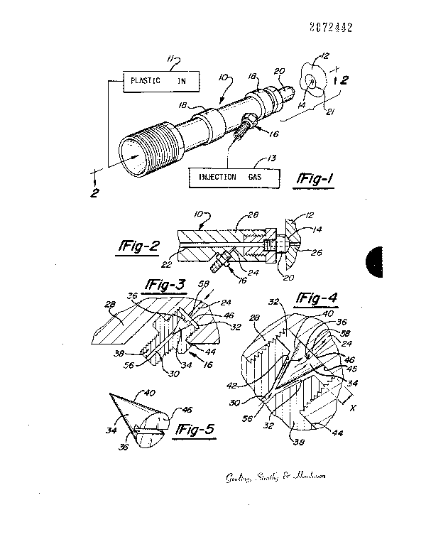
Figure 1 i9 a perspective view of an in~ection nozzle
equipped with the check valve of the present invention.
Figure 2 i9 a partial sectional view of the in~ec~ion nozzle
of Figure 1 taken along section line 2-2.
Figure 3 i~ an enlarged sectional view of the check valve of
Figure 2. Thi~ figure show3 the check valve in the closed position
wherein gas or plastic bacX flow in the direction of the arrow is
prevented.
Figure 4 ls an another enlarged sectional view of the check
valve of Figure 2. This figure show~ the check valve in the open
poqition wherein gas or fluid is allowed to flow past the valve member
and into the plastic flow path.
Figure 5 is a perspective view of the valve member of the
check valve showing a slot for gas passage on ~he base surface of the
valve member.
Figure 6 is another enlarged section vtew of the chec~ valve
of the present invention wherein the slot for gas pas3age i located in
the noz71e body. The check valve is shown in the open posltlon.
-- 2~72~
Figure 7 i9 a partial sectional view of the check valve of
Figure 6 taken along section line 7-7.
Figure 8 is an exploded, perspective view of a disk
containing the check valve of the present invention. The disk is
designed to be placed between an injection molding machine nozzle and a
mold body Ln an injection molding apparatus.
The present invention is not to be limited to the details of
construction and arrangement of parts as illustrated in the accompanying
drawings as the inveneion is capable of other embodiments and of being
practiced in various ways within the ~cope of the appended claims.
Furthermore, the terminology used in thi~ present specification is for
the purpose of de~cription and nos of llmitation.
D~SC~TPTIO~ OF TH~ P~EF~B~D ~MBODIME~TS
The present invention generally relates to check valves
wherein flow of a fluld or gas i9 allowed in one direction but is
prevented in the reverse direction. The check valves of the present
invention can generally be used ln fluid or gas lines in a wide array of
equipment and environments. The present check valves are, however,
especially designed and adapted for use in fluid-assiqted or
gas-a~sisted in~ection molding methods and apparatus. In such injection
molding applications, fluid or gas injection can be through an injection
nozzle, through the sprue bushing, through the runner, or directly into
the article cavity using the check valve of the present invention.
2~72fl~2
The check valves of the present invention provlde a large
surface area for sealing. And contact of the actual sealing area or
surfaces of the check valve with ~aterial attempting to flow backwards
through the check valve (i.e., flow in the direction not allowed) is
prevented or, at least, minimized. ~his feature i9 especially important
in injection molding operations wherein a fluid or gas is injected into
a molten thermoplastic flow path. In such an environment, the molten
plastic has a tendency to flow down the fluid or gas injection lines
once the fluid or gas flow has been terminated. Molten plastic reaching
the seallng surfaces may coat or solidify on the sealing surfaces and
prevent sealing during later ln~ection cycles. Such a failure to seal
defeats the purpose of the check valve. The check valYe~ of the present
invention, by preventing or at least minimizing contact of molten
plastic with the sealing surfaces, overcomes this problem of the prior
art. Thus, the check valves of the present invention should have a
~ignificantly longer useful lifetime between cleanings to remove plastic
material from the sealing surface than the check valves currently in
use.
.
The check valves of the present invention have essentially
one moving part and are essentially self-actuating. In addition, the
check valves of the present invention are designed to be removed and
dlsassembled easily for cleaning if they are eventually rendered
inoperative due to plastic contacting and adhering to the sealing
surfaces. Those skilled in ~he art will recognize other advantages of
the check valve~ of the present invention from the detailed description
included herein. Although the following description generally describes
the inventive check valves in the environment of an injection molding
apparatus, it should be recognized that these check valves can be used
in many other systems and apparatus to directionally control the flow of
12
.
2~2~2
a fluid or gas. For purposes of this specification, the terms "fluid"
and "gas'' are used interchangeably and the use of one should be
considered to include the other.
Figure 1 shows an injection nozzle 10 for the injection of
molten thermoplastic from a source of molten plastic or thermoplastic
resin 11 into a mold body 12 and a mold cavity or cavities (not shown)
contained within the mold body 12. The nozzle 10, and more specifically
the nozzle tip 20, mate with the nozzle mating surface 21 of the mold
body 12 such that plastic i9 injected into the mold cavity or cavi~ies
(not shown) via sprue 14. A gas is injected into the molten plastic
material from a gas source 13 via the chec~ valve assembly 16. Band
heaters 18 assist in keeping the plastic maserlal in a molten state as
it passes through the nozzle.
The provisions for the in~ection of the molten plastic
material and the gas within the injection nozzle 10 i5 shown more
clearly in Figure 2. Molten plastic flows down the ylastic flow path 22
towards the nozzle tip 20 and mold body 12. Once plastic reache~ the
mold body 12, the plastic flows through the sprue 14 and down the sprue
flow path 26 to the mold cavity or cavities (not shown). Intersecting
the plastic flow path within the nozzle body 28 is the gas flow path 24
through which gas can ~e injected in~o the molten plastic. The gas flow
path 24 should generally form an acute angle with the plastlc flow path
22. This angle i9 approximately 45~ in Figure 2. With such an acute
angle, the Bas injected into the plastic flow path 22 is flowlng in the
~ame general direction as the plastic, thereby minimizing turbulence in
the plastic stream. Generally, this angle ls preferably in the range of
about 30 to 60, with an angle of about 4S being most preferred. The
diameter of the ga~ flow path 24 should generally be ln the range o~
about 0.01 to 0.10 inches in dia~eter and preferably in the range of
13
.' "
72~
0.03 to 0.06 inches in dlameter. Flow paths of larger dimensions can be
used, however, if desired (especially for applications other than
gas-assisted in~ection moldlng). Flow paths or passageways of less than
0.1 inch diameter will, however, at least retard ~he en~ry of molten
plastic into the gas flow path 24 and valve chamber 32.
Referring now to Figures 3 and 4, the operation of the check
valve of this invention will be explained. Figure 3 shows the check
valve in the closed position, whereby gas or molten plastic cannot flow
in the direction of the arrow. The check valve assembly 16 is
threadable engaged in the nozzle body 28 such that ga3 flow path 24 and
the valve chamber 32 are in fluid communication. As is shown more
clearly in Figure 4, valve chamber 32 includes an upper portion and a
tapered portion designed to receive the tapered valve member 34.
Chamber 32 is defined and formed by fltting valve body 38 into nozzle
body 28 as shown in Flgures 3 and 4. In the closed position, tapered
valve member 34 i9 ~eated in the tapered portion of valYe chamber 32
such that gas flow path 24 is not in fluld communication with the gas
supply passageway 30. In other words, when in the closed poAition, gas
cannot flow through gas supply passageway 30, around tapered valve
member 34 into the valve chamber 32, and into gas flow pa~h 24. Such a
flow i9 prevented by the close mating of the sealing surfaces 40 of the
tapered valve member 34 with the sealing surfaces 42 of the tapered
portlon of the valve chamber 32. The seallng surface~ 40 and 42 are
best shown in Figure 4. The sealing force i9 provided by pressure from
the plastic flow path 22 acting upon the face 40 of the tapered valve
member 34 thereby forcing the valve member 34 into the tapered portion
of the valve chamber 32.
14
2 a ~ 2
-
Figure 4 shows the check valve in the open position, wnereby
gas can flow from the upstream end 56 to the downgtream end 58 of the
check valve assembly 16. The gas flows from the source of gas 13 (sho-~n
in Figure 1) through gas supply passageway 30, through valve chamber 32
and around valve member 34, through slot 36, and shrough gas flow path
24. From gas flow path 24 the 8as enters pla~tic flow path 22 as shown
in Figure 2.
As illustrated in Figures 3 and 4, the check valve of this
present invention has one moving part, namely valve member 34 which
moves from it~ sealed or closed position shown in Figure 3 to its open
position shown in Figure 4. The check valve is essentially
self-actuating. Gas pressure applied to the upstream end 56, if
sufficient to overcome any back pressure exerted form the downstream end
58, forces the valve member 34 out of the tapered portion of the valve
chamber 32, thereby breaking the seal between the sealing surfaces 40 of
the valve member 34 and the sealing surfaces 42 of the valve chamber
32. The gas pressure applied to the upstream end 58 forces the face 46
against the nozzle side 45 of the valve chamber 32. Valve member 34, in
moving from its closed to open position, moves a distance of "x" as
shown in Figure 4; this diqtance is simply the depth of the non-tapered
portion of valve chamber 32. Normally, thls depth "x" will be in the
range of about 0.025 to 0.1 inches, although smaller or larger values
are acceptable (e~pecially in other applications). The depeh "x" can
easily be modified by simply increasing or reducing ehe length of the
portion of valve body 38 threaded into nozzle body 28 (i.e., that
portion of the valve body 38 from the end of the valve body containing
the tapered portion to shoulder 44).
;
2~2~2
The slot or groove 36 in the face 46 of the valve member,
which is clearly shown in Figure 5, is designed to allow gas to pass
from the valve chamber 32 into the gas flow path 24 in the nozzle body
28 when the valve member 34 is ln the open positlon. ~ithout t'nis slot
or equivalent gas passage, movement of the valve member 34 into its
position in Flgure 4 would force the face 46 of the valve member against
the nozzle body 28, thereby sealing off gas flow path 24 from the valve
chamber 32. If desired, more than one slot or groove 36 can be pro~ided
in face 46.
Alternative means can be provided to allow gas to pa3s from
the valve chamber 32 to the ga~ flow path 24 when the check valYe i9 in
the open position. For example, in Figures 6 and 7, a slot or groove 48
is provided in the nozzle body 28. ln this alternative embodiment, the
valve member 34 does not have a slot or groove in its large diameter
end. Slo~ 48 in the nozzle body in Flgures 6 and 7 performs the same
function and purpose as does slot 36 in valve member 34 in Figure 4. In
this alternative embodiment, when in the open po~ition, 8as flows from
the source of gas 13 (shown in Figure 1) through gas supply passageway
30, through valve chamber 32 and around valve member 34, through slot
48, and through gas flow path 24. From 3as flow path 24 the gas enters
plastic flow path 22 as shown in Flgure 2.
The valve member 34 has tapered sides 40 matched with the
tapered sides 42 of valve chamber 32. Valve member 34, a~ illustrated
in Figure ;, is in the form of a solid cone with the vertex (or smaller
diAmeter end) at the upstream end 56 of the check valve assembly 16 and
the circular end 46 (or larger diameter end~ at the downstream end 58 of
the check valve assembly 16. A truncated cone with the same general
shape would perform equally as well 90 long as there was sufflcien~
sealing surfaces 40. Other similar cone-liXe shapes fpr the valve
16
.
2 ~
member 34 would work if there was sufficient sealing surfaces and the
tapered portion of the valve chamber 32 was modified accordingly. For
example, the face 46 of the valve member could oval, triangular,
square, rectangular, or the like with the tapered portion of the valve
member 34 and the valve chamber 32 changed accordingly. Generally,
however, it is preferred that the valve member 34 be in the form of a
cone as illustrated in Figure S or in the form of a truncated cone (not
illustrated). With such cone-shaped and symmetrical (i.e., a circular
face 40) valve members, sealing is not affected if the valve member
should rotate about its ma~or axis in the valve chamber.
The materials of construceion for valve member 34 and valve
body 38 are not critical so long as they can withs~and the gas pressures
involved and do not exhibit excessive wearing due to repetitive opening
and closing. I~ is generally preferred, however, that when used in an
injection molding environment, the valve member 34 be made from hardened
stainless qteel. Although not wishing to limit the invention, Lt is
generally preferred that when used in an injection molding application
that the valve member 34 be in the range of about 0.1 to 0.2 inches in
diameter at the base with a diameter of about 1/8 inch being more
preferred. The an~le of the tapering per side of the valvs member 34
and the valve chamber 32 should be in the ranBe of 10~ to 25 with an
angle of about 15 beine preferred. If the tapering angle i9 too large,
there will be insufficient matin8 or sealing surfaces. And if the
tapering angle is too small, the valve may tend to freeze in the closed
position. With a base diameter of about 1/8 inch and a tapering angle
of about 15, the overall length of the valve member 34 illustra~ed in
Figure 5 would be about 1/2 inch. As one skilled in the art will
re~ogni~e, these dimen~ion3 can vary widely from those presented here,
especially for applications other then ga~- or fluid-assistsd in~ection
molding, without departing from the scope of the invention.
2~72~
-Figure 3 illustrates the use of the check valve of the
present invention in a disk-shaped body 50 designed to be inserted
between an injection molding nozzle of an injection molding machine (not
shown) and a mold body (not shown). Such a disk-shaped body i5 designed
to fit within the so-called sprue bushing (not shown) of a mold body.
The nozæle mating surface 21 is designed to mate with the nozzle tip
(not shown) of an associated thermoplastic injection nozzle (not
shown). Molten thermoplastic from such an associated injection nozzle
and machine passes lnto the disk-shaped body 50 via sprue 14 and then
through plastic flow path 52. From plastlc flow path 52 the molten
thermoplastic enters an associated mold body (not shown). Gas can be
in~ected into the plastic flow path 52 vla the gas ~low path 54. Such
gas enters the gas flow path 54 through check ralve assembly 16. The
check valve assembly 16 and its associated valve member 34 operate in
the same manner as described above. The valve assembly 1~ is shown
entering the slde of the disk-shaped body 50 in Figure 8. If desired,
the valve assembly could be moved to the circular face of the
disk-shaped body whlch contains sprue 14. In such a case, care should
be taken to assure that placement of the valve assembly does not
interfere with matlng between the dlsk-shaped body 50 and in~ection
nozzle. In Figure 8, 8as flow path 54 and plastic flow path 52 form an
acute angle. This angle (approximacely 60) is, however, some what
larger than the simllar angle defined in regard to Figure 2 above.
Nonetheless, 8as entering plastic flow path 52 from gas flow path 54
will be travellng in essentially the same direction as the plastic in
flow path 52.
```Injection nozzles 10 or dis~-shaped bodies 50 con~aining the check
valves of the present invention can be used in a conventional manner to
:-prepared molded plastic articles with gas-assisted in~ection molding
2~7~2
apparatus. In such a procedure, molten thermoplastic material is
injected into a mold CaYity~ followed by injection of a gas under
pressure. The gas forces the thermoplastic material throughout the mold
cavity to fill or pack out the extremities of the mold cavity while, at
the same time, forming gas channels wlthin the thermoplastic material.
The thermoplastic material is allowed to cool while maintaining the gas
pressure within the molded article. Once the molded article has cooled
sufficiently to be self supporting, the gas is vented and the article is
ejected using conventlonal methods. Preferably an inert gas, such as
nitrogen, carbon dioxide, argon, and the like is used. Nitrogen is
generally the most preferred pressurized gas.
19