Note: Descriptions are shown in the official language in which they were submitted.
CA 02072636 2002-06-14
1
ADDITION OF MAGNETIC MOIETIES IN FLUID BED HYDROCARBON
PROGRESSING
Backround of Invention
S ' In fluid bed particulate processing of hydrocarbon feedstocks, it is the
practice
to continuously add fresh particulate regularly, usually daily, and to
withdraw
equilibrium particulates prior to addition of fresh particulates. This
provides room for
the incoming fresh material.
Because of this procedure, which results in immediate complete mixing,
particulates both fresh in performance and low in contaminants (usually
nickel,
vanadium, iron, copper, and sodium) are unavoidably withdrawn together with
particulates which have been in the unit for varying times as long as two or
three
months or longer and have aged and drastically dropped in performance, while
simultaneously accumulating deleterious metal contaminant. The industry has
long
felt a need to have a means by which old catalyst can be selectively removed
without
entrainment of fresh catalyst.
Related Applications
The techniques of U.S. Ser. No. 07/332,079 filed Apr. 3, 1989 now U.S. Pat.
No. 5,147,527 are useful with the present invention.
Description Of The Prior Art
A manual search in the U.S. Patent Office, Class 55, subclass 3; Class
208, subclasses 52CT, 113, 119, 120, 121, 124, 137, 139, 140, 152, 2518,
and 253; Class 209, subclasses 8, 38, 39, and 40; and Class 502,
W091/1229t3 i~~~~fi..~, PGT/U591/004~a
subclasses 5, 20, 21, 38, 515, 516, and 518 found
principally the following references:
4
U.S. 4,359,379 and 4,482,450 to Ushio (assigned
Nippon Oil Company), both disclosed catalytic cracking
and hydrotreating processes for carbo-metallic
feedstocks by depositing (adding) nickel, vanadium, iron
9
and/or copper (originally contained in the heavy oil),
and then separating the old catalyst utilizing a high
11 gradient magnetic separator (HGMS). However the
12
13 magnetizement is derived from the metals contained in
1a the starting oil.
U.S. 2,348,418 (col. 2) to Roesch (Standard Oil,
1s
Indiana) regenerates catalyst by adding a magnetic
1$ substance, such as iron or nickel to the catalyst before
1s the catalyst is introduced into a magnetic separator.
21 U.S. 4,292,171 and 4,294,688 both to Mayer
22 (assigned Exxon) show catalytic reforming processes
23 which utilize the addition of magnetizable particles to
24 enhance catalyst separation via the use of magnetically
stabilized fluidized beds.
26
2~ U.S. 4,406,773 to Hettinger (assigned Ashland Oii)
28 discloses magnetic separation of high activity catalyst
29 from low activity catalyst.
31 U.S. 4,280,896 to Bearden passivates catalyst used
32 to crack hydrocarbon feedstocks wherein nickel, vanadium
33 and/or iron are deposited on the catalyst, but does not
3a mention use of magnetic separation.
3s However, none of the above patents deliberately
3~ adds magnetically active substances such as iron at a
3s constant rate over a period of time so that the
3s magnetically active substance builds up on the catalyst
4o in proportion to the age of the catalyst (the length of
WO 91/12298 ~r'~jf~~'~ PCT/US91/00484
3
time the catalyst has been in the hydrocarbon conversion
system). This addition of magnetic "hooks" which
4
facilitate separation of old (lower activity) from new
(recently added higher activity) catalyst is a novel
s feature of the present invention.
U.S. 4,541,920 to Seiver (Exxon) utilizes particles
s
containing a non-ferromagnetic component and a
ii catalytically active component composited with a
~2 ferromagnetic component so that the particles can be
lined up in a magnetic field.
14
Summary of the Invention
~s
If a harmless magnetic substance could be
continuously added to these particulates, so that it
accumulates at the same rate, as for example, nickel and
2o vanadium, it could be used to efficiently magnetically
2~ separate old particulates (those added to the system
22 sometime back) from new (those recently added to the
23 system, thus not heavily contaminated with metals, and
24 therefore valuable for recycle).
2s This invention teaches that intentional and
2~ continuous addition of iron can be used to facilitate
2$ separation of old catalyst from new.
29
3o Our work has shown that iron contamination of
3~ reduced crude cracking catalysts and even FCC catalysts
32 is a recurring catalytic cracking experience and this
33 contamination has enabled us to demonstrate that iron is
34 involved in effecting magnetic separation of used
catalysts. In fact, it appears to be the major element
3s affecting magnetic separation of old (metal
3~ contaminated) catalyst from new catalyst.
38
3s In the earlier years of fluid bed catalytic
4o cracking, iron was considered a mild poison, especially
WO 1 1 /122~,~7~ a ~ 4 PC1'/US9l /004q~
in the presence of high sulfur, and was rated equivalent
to 1/7 as deleterious as nickel. (Nickel Equivalents
was expressed as equal to: Ni ppm + V ppm/4.8 + Fe
ppm/7.1 + Cu ppm/1.23), and as it related to causing an
increase in coke and gas (hydrogen make), lower gasoline
7
yield, and lower catalyst activity.
9
1o Today, however, in cracking reduced crude
11 containing high Conradson Carbon and high metals with
12 state-of-the-art techniques, e.g. lift gas contacting,
13 highly active zeolite promoted catalysts, riser
14 reactors, (progressive flow), the vented riser and an
extremely short (one to five second) residence time in
1s the reactor, it appears that iron is not nearly as
17 harmful as previously experienced. This is shown in
18 Figures 4-6.
19
Zo The invention comprises continuously adding to the
21 feedstock or the particulate directly a given amount of
22 iron in the range of up two to three times, and possibly
23 more, the level of nickel and vanadium in the feedstock,
24 and added continuously as either an organic compound
such as ferrocene, or porphoryrin or a water soluble
2s salt, such as for example, ferrous acetate, ferric
27 formate and ferrous or ferric sulfate or by sublimation,
28 such as Fe C13; Iron sulfate is used for water treatment
29 and is very inexpensive, being a waste product from
3o titanium dioxide manufacture. Other compounds of iron,
31 either organic, water soluble or oil soluble, may be
32 added. Particularly preferred compounds are iron
33 carbonyl, or the dicylopentadienyl derivative of iron,
34 such as ferrocene.
3s Utility of the Invention
37
3s The invention is useful for prolonging the life and
39 reducing the cost- of sorbents and/or catalyst for
ao hydrocarbon conversion.
VNO 91/12298 , PCf/U591/00484
~C;~'~?f~3f
Brief Description of the Drawings
3
Figure 1 is a theoretical example of one metal
(nickel) distribution on these particulates as a result
6 of constant addition of fresh particulates, and
withdrawal of equilibrium particles. Those portions of
the particulates, highest in metal content, have
generally been in the unit for the longest period of
1o time.
11
12 Figure 2 is a schematic of a hydrocarbon cracking.
13 system having a magnetic separation system according to
1a the invention.
16 Figure 3 is a depiction of a composition of matter
comprising catalyst and/or sorbent particles paving
1$ higher and lower magnetic properties, produced according
to the invention.
21 Figure 4 is a computer-generated plot of coke
weight percent versus iron on regenerated catalyst for a
23 major hydrocarbon conversion unit cracking reduced crude
2a and other residual oils, showing that as iron increases,
it decreases, or at least does not increase, the
2s coke-make, contrary to the conventional wisdom of the
2~ past.
28
29 Figure 5 is a computer-generated plot of
3o selectivity in volume percent versus iron on regenerated
31 catalyst for a major hydrocarbon conversion unit
32 cracki ng reduced crude and other resi dual of 1s, showi ng
33 that increased iron activity does not decrease, the
3a selectivity, contrary to the conventional wisdom of the
past.
36
3~ Figure 6 is a computer-generated plot of hydrogen
38 weight percent versus iron on regenerated catalyst for a
39
WO 91/12298 ;~~'~%;~,; ~~~ PCTlUS91/OOa~4
1 6
2 major hydrocarbon conversion unit cracking reduced crude
and other residual oils, showing that iron decreases, or
4 at least does not increase, the hydrogen production,
contrary to the conventional wisdom of the past.
s
Figure 7 is a plot showing the rare earth roller
magnetic separation of a commercial sorbent used in a
major metal removal system commercial unit according to
1o the invention. Note that the more magnetic fractions do
11 contain higher amounts of vanadium, nickel and iron.
12
13 Figure 8 is a plot showing incremental magnetic
14 susceptibility in electromagnetic units plotted as a
1s direct relationship against incremental iron, plus
nickel.
18
1s Figure 9 is a plot showing magnetic susceptibility
2o plotted against atomic fraction of iron showing that
21 iron is much more magnetic than nickel.
22
23 Detailed Description of the Invention
24
Catalyst/Sorbent:
26
27 The invention is useful for a variety of catalysts,
28 sorbents, and even mixtures of catalyst and sorbent.
29 Typical catalysts are those used for cracking of heavy
oils, e:g. 2607B by Engelhard Corporation, DZ-40 by W.
31 R. Grace, FOC-90 by Filtrol Corporation, etc. Some
32 catalysts will contain iron or rare earths or other
33 magnetically active materials when they are made. This
34 magnetism can be treated as "background" and the
separation can be affected by the fact that the catalyst
3s w111 become even more magnetic as additional
magnetically active ions or elements are deposited on it
3$ over time. Nickel, which is deposited deleteriously on
39 the catalyst or sorbent from residual oil feeds, is
itself magnetic as shown in Figure 7. Since nickel will
PCT/US91/U0484
W0~91/12298 / 2C,~7~e~~ ,.
2 be deposited in proportion to time, this additionally
assists in removing the more spent catalyst which has
been in the conversion system for the longer time.
s Preferred catalyst has a nickel equivalent metals
content excluding iron of 100 ppm or greater, more
preferably 500 ppm or greater, and most preferably 1,000
ppm or greater.
11
Feed:
12
13 Feeds used with the present invention can be any
14 oil suitable for cracking in the presence of any
1s catalyst which loses activity over time. Preferred
1s usage is with any sort of metal-containing feed because
it is these feeds which tend to gradually coat the
1$ catalyst with metal rendering it less active over a
19 period of time. The same effect holds true for the
21 sorbents used in processes such as the ArtR metal
22 removal system taught, for example, in U.S. Patents
23 4,263,128, 4,243,514 and 4,256,567.
24
Feeds can be those variously called residual oils,
2s topped crudes, extremely high carbo-metallic crudes such
as Myan, and most preferably, reduced crudes. Any
28 hydrocarbon feed which contains metals can be used with
29 the invention. The most common contaminating metals are
3o nickel, vanadium, and iron (which is often itself found
31 in residual oils).
32
Preferred for the invention feedstockshaving
are
33
Conradson carbon numbers than 0.1 , more
greater
34
Preferably greater than1, and most preferablygreater
3s than 2, and havi API gravi ty between and
ng , about 5 50,
3~ more preferably and 40, and most preferablybetween
10
15 and 30.
39
4p
CA 02072636 2002-06-14
g
Apparatus
The apparatus used with the present invention can be the High Gradient
Magnetic Separation (HGMS) system described in U.S. Pat. No. 4,406,773, the
superconductivity magnetic manufactured by Eriez, and most preferably the rare
earth
roller magnet described in patent application U.S. Ser. No. 07/332,079, now
U.S. Pat.
No. 5,147,527. Several manufacturers including Sala Magnetics and their
successors,
and Eriez, Inc., and their standard commercial models can be used. The
carousel
model of Sala Magnetics is especially effective because it is in essence a
batch
method in which individual portions of catalyst are successively subjected to
magnetic fields for separation.
Typical commercial types include the High Gradient Cyclic Magnetic
Separator (HGCMS), such as produced by Eriez Magnetics, or a Continuous
Carousel
Magnetic Separator manufactured by Sala Magnetics, Inc., both of which are
capable
of achieving 20,000 Gauss magnetic gradient. It may also consist of a
Superconductor
Cyclic Magnetic Separator produced by Eriez and which is capable of cyclic
operation to 50,000 Gauss. Alternate means of separation are the so-called
Rare Earth
Roller Magnetic Separator (RERMS) and Ferrite Roller Magnetic Separator as
manufactured by Eriez Magnetics.
The magnetic field is preferably in the range of about 5,000 to 50,000 gauss,
preferably in a super conductor high gradient electromagnetic separator
(SCHGMS),
and even more preferably in the range of 10,000 to 30,000 gauss.
Ma etin~'callv Active Moieties (MAMy
The most preferred magnetically active moiety is
iron and its compounds and manganese and chromium and
W0~91/12298 9 ~~1''~~~)~~) , PGT/US91/004$4
their compounds and/or combinations of all three are
also preferred. But any non-deleterious element or
compound moiety or combination of more than one moiety
from the 57 edition of the Handbook of Chemistry and
s Physics, pages E122 through E127, preferably having at
7 least about +500, more preferably having at least about
+1000, and most preferably having a magnetic
susceptibility of at least about +3500 x 10 6 cgs per
one gram formula (or atomic) weight at or about 293°K,
11 capable of deposition on catalyst or sorbent over a
12 eriod of time and readil and usuall
13 p y y, al though not
necessarily, converted to such as, for example, an oxide
14 or sulfide, sulfate or sulfite, or in any other form as,
for example, an ion, a surface reactive or inactive
1s
17 specie, or complex oxide as, for example, a spinel or
1$ complexed with a zeolite, or the formation or reaction
19 with one or more other magnetically reactive species or
2o a ternary magnetic compound possessing the above
21 magnetic susceptibility properties after deposition on
22 the catalyst (by reduction said additive may also be
23 converted to the metal) can be used with the invention.
24 The preferred forms are inorganic compounds of iron or
the other MAM's or organic compounds of iron or the
2s other MAM's. The iron or other MAM may be added as a
27 water soluble compound which is emulsified in oil and
28 added as an additive, or may be added as an oil soluble
2s compound direct in the feed or injected elsewhere in the
3o system, or may be added as a solution or slurry in an
31 organic or other solvent. Preferably the HAM is added so
32 as to deposit in the range of about 0.1 to 10 parts per
33 million, more preferably 0.5 to 2, of iron, (or its
.34 equivalent with a particular MAM) for each part of
nickel equivalents of metal which are deposited on the
3s catalyst.
37
38 Preferred MAM's are ferrous sulfate, and ferric
3g sulfate and any water soluble salts.
CA 02072636 2002-06-14
The MAM should not, of course, be substantially deleterious to the cracking
process (e.g. react with catalyst acid sites) or become magnetically inactive
at 293° K
after exposure at the temperature e.g. 900° F or more used in the
cracking process.
Addition of MAM's
5 The MAMs may be added continuously at a rate in proportion to the average
deposition of metals occurnng with a particular feed and system being
utilized, or
may be added intermittently in a similar rate but with injections of MAM being
made
periodically.
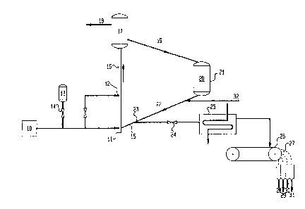
Referring to the Figures, FIG. 1 shows the metal distribution on the
10 particulates indicating that those portions of the particulates which are
highest in
metal content have generally been in the unit for the longest period of time
and have
lost much of their catalytic or sorbent ability. Selective removal of these,
of course,
increases the activity of the remaining catalyst and/or sorbent and this is a
major
object of the present invention.
FIG. 2 shows a simplified schematic diagram of a typical riser
conversion system in which a reduced crude flows into the riser at injection
point 11 and/or 12 after having been injected with a portion of ferric sulfate
from tank 13. The flow of ferric sulfate is controlled by valve 14 so that the
iron will be 1-5 pprn times the nickel equivalent ppm deposited on the
catalyst
circulating in the system. Regenerated catalyst flows through line 15 into
riser
reactor 16 where it meets the feed at injection point 11 which contains about
one ppm vanadium, one ppm nickel, and one ppm iron for a total metals
content of 1.3 nickel equivalents. The catalyst and feed flow in plug-flow,
taking about 1.5 seconds to reach separator 17 where the cracked vaporous
products
CA 02072636 2002-06-14
11
18 are separated from the catalyst now contaminated with vanadium, nickel and
iron
for a total nickel equivalents in the equilibrium catalyst of about 1000 ppm
nickel
equivalents. The spent catalyst 19 flows through conduit 19 into the
regenerator 20
where it is regenerated with air 21 which burns off the coke. Hot regenerated
catalyst
flows through line 15 into separator 23 in which valve 24 is set to remove
about 25
percent by weight of the catalyst flowing through conduit 22. The remaining
catalyst
returns to the riser for contact with further feed. The catalyst is separated
out where it
flows through cooler 25 and onto magnetic separator 26 then past magnetic
roller 27
which separates the more magnetic portions from less magnetic portions into
four
separate portions each more magnetic than the next (28, 29, 30, 31 are each
successively less magnetic). The number of portions returned to the catalyst
make-up
injection inlet 32 to be mixed with fresh make-up catalyst and recycled
through the
system, is dependent on the particular operating characteristics of the system
with the
particular feed and catalyst being employed. Generally the most magnetic 80%,
more
preferably 50%, and most preferably 30 or lower weight percent of the catalyst
will be
discarded and the remainder recycled back through catalyst make-up inlet 32.
The
microactivity test (MAT) activity, as measured by the usual standard tests,
indicates
that the more magnetic portion which is discarded has a MAT activity (as
defined in
U.S. Pat. No. 4,536,281, FIG. 14) which is substantially lower and a metals
content
which is substantially higher than the other portion, which is recycled.
Discarding the
more magnetic portion raises the activity of the total equilibrium catalyst
charge in the
system and substantially reduces the amount of make-up catalyst required to be
added
periodically.
FIG. 3 shows a section view of a portion of the riser 16 showing
magnetic particles (solid black), less magnetic particles (white circles), and
vapors
WO 91/12Z98 '",,~'~'~,.'ah«~ 12 PCT/US91/00484
1 "'
(indicated by wavey vertical lines) moving in plug flow
up the riser. The particles may be sorbent or catalyst
4 or both intermixed. The average metal on catalyst of
the non-magnetic particles is usually 50-90% of the
average metal content of the magnetic particles and
preferably 60 to 85%.
a
Referring to Figures 4-6, these show that the
addition of iron, conventionally thought to be highly
deleterious, has little effect on coke-make, gasoline
~2 selectivit and h dro en-make
y, y g (gasing), respectively.
14
Figure 7 shows that the more magnetic portions
discarded from the system shown in Figure 2 are high in
vanadium and in iron, and somewhat higher in nickel. It
is an important feature of the invention that, contrary
i9 to the mathematical expression for nickel equivalents
2o which is conventionally employed, vanadium has been
2~ found to be even more del eteri ous than ni ckel , and i is
22 removal from the system substantially enhances the
23 catalyst life and reduces the need for make-up catalyst.
24
25 Temperature:
26
2~ Though not narrowly critical, temperature can be
28 used to enhance the process because magnetic
2s susceptibility increases as temperature decreases, with
3o most materials. Preferred temperature ranges are about
31 -200°F to +400°F, more preferably 100°F to
400°F, and
32 most preferably -50°F to +250°F.
33
Magnetic Split and Recycle:
3s With most crudes and catalyst it is preferable to
3~ discard from about 1-30, more preferably 3-25, and most
38 preferably 5-15 wt. % of the regenerated catalyst to the
39 magnetic. separator. The wt. % sorbent rejected by the
magnetic separator is preferably from about 5-50, more
CA 02072636 2002-06-14
13
preferably about 10-35, and most preferably 15-30% by weight. Economics,
desired
MAT activity and other factors will affect the optimum split. Discarded
catalyst may
be processed for metal recovery where economical. Remaining catalyst and
sorbent is
preferably recycled to the same or another conversion system.
Example 1
Referring to FIG. 2, reduced crude representing the bottoms derived from
distilling off a portion of crude oil 10 enters the riser reactor at 11 after
mixing with a
metal additive of tank 13. In the riser the reduced crude contacts regenerated
catalyst
returning from the regenerator line 15 and travels up the riser 16 cracking
the reduced
crude and generating product 18 and spent catalyst 19 which is contaminated
with
coke and metals from the reduced crude. The spent catalyst 19 flows into the
regenerator 20 and is oxidized with air 21 to burn off coke and thereby
regenerate the
catalyst for return to the riser 16. About 8% of the regenerated catalyst is
diverted
through valve 24 to catalyst cooler 25 and to feed to magnetic separator 26,
where it
moves past roller 27, a high intensity rare earth-containing permanent
magnetic roller
which splits the catalyst into two or more portions 28 to 31. The more
magnetic (more
metal-contaminated) portions, e.g. 28, and/or 28 and 29 are rejected for
chemical
reclaiming, metals recovery, or disposal. The less magnetic (less metal-
contaminated)
portions 30 and 31 travel through line 33 back to the regenerator 20.
Table I shows an analysis and is a typical example of an equilibrium catalyst
withdrawn from a fluid bed operation on a high metal containing reduced crude.
WO 91 / 12298 ~ ' ~~ ,~ PGT/US91 /004tt4
2~''7... ~..~ , > 14
TABLE 1
3 ANALYSIS OF A TYPICAL EQUILIBRIUM REDUCED CRUDE
CATALYST WITH HIGH IRON CONTAMINATION
Iron 1.12 wt. %
Nickel 0.19 wt. %
Vanadium 0.41 wt. %
8
Example 2
~o
» Table 2 shows results from a residual processing
~2 run in which the iron level was 6900 ppm on spent
~3 equilibrium conversion (ACC process) catalyst processing
~4 reduced crude. The results of magnetic separation on a
~5 Rare Earth Roller Magnetic Separator (REAMS) are shown
in Table 2. .
TABLE 2
RCCsm - Spent Catalyst
2~ Untreated Magnetically Separated Product
22 Sample NMag Mid Mid Mid Mag
23 yield, Wt.% - 24.6 21.3 18.7 17.4 18.0
24 Vanadium, Wt.% 0.37 0.31 0.34 0.36 0.39 0.46
Nickel, Wt.% 0.12 0.10 0.12 0.13 0.15 0.20
Iron, Wt.% 0.69 0.64 0.67 0.70 0.72 0.87
26 Carbon, Wt.% 1.06 1.26 1.14 1.04 0.95 0.87
2~ Surface Area,
28 m2/g 84 88 85 80 76 71
29 Ratio V/Fe 0.54 0.48 0.51 0.51 0.54 0.53
Ratio V/Ni 3.1 3.1 2.8 2.8 2.6 2.3
3~ In this example iron concentration varies from 6400
32 ppm at the non-magneti c 1 ow metal 1 evel to 8700 ppm at
33 the highest level, for an increase of 2300 ppm, while
34 nickel increases from 1200 ppm to 2000 ppm (an increase
of 800 ppm) . Thus, iron beneficiation is 2.9 times as
3s great as Ni beneficiation. Obviously, beneficiation
3~ (separation) is, in a major way, dependent on the
3$ magnetic properties of the iron content.
39
CA 02072636 2002-06-14
Example 3
Table 3 shows results from essentially the same catalyst as example 2 after
being regenerated under commercial operating conditions, wherein catalyst
which
contains 7100 ppm iron is subjected to magnetic separation. The separation
shows an
5 increase from 5800 ppm iron in the non-magnetic portion to 8800 ppm iron in
the
high magnetic portion, an iron beneficiation of 3000 ppm. Nickel, on the other
hand,
present at 1400 ppm in the untreated sample, is 800 ppm in the non-magnetic
portion
and 1900 ppm in the magnetic portion, for a nickel beneficiation of 1100 ppm.
Again
there is an Fe/Ni beneficiation ratio of 2.7, showing again the effectiveness
of iron in
10 facilitating separation.
TABLE 3
RCCS"' - Regenerated Catalyst
Untreated Nmag Mid Mid Mid Mag
Sample 2X1 2X2 ZX3 2X4 2X5
15 Yield, Wt. - 11.7 17.9 42.111.6 16.7
%
Vanadium, Wt. 0.36 0.26 0.34 0.350.40 0.44
%
Nickel, Wt. % 0.14 0.08 0.13 0.120.16 0.19
Iron, Wt. % 0.71 0.58 0.67 0.680.76 0.88
Carbon, Wt. % 0.05 0.08 0.05 0.050.05 0.05
Surface Area,
m2/g 97 113 94 92 89 81
Ratio V/Fe 0.51 0.45 0.51 0.510.53 0.50
Ratio V/Ni 2.6 3.3 2.6 2.9 2.5 2.3
Example 4
Table 4 shows results from a run on an Engelhard ARTCATR sorbent
from the (ART) process. The ART process is a process developed for asphalt
and metal removal from reduced crude in a fluid bed contacting operation (See
U.S. Pat. Nos. 4,263,128, 4,243,514 and 4,256,567). Here the iron level
at the low magnetic end is 5700 ppm for an ARTCATR sorbent
containing 8200 ppm iron, while the high magnetic end contained iron at
WO 91 / 12298 ~ PGT/US91 /004Ra
1 2('~'7~E~ ~~i 16
2 12200 ppm for an iron beneficiation of 6500 ppm.
3 Nickel, with a 3200 ppm level in equilibrium material,
4 increases from 2100 on the low magnetic fraction to 4000
ppm in the high magnetic side, showing a nickel
s beneficiation of 1900 ppm, compared with iron with an
increase of 6500 ppm. Here again, the ratio of Fe/Ni
beneficiation is 3.4. Clearly, beneficiation is much
more readily achieved due to iron content than nickel
content.
11
12
TABLE
4
13
14
MRS Sorbent
1s
Untreated
17 Sample NMag Mid Mid Mid Mid Mag
18
Yield, Wt.% - 16.6 16.6 16.6 16.6 16.6 16.6
19 Vanadium, 0.88 0.90 1.17 1.49 1.56 1.52
Wt.% 1.07
Nickel, Wt.%0.32 0.27 0.31 0.38 0.35 0.39 0.44
21 Iron, Wt.% 0.82 0.70 0.71 0.83 1.04 1.16 1.28
22 Ratio V/Fe 1.3 1.3 1.3 1.4 1.4 1.3 1.5
23 Ratio V/Ni 3.3 3.2 2.9 3.1 4.3 4.0 3.5
24 Example 5
2s This example show that iron has little or no effect
2~~ on catalyst performance. The data is taken from
28 commercial operation on an RCC residual crude processing
2s unit, during a period when iron level on catalyst is at
10,330 m as a result of
31 pp processing high iron
contaminated crude. In a similar run, iron level is
32 maintained at 7200-7500 ppm. For both of these periods,
33 nickel and vanadium content are quite similar.
34 Comparison of runs made at low and high iron levels,
each over a period of two weeks is shown in Table 5.
3s The results show that even though there is about 3000
ppm more iron on the high iron catalyst during the high
38 iron two week period, there is little change in
conversion or asoline efficient and the
4o g Y yields of all
.)~~r. ~( ,
IGi .,. ~<.n.)v~)
WQ 91/12298 1~ PCT/1JS91/40484
1
products compare very closely. The resultant coke make
3 (wt. % coke - Ramsbottom Carbon) = 5.2 wt. % and 5.8 wt,
4 % respectively for the two weekly low iron runs, and 5.2
wt. % and 5.0 wt. % for the two high iron runs. This
shows that the additional iron does not cause an
p g y, increasing
7 increase in coke make. H2 is a sli htl
about 20 SCF/bbl. for the higher metal catalyst.
However, nickel, a notorious hydrogen producer and
vanadium, a less active hydrogen producer, are both up
(approximately 300 to 500 ppm nickel and 600 ppm
~2 vanadium). Contrary to conventional wisdom, this data
'3 shows that adding large amounts of iron to the catalyst
'4 is not detrimental to catalyst activity or yield of
'S valuable products (selectivity). Therefore,
intentionally adding iron in order to increase iron
'7 content, and thereby enhance magneti c benef i ci ati on, i s
shown to be technically sound. Note also that even the
'9 expensive virgin catalysts used in commercial
2o hydrocarbon conversion operations start out with natural
2' iron levels of 3000 to 4500 ppm (kaolin clay component)
22 and further confirms that iron is not considered harmful
23 even in expensive sophisticated fresh conversion
24
catalysts.
2s TABLE 5
27
28
IRON
2s PPM
3~ Iron Content 72-7500 ppm 10330-10930 ppm
2 wk. period 2 wk. period
32
33 RCC DATA
DATE (A) Week #1 Week #2 Week #3 Week #4
34 Avg . Avg .
T~~ CHG.B/D 32460 31900 38130 37430
36 Conversion Total 67.4 68.8 68.1 68.2 69.9 69.0
37 Gaso. Efficiency 73.5 73.1 73.3 69.8 75.9 72.9
Yfelds:Dry Gas wt% 3.7 4.0 3.8 3.7 3.9 3.8
38 DRY GAS-FOE vol% 4.0 4.1 4.1 4.1 4.3 4.2
39 C3-C4 vol% 22.9 23.0 23.0 24.7 20.6 22.7
C5-430 EP vol% 49.6 50.3 49.9 47.6 53.0 50.3
430-630 EP vol% 18.8 I7.0 17.9 19.7 18.8 19.2
630+SLURRY vol% 13.8 14.2 14.0 12.1 11.4 11.7
WO 91/12298 iG~~~~~~ PCT/US91/004i~4
1 1g
2 COKE wt% 9.3 9.7 9.5 8.7 8.7 8.7
3 H2 scf/bbl 72 75 96 95
4 RX TEMP deg F 975 975 971 971
FEED to RISER degF 280 268 308 313
REGEN BED deg F 1333 1332 1331 1330
CAT/OIL RATIO#/# 7.5 7.5 8.2 8.3
Delta Coke-Wt% 1.24 1.29 1.07 1.05
7 SULFUR wt% 2.2 2.6 2.1 2.1
8 UOPK 11.5 11.4 12.0 11.7
RBC wt% 4.1 3.9 4.0 3.5 3.7 3.6
9 <650 degF -- -- -- --
CAT ANALYSES
Fe ppm 7500 7200 10930 10330
11 Ni ppm 1330 1500 1870 1870
12 V PPm 3630 3670 4270 4230
Feed N, ppm 5 6 6 NA
13 Feed V, ppm 6 8 16 NA
14
Example 6
1s
17 In this example, Table 6, commercial runs are both
18 of approximately 37000 barrel per day on a mixture of
1s vacuum bottoms, reduced crude, lube oil extract, vacuum
2o tower heavy gas oil and bulk distillate and are made in
21 consecutive weeks with iron rising 830 ppm in one week
22 (from 9500 to 10330 ppm) and nickel and vanadium
23 increasing only slightly. The results show that
24 conversion and gasoline efficiency are essentially
unchanged, with gasoline yield actually even slightly
2s higher at the higher metal level. Coke make (coke wt.
27 - RB carbon wt. %) was 5.0 wt. % for the higher iron
2$ catalyst, and was desirably lower than the 5.4 wt. % for
29 the lower iron level catalyst, thus again showing that
3o an increase in iron is not harmful. H2 increased, only
31 7 CF/bbl. an amount well within experimental error.
32
33 TABLE 6
34
36
37
38
39
2~."7~E~36
WO 91/12298 19 PCT/U591/00484
1
2
RCC DATA
4 Run 6A 6B
Higher Iron
Lower Iron
6
TOTAL CHG. B/D 37430 37020
WORF Feed 360 550
g VAC BTMS 4480 4300
Reduced Crude 11070 11600
No. 4 Vac Btms 0 0
1p Lube Plt Extract 3820 3480
LVT HVGO 6530 6240
11 Bulk Dist. 11170 10850
12 Trtd Fd-From MRS 0 0
Conversion-Total 69.9 69.4
13 Gaso. Efficiency 75.9 75.8
14 Yields: Dry Gas .-wt% 3.9 3.8
DRY GAS-FOE vol% 4.3 4.0
C3-C4 vol% 20.6 19.9
16 C5-430 EP vol% 53.0 52.6
430-630 EP vol% 18.8 20.2
17 630+SLURRY vol% 11.4 10.4
18 COKE wt% 8.7 9.5
VOLUME GAIN % +3.7 +3.1
19 H2 scf/bbl 95 88
H2/C1 RATIO 0.98 0.91
21 ~ TEMP deg F 971 971
FEED to RISER deg F 313 314
22 REGEN BED deg F 1330 1332
23 C02/CO RATIO 6.5 6.5
CAT/OIL RATIO #/# 8.3 8.2
24 Delta Coke -wt% 1.05 1.16
FEED GRAY-deg API 21.0 20.4
SULFUR wt% 2.1 2.3
26 UOPK 11.7 11.5
27 RBC wt% 3.7 4.1
<650 deg F -- --
28 CAT ANALYSES
29 Fe ppm 10330 9500
Ni ppm 1870 1750
V ppm 4230 3950
31 SA m2/g 114 121
Pv cc/g 0.29 0.28
32
33 Example 7
34
3s In another experiment,
80 grams of reddish
3s appearing (iron contaminated) librium catalyst
equi
3~ containing iron, nickeland vanadium having a similar
38 iron content (11,600 ppm) as used in the previous
3g example, is mixed thor oughly with gms. of grayish
20
4o white colored virgin Corp. ) catalyst,
F0C-90 (Filtrol
r ,ryr .
iG l_. ~ ~.?. f ~..; . o
WO 91/12298 2p PCT/US91/004fw
containin a roximatel 4,000
g pp y ppm of iron and
essentially no nickel. The mixture is subjected to
4
magnetic separation by processing over a rare earth
roller magnetic separator, with a steel belt (to
s eliminate or reduce electrostatic charge which
7
interferes with magnetic separation) (0.00311 thick) 6"
wide, at a speed of 150 fpm feet/minute, and 5 lb/hr/in
of bel t wi dth wi th a spl i tter p1 aced to properly catch
» the two fractions. Two portions, (1) 19.8 gms. of
absolutely clean grayish white virgin catalyst, and (2)
80.2 gms. of reddish high iron catalyst were recovered
~4 from the mixture after magnetic processing. This shows
the effectiveness of the magnetic separation method.
is Table 7 shows the composition of both fractions before
mixing, and after separation, and strikingly
demonstrates how a high concentration of iron in old
catalyst can almost completely achieve magnetic
2o separation from new fresh catalyst for recycle and
2~ rejection of old catalyst for disposal. This experiment
22 ideally illustrates how effective magnetic beneficiation
23 can be.
24
25 This experiment not only demonstrates how efficient
2s magnetic separation can be (1% loss of virgin catalyst)
27 but also how clean the separation can be. It is
28 apparent that the composition of the two fractions
29 remain essentially the same as before blending,
3o confirming an absence of cross carryover. Comparison of
3~ the color of the two ingredients before mixing and afte r
32 separation also showed them to be identical, a dramatic
.33 demonstration of the effectiveness of magnetic
34 separation.
3s ' TABLE 7
37
38
39
WO 91/12298 21 PCT/US91/004$4
1
SEPARATION OF BLENDED VIRGIN AND EQUILIBRIUM
REDUCED CRUDE CATALYST
4
1. Blended mixture of 20 wt.% FOC-90, 80 wt.%
Equilibrium RCC Catalyst analyses of each catalyst.
Pre mixture chemical an alyses
8
9
Fe ppm Ni ppm V ppm
11 Virgin FOC-90 4,800 300 <100
Equil. RCC Cat 11,200 1,900 4,300
12
1s 2. Recovery -- Recovered fractions- ChemicalAnalysis
14
Fe ppm Ni ppm V ppm
1g 19.8 wt.% NM portion (FOC-90) 4,900 300 <100
80.2 wt.% M portion (RCC Cat) 11,600 1,900 4,100
18
1s Example 4
21 In ARTCATR sorbent, Example 4, analyses of the
22 products from splitting equilibrium catalyst by magnetic
23 separation into six equal cuts show also how iron and
24 vanadium maintain a close and constant relationship.
Normally vanadium, if not immobilized, will spread
2s rapidly from old catalyst particles to new catalyst
2~ particles, thereby rapidly shifting the relationship of
2$ vanadium to iron, as well as nickel. Therefore, the
2s rati o V/Ni i n the 1 ow magneti c, 1 ow ni ckel cuts shoul d
so be high relative to Ni in the high nickel, high magnetic
31 cuts. However, Figure 7 portrays the analytical
32 comparison of the various magnetic cuts of ARTCAT loaded
33 with nickel, iron and vanadium. The data in Table 4, as
well as the following Figure 7 show how closely iron and
as vanadium track each other in a 1.3/1 ratio, thus also
36 demonstrating iron's ability to immobilize vanadia under
optimized operating conditions. Note also in Table 4
38 that the ratio of vanadium to nickel is lower on fresher
as and lower metacontaining catalysts, and higher on old
catalyst. This therefore, suggests that iron tends to
WO 91/12298 '~~~~~~3~ 22 PCT/US91/004rs
1
immobilize vanadium as otherwise, as mentioned above
mobile vanadium from older catalyst particles would tend
4
to transfer to lower nickel containing newer catalyst
and thus increase the vanadium to nickel ratio as it
s
does in Tables 2 and 3 on RCC catalyst where the iron
7 level and more importantly the incremental iron level
(iron in equilibrium catalyst minus iron in virgin
catalyst) is much lower than in the ARTCATR sorbent.
~i
~2 Evidence obtained on spent RCC (Table 8) by
i3 Electron Spectroscopy Chemical Analysis (ESCA) analysis
~4 shows that vanadium can be maintained in a non-mobile
~5 form either by immobilization with iron or by keeping it
in a reduced plus four state by keeping a small amount
~7 of carbon on regenerated particulate. This plus four
i8 state is less detrimental to the molecular sieves on
i9 which most conversion catalysts are based. Iron's
2o ability to immobilize vanadium, while at the same time
2~ enhancing separation, provides another way of
controlling vanadium and adds another unexpected benefit
23 to use of iron.
24 TABLE 8
25 EQUILIBRIUM RCC CATALYST
26 VANADIUM VALENCE ANALYSIS BY ESCA
27
RCC Catalyst Relative Amounts*
28
29 V+3 V+4 V+5
1. Spent-as received 1.04% coke 1 5 1
30 2. Commercial regeneration 0.2%
coke 2 4 2
3. #1-reduced in H 385°C 1 hr
32 5 atm 2 2 6 2
33 4~ #1-lab regenerated in air
'34 1200°F 4 hrs 1 2 5
5. #4-lab regenerated plus H
35 385°C 1 hr
36 5 atm 1 10 1
37 *This data shows the relative (V+3, V+4, V+5)
3$ amount of each vanadium valence, as determined by
39 comparing the relative areas under specific and
WO 91/12298 23 ;~~'~ ~f; ;~ PC1'/US91/00484
characteristic vanadium valence peaks as measured
3
by ESCA analysis.
The above results show that operation, vanadium
in
s if maintained in a slightlyreduced state (0.2% coke
on
7
regenerated RCC Catalyst) tends exist in the plus
to
four valence state, and the datashows, is retarded
as
in redispersing from one
catalyst particle to another.
i0
ii
i2 In studying magnetic separation on ARTCAT (Figure
~3 2, Table 4), iron and vanadium are closely paired.
suggesting iron is forming a ferrous compound with four
valence vanadium. Vanadium having a plus four valence
may form an immobilizing compound with iron, probably
Fe+2 because of the reducing environment. Hence, the
combination of adding iron and keeping a small amount of
i9 coke on regenerated catalyst, may also be especially
2o effective in controlling vanadium. In effect, the
2~ addition of iron not only assists in magnetic
22 separation, but simultaneously may serve to control the
23 zeolite destructive properties of vanadium in cracking
2a catalysts.
2s Example 9
27
2$ In the past when operating on gas oil in the
2~ preriser, prezeolite cracking era, iron was always
3o considered an undesirable poison, along with nickel,
vanadium, and copper. Today, using the latest
32 hydrocarbon conversion technology, including a much more
33 active zeolite promoted and stable catalyst, lift gas
as and a very short contact time riser reactor, catalytic
cracking of carbo-metallic feedstocks appears not to be
3s substantially hurt by iron. Taking the results of 116
37 weight balance tests on a reduced crude converter over a
3$ six year period and plotting selectivity, hydrogen, and
39 coke make versus iron content, and making a regression
ao analysis of all data shows that selectivity (yield of
WO 91/12298 , - , . 24 PGT/US91/OOe°a
2 gasoline - divided by conversion) remains at 74% with
iron ran in between 6,000 to 11,000
4 9 9 ppm as shown in
Figure 5. Hydrogen make, a sensitive measure of
contamination, also remains constant at 0.15 wt.
s between 6,000 and 10,000 ppm and actually decreases
sli htl at 11,000
g y ppm (see Figure 6). Coke make, which
is also considered a sensitive measure of metal
poisoning, actually decreases from approximately 10.7
wt. % at 6,000 to 9% at 11,000 ppm (see Figure 4).
11 These wei ht balances are
12 g performed over a six-year
period and include runs on a variety of residual
13
feedstocks varying widely in metal content and
14
1s Ramsbottom Carbon. The data confirm that iron is not
1s harmful, and therefore can be used successfully in
enhancing magnetic beneficiation.
18
19 Example 10
21 Magnetic susceptibility measurements can be made on
22 catalyst containing varying amounts of iron and nickel
23 and including iron on virgin catalyst. Figure 8 shows
24 that a plot of incremental magnetic susceptibility in
electromagnetic units can be plotted as a direct
2s relationship between incremental iron, plus nickel.
2~ When the data is broken down into the contribution of
28 nickel and iron (note the change in slope for three
z9 different catalysts, with varying amounts of nickel and
3o iron in Figure 8) as determined by a plot of atomic
31 fraction of each (Figure 9), it shows that iron has a
32 susceptibility value of 225x10-6 emu's at 100% iron, and
33 nickel has a magnetic susceptibility of 42x10-6 emu's at
34 100% nickel. Here again iron shows to be much more
3s effective, and in this case is 5-6 times as effective as
3s nickel in effecting beneficiation. This further
3~ confirms the effectiveness of the process.
38
39
CA 02072636 2002-06-14
Modifications
Specific compositions, methods, or embodiments discussed are intended to be
only illustrative of the invention disclosed by this specification. Variation
on these
compositions, methods, or embodiments are readily apparent to a person of
skill in the
5 art based upon the teachings of this specification and are therefore
intended to be
included as part of the inventions disclosed herein.
What is claimed is: