Language selection

Search

Patent 2073394 Summary

Third-party information liability

Some of the information on this Web page has been provided by external sources. The Government of Canada is not responsible for the accuracy, reliability or currency of the information supplied by external sources. Users wishing to rely upon this information should consult directly with the source of the information. Content provided by external sources is not subject to official languages, privacy and accessibility requirements.

Claims and Abstract availability

Any discrepancies in the text and image of the Claims and Abstract are due to differing posting times. Text of the Claims and Abstract are posted:

  • At the time the application is open to public inspection;
  • At the time of issue of the patent (grant).
(12) Patent: (11) CA 2073394
(54) English Title: SECTIONAL BOX WITH CORNER FORMING AND LOCKING ELEMENTS
(54) French Title: BOITE SECTIONNELLE AVEC ELEMENTS DE COIN POUR L'ASSEMBLAGE ET LE MAINTIEN DES COTES
Status: Deemed expired
Bibliographic Data
(51) International Patent Classification (IPC):
  • B65D 5/50 (2006.01)
  • B65D 1/22 (2006.01)
(72) Inventors :
  • BANDERA, LUIGI (Italy)
(73) Owners :
  • COSTRUZIONI MECCANICHE LUIGI BANDERA S.P.A. (Not Available)
(71) Applicants :
  • COSTRUZIONI MECCANICHE LUIGI BANDERA S.P.A. (Italy)
(74) Agent: MARKS & CLERK
(74) Associate agent:
(45) Issued: 2003-12-09
(22) Filed Date: 1992-07-08
(41) Open to Public Inspection: 1993-01-10
Examination requested: 1999-04-26
Availability of licence: N/A
(25) Language of filing: English

Patent Cooperation Treaty (PCT): No

(30) Application Priority Data:
Application No. Country/Territory Date
MI91 U 000632 Italy 1991-07-09

Abstracts

English Abstract


A sectional box with corner forming and locking elements
comprising a thermoformed plastics sheet element consisting of a
central panel element of quadrilateral shape the sides of which
are connected via preferential bending lines to four sides of
lateral panel elements which can be bent over box-like on the
central panel, in which on those sides extending from the corners
of the central panel element, the lateral panel elements are
provided with flanges which project outwards from the lateral
panel elements and are in total mutually facing contact when the
box is in its formed state,


Claims

Note: Claims are shown in the official language in which they were submitted.


6

The embodiments of the invention in which an exclusive property or privilege
is claimed
are defined as follows:

1. A sectional box with corner forming and locking elements, comprising:
a thermoformed plastics sheet element having a central panel element of
quadrilateral shape the
sides of which are connected via preferential bending lines to four sides of
lateral panel elements
which can be bent over box-like on said central panel;
on respective sides thereof extending from the corners of said central panel
element, said lateral
panel elements being provided with flanges which project outwards from said
lateral panel
elements and are in total mutually facing contact when the box is in its
formed state; and
a gripping and locking element being associated with said flanges;
wherein said gripping and locking element comprise a column having a central
vertical slot
defined by two shaped vertical walls;
wherein said two shaped vertical walls each extend from a respective region in
proximity to a
respective corner of said column, which has a cross-section in the form of a
right isosceles
triangle having two equal sides; and
wherein said two shaped vertical walls are maintained in position by a
plurality of horizontal
ribs extending from surrounding walls defined by said equal sides of said
isosceles triangle cross-
section.

2. A sectional box as claimed in claim 1, wherein:
at a lower end thereof said column also comprises a pair of vertical pin
elements arranged to be
inserted into corresponding holes provided almost in proximity to said corners
of said central
panel, and into further holes provided in turned-over portions also associated
with said central
panel in correspondence with said corners.

3. A sectional box as claimed in claim 1 or 2, wherein:
said flanges are welded together and in mutual contact.

Description

Note: Descriptions are shown in the official language in which they were submitted.


s~9 )t'.~,'fAi
i~o ~~~ ~y i.v ~ .,'~
- 1 -
SECTIONAL BOX WITH CORNER FOR"iiNG AND LOCKING ELEMENTS
This invention relates co a sectional box with corner forming and
locking el.:-ments.
In the packing and packaging of fruit and vegetables, the
container means used are in the form of wooden or plastics boxes
of various types and shapes, which although being sufficiently
strong and of low cost present problems in terms of their
transport when empty and their possible recovery.
If they are collected in one region for transportation to or use
in a region distant from the first, these problems are more deeply
felt and aggravate utilization costs and times.
To obviate these drawbacks, sectional thermoformed plastics sheet
boxes have been proposed which pan be assembled and then locked in
their assembled state by pin elements insertable through suitable
holes in parts of the bax as thermoformed.
This system is however rather complicated to use and suffers from
alignment and insertion problems during assembly.
An object of the present invention is to solve the aforesaid
20' problems by jeans of'a sectional box also obtained by plastics
thermoforming but being very simple to construct and assemble.
A further object is to provide a box of the aforesaid type which

CA 02073394 2003-02-25
is of low cost and is easily transportable within an extremely small space.
These objects are attained according to the present invention by a sectional
box with corner
forming; and locking elements comprising a thermoformed plastics sheet element
consisting of a
central panel element of quadrilateral shape the sides of which are connected
via preferential
bending; lines to four sides of lateral panel elements which can be bent over
box-like on said
central panel, characterised in that can those sides extending from the
corners of said central panel
element, said lateral panel elements are provided with flanges which project
outwards from said
lateral panel elements and are in total mutually facing contact when the box
is in its formed state.
More specifically, the present invention provides a sectional box with corner
forming and locking
elements, comprising a thermoformed plastics sheet element having a central
panel element of
quadrilateral shape the sides of which are connected via preferential bending
lines to four sides of
lateral panel elements which can be bent over box-like on the central panel,
on respective sides
thereof extending from the corners c>f' the central panel element, the lateral
panel elements being
provided with flanges which project out~.vards from the lateral panel elements
and are in total
mutuall;,~ facing contact when the be>x is in its fornted state, and a
gripping and locking element
being associated with the flanges, wherein the gripping and locking element
comprise a column
having a central vertical slot defined by two shaped vertical walls, wherein
the: two shaped
vertical walls each extend from a respective region in proximity to a
respective: corner of the
column, which has a cross-section in the form of a right isosceles triangle
having two equal sides,
and wherein the two shaped vertical walls are maintained in position by a
plurality of horizontal
ribs extending from surrounding walls defined by the equal sides of the
isosceles triangle cross-
section.
The structural and functional characteristics and advantages of a sectional
box according to the
present iinvention will be more apparent from the description of one
embodimc;nt thereof given
hereinafter by way of non-limiting example with reterence to the accompanying
drawings, in
which:
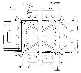
Figure 1 is a plan view of a sectional box according to the invention in plane
development;
Figure 2 is a partly sectional plan view of one half of an assembled box of
Figure 1;
Figure 3 is an elevational view of a connection element for the flanges
projecting from the
corners of the box of Figure 1;
Figure 4 is an enlarged detailed view of a corner of Figure 2;
Figure 5 is a section on the line V-V c>f Figure 4 of the c:onneccion element,
which is only partly
shown; and


- 3 -
ar Fa1 ~ wed
~~ ~ ..~~~W
Figure 6 is a partly sectional plan view of one half of an
assembled box of Figure 1, welded at its corners.
The figures show a thermoformed plastics sheet element indicated
overall by 10 and consisting essentially of several variously
shaped panel parts articulatedly joined together.
The thermoformed element constitutes the plan development of the
sectional box and comprises a central panel element 11 of
quadrilateral shape, this being rectangular in the example, and
four lateral panel elements 12 and 13 arranged in equal and
opposite pairs. These panel elements comprise for example ribs,
material cut-outs and various holes which stiffen them
individually in addition to lightening them. In addition, the
lightening cut-outs allow an immediate recovery of part of the
material, which is returned to the production cycle and used to
form further boxes, with maximum and optimum utilization of the
entire material. i
The central panel element 11 and the lateral panel elements 12 and
l3 are connected together via preferential bending lines l4 and 15
respectively, these also being formed during the thermoforming.
The four lateral panel elements 12 and 13 can be bent over to form
a box with the central panel 11 and are provided, on those sides
extending from the corners,bf the central panel elemeztt 11, with
flanges l7 and l8 which project outwards from the lateral panel
elements. When the lateral panel elements 12 and 13 have been
bent over relative to the central panel 1l so that they lie side
by side to form the box, these flanges assume a vertical position
relative to the horizontal central panel and can be brought


_ 4 _
together so that parallel portions are in mutual contact.
When the flanges 17 and 18 have been brought into mutual contact
as stated, they are inserted into a gripping and locking element
consisting of a column 19 with a central vertical slot 20 defined
by two shaped vertical walls 21.
The shaped walls 21 extend from a region in proximity to the
corner of the column 19, which has a cross-section in the form of
a right isosceles triangle. The two walls 21 are maintained in
position by a plurality of horizontal ribs 22 extending from
surrounding walls 23 defined by the equal sides or catheters of
the isosceles triangle.
At its lower end this column comprises a pair of vertical pin
elements 24, which are to be inserted into corresponding holes 25
provided almost in proximity to the corners of the central panel
11, and into further holes 26 provided in turned-over portions 27
also associated with the central panel 11 in correspondence with
its corners. The pin elements 24 and the holes 25 and 26 hence
act as a centering system and also partly cooperate in locking the
parts together.
A sectional box according to the present invention can be
assembled very rapidly from its flat transport and storage
position by simply inserting the flanges l7 and l8 into the slot
20 in four column elements 19. The particular shape of the slot
20 and the provision of stiffening ribs 22 on the column 19 result
in optimum locking of the flanges 17 and 18 which are inserted
into them and compressed together..
When it has been used for containing and transporting products,


~a:a ~un
~'~'i ~'~~'~~~
- 5 -
the box can be again broken down into the flat part and its corner
locking elements, allowing considerable ease of transport. In
this respect, the advantage of stackability to minimum bulk within
small spaces is achieved.
Alternatively and advantageously, if the box .is not to be reused,
instead of using the corner locking columns the corner flanges can
be joined together when in mutual contact. Figure 6 shows how two
contacting flanges can be welded together, for example using
ultrasound, to form the box according to the invention.
J

Representative Drawing
A single figure which represents the drawing illustrating the invention.
Administrative Status

For a clearer understanding of the status of the application/patent presented on this page, the site Disclaimer , as well as the definitions for Patent , Administrative Status , Maintenance Fee  and Payment History  should be consulted.

Administrative Status

Title Date
Forecasted Issue Date 2003-12-09
(22) Filed 1992-07-08
(41) Open to Public Inspection 1993-01-10
Examination Requested 1999-04-26
(45) Issued 2003-12-09
Deemed Expired 2005-07-08

Abandonment History

There is no abandonment history.

Payment History

Fee Type Anniversary Year Due Date Amount Paid Paid Date
Application Fee $0.00 1992-07-08
Registration of a document - section 124 $0.00 1993-08-17
Maintenance Fee - Application - New Act 2 1994-07-08 $100.00 1994-06-14
Maintenance Fee - Application - New Act 3 1995-07-10 $100.00 1995-06-23
Maintenance Fee - Application - New Act 4 1996-07-08 $100.00 1996-06-07
Maintenance Fee - Application - New Act 5 1997-07-08 $150.00 1997-06-18
Maintenance Fee - Application - New Act 6 1998-07-08 $150.00 1998-06-11
Request for Examination $400.00 1999-04-26
Maintenance Fee - Application - New Act 7 1999-07-08 $150.00 1999-06-16
Maintenance Fee - Application - New Act 8 2000-07-10 $150.00 2000-06-16
Maintenance Fee - Application - New Act 9 2001-07-09 $150.00 2001-06-22
Maintenance Fee - Application - New Act 10 2002-07-08 $200.00 2002-06-25
Maintenance Fee - Application - New Act 11 2003-07-08 $200.00 2003-06-19
Final Fee $300.00 2003-09-23
Owners on Record

Note: Records showing the ownership history in alphabetical order.

Current Owners on Record
COSTRUZIONI MECCANICHE LUIGI BANDERA S.P.A.
Past Owners on Record
BANDERA, LUIGI
Past Owners that do not appear in the "Owners on Record" listing will appear in other documentation within the application.
Documents

To view selected files, please enter reCAPTCHA code :


To view images, click a link in the Document Description column. To download the documents, select one or more checkboxes in the first column and then click the "Download Selected in PDF format (Zip Archive)" or the "Download Selected as Single PDF" button.

List of published and non-published patent-specific documents on the CPD .

If you have any difficulty accessing content, you can call the Client Service Centre at 1-866-997-1936 or send them an e-mail at CIPO Client Service Centre.


Document
Description 
Date
(yyyy-mm-dd) 
Number of pages   Size of Image (KB) 
Description 1994-04-04 5 182
Representative Drawing 1999-03-11 1 24
Claims 2003-02-25 1 40
Representative Drawing 2003-06-18 1 15
Abstract 1994-04-04 1 22
Drawings 1994-04-04 3 99
Description 2003-02-25 5 186
Cover Page 2003-11-05 1 43
Cover Page 1994-04-04 1 19
Claims 1994-04-04 2 58
Assignment 1992-07-08 7 239
Prosecution-Amendment 1999-04-26 2 112
Prosecution-Amendment 1999-09-09 3 103
Prosecution-Amendment 2002-08-29 3 74
Prosecution-Amendment 2003-02-25 4 144
Correspondence 2003-09-23 1 31
Fees 1996-06-07 1 56
Fees 1995-06-23 1 57
Fees 1994-06-14 1 58