Note: Descriptions are shown in the official language in which they were submitted.
2073501
Device for connecting a flexible pipe
to a rigid tubular joining piece
Patents FR-A-l 558 355, DE-A-3 815 168 and DE-A-3
914 645 in particular already disclose a device for
connecting a flexible pipe on a rigid tubular joining
piece, such a device essentially comprising a rigid
tubular assembly fixed in tight manner to the end
of the flexible pipe, this assembly being provided
with sealing means and with assembly and/or locking
means cooperating with elements complementary of the
rigid joining piece. More precisely, the tubular assem-
10 bly fixed to the end of the flexible pipe comprisestwo coaxial rigid tubular elements disposed respectively
inside and outside the end of the flexible pipe, adapted
to receive the rigid joining piece. In the more particu-
lar case of the German Patents mentioned above, these
15 two tubular elements embrace the free end of the fle-
xible pipe in the form of a bead and simultaneously
ensure seal and mechanical strength of the assembly,
thanks to radial deformations revealing cylindrical
portions of different diameters on each of the inner
20 and outer tubular elements. Furthermore, in order
to ensure seal of the connection, an O-ring, capable
of coming into contact with the outer piece of the
rigid joining piece, is disposed in a housing made
on the inner surface of the inner tubular element
25 by its portion of larger diameter. The housing is
closed, towards the outside in the axial direction,
by a radial annular wall, connected to the outer tubular
element, whose inner diameter is substantially equal
to the inner diameter of the inner tubular element.
30 At least one of said tubular elements co~prises assembly
and/or locking means cooperating with complementary
~ 2- 2073501
means provided in register on the rigid joining piece.
The known connecting devices of the type in ques-
tion present several drawbacks despite their efficiency.
On the one hand, they comprise relatively heavy
and/or voluminous members, sometimes difficult to
place in position, which in practice prevent their
being used for certain applications, particularly
if the assembly must be effected by means of machines
such as robots, which can generally effect only transla-
tions.
On the other hand, and in consequence of thesefirst drawbacks, the known devices are relatively
expensive, both due to the nature or structure of
the parts which constitute them and to the time necessa-
lS ry for positioning them.
Finally, particularly in the case of the twoGerman Patents mentioned above, the fastening of the
rigid tubular assembly on the end of the flexible
pipe requires a considerable deformation of the latter,
in particular in order to reveal, inside said assembly,
a housing for the O-ring with the joining piece. Such
deformations may bring about creeping of the flexible
pipe, highly detrimental to the correct holding of
the device.
It may be recalled here that, in the particular
case of the hydraulic cooling circuits for vehicle
motors, the flexible pipes must be equipped, before
being connected together, with the tubular assembly
intended to be fitted and fixed on the rigid joining
piece; this latter itself generally forms a part of
an apparatus, such as a heat exchanger previously
placed in position. The operation of assembly of the
pipe and of its tubular end assembly as well as the
operation of connection proper must be as simple as
possible and necessitate only a number of parts as
2073501
--3--
small as possible. In particular, the addition or
manipulation of parts in the final phase of connection
must be avoided.
The numerous technical and commercial requirements
which have just been recalled have led Applicants
to seek a device for connecting a flexible pipe on
a rigid joining piece, of the type described in the
Patents cited above, which eliminates the drawbacks
thereof whilst presenting various advantages.
According to the invention, the cylindrical por-
tlons of larger dia~eter of the inner tubular element
and of the outer tubular elei~ent (constituting what
has been called "the tubular assembly" fixed to the
end of the flexible pipe), preferably made of thin
metal sheet, are located, in the radial direction,
opposite the terminal bead of the flexible pipe, whilst
the radial annular wall, closing the housing of the
O-ring, is a piece distinct from the inner tubular
element .
Thanks to these arrangements, the tight fixation
of "the tubular assembly" on the flexible pipe does
not require a considerable radial compression of the
latter, whilst allowing easy production of the housing
of the O-ring; these operations are effec~-ed at the
manufacturer's, at the same time as the production
of the locking means intended to cooperate with those
provided on the rigid joining piece. These latter
will preferably be of the type described in Applicants'
European Patent Application entitled: "Device for
locking two coaxial tubes" and published on 28th August
1991 under No. 443.895.
In this way, connection of the flexible pipe
on a rigid joining piece necessitates no added part
nor even any manipulation other than the simple fit
of the end of the flexible pipe on the rigid joining P/~
~ _4_ 207350 1
piece.
Another aspect of this invention i~ as follows:
A ronnection device between a flexible pipe having
S an outwardly exten~ing radial bead at the free end
thereof and a rigid ~ r joining piece fitted inside
the flexible pipe, the improvement comprising: a rigid
inner t~ lAr element, said inner tubular element formed
with first and ~0con~ cylindrical portion~ of different
diameters; a rigid outer t~h~ r element in space coAYi
relation with said inner t~h~lAr element, said outer
tubular element formed with first and ~econ~ cylindrical
portions of different diameters and spaced from and
cooperating with respective first and recon~ cylindrical
portions of said inner tubular element, said inner and
outer tubular elements embracing the radial bead of the
flexible pipe in the radial space defined by the outer
surface of the second cylindrical portion of said inner
tubular element and the inner surface of the second
cylindrical portion of said outer tubular element and
said inner and outer tubular elements embracing the
flexible pipe in the radial space defined by the outer
surface of the first cylindrical element of said inner
tubular element and the inner surface of the first
cylindrical element of said outer tubular element;
an annular radial wall secured to said outer tubular
element and depending radially inwardly therefrom and
terminating at an annular plane substantially aligned
with the first cylindrical portion of said inner tubular
element; and an o-ring adapted to contact the outer
surface of the rigid tubular joining piece and di&~Gscd
in a housing defined by the inner surface of the second
cylindrical portion of said inner tubular element and
said annular radial wall.
~ -4a-
2073~01
The invention will be more readily understood
and various secondary characteristics as well as its
advantages will appear in the course of the following
description of some embodiments with reference to
the accompanying drawings, in which:
Figure la and Figure lb are outside views, partial-
ly in axial section, of a connecting device according
to the invention before assembly thereof.
Figure 2 is a similar view of the device after
assembly thereof.
Figure 3 is a view on a larger scale of a detail
of assembly of the tubular end assembly of the flexible
pip~ .
Figure 4 is a view similar to Figure 2 in the
case of a variant embodim_nt.
If re~erence is firstly made to Figures l to
3, a device for connecting a flexible pipe l, for
example of rubber, and a rigid joining piece 2, for
example of plastics material, is shown. In the follo-
wing, it will be assumed that the rigid joining pieceis fixed on an apparatus which cannot be displaced
at the moment of connection.
Joining piec~ 2 is constituted by a cylindrical
part whose free end presents, in 1cnown manner, a bead
2a generally followed by a groove 2b of small depth.
The free end of the pipe l, intended to be fitted
on the joining piece 2, is equipped with a "tubular
assembly" essentially constituted by two rigid tubular
elements 3 and 4, coaxial and disposed respectively
inside and outside the pipe. These two tubular elements
ensure, under conditions which will be specified,
a suitable mechanical tightening of the end of the
pipe, which is thus rigidified as well as a sufficient
seal between the inner wall of the pipe and the inner
l~
~ 2073501
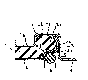
element 3.
Each of the two elenents 3 and 4 comprises two
c~lindrical portions 3a, 3b and 4a, 4b, of different
dianeters, the portions of larger diameter 3b, 4b
being located opposite the free end la of the pipe.
On the contrary, the portions 3a, 4a of smaller diameter
ensure radial tightening of the wall of the pipe and
their diameters are respectively at least equal to
the inner diameter of the pipe and at the most equal
to the outer diameter thereof. In addition, the inner
diameter of portion 3a is substantially equal to the
outer diameter of the bead 2a of the joining piece.
Portion 3b of larger diameter of the inner tubular
element 3 constitutes, towards the inside, a housing
5 for an O--ring 6 of app-opriate flexible material,
for example elastomer, whose inner diameter in the
free state is somewhat less than the outer diameter
of the joining piece 2. This portion 3b is preferably
connected to ~ radial wall 3c which extends substantial-
ly as far as the inner face of the portion of largediameter 4b of tho tubular element 4.
On the other hand, the two portions 3b, 4b of
la~ger dianeter of the two inner and outer tubular
elements define therebetween with the radial wall
3c, a cavity 7, open towards the left in the Figures,
imprisoning the free end la of the pipe which then
forms a bead whose diameter is somewhat larger than
that of the pipe. In that respect, it will be noted
here that the minimum width 1 of the passag~ between
the cavity 7 and the annular zone defined by the two
cylindrical portions 3a and 4a is slightly less than
the thic'~ness of this annular zone.
The housing 5 of the O-rin~ 6 is closed, towards
the outside in the axial direction, by an annular
wall 8 whose inner diameter -is substantially equal
~_ 2073501
.
--6--
to that of the cylindrical portion 3a. As clearly
shown in the Figures, the radial wall 8 is preferably
connected, in the direction opposite the pipe, to
a bush 9 whose inner diameter is, it too, substantially
equal to the outer diameter of the joining piece 2.
Finally, it will be noted that, at its in,ner
end, the inner tubular element 3 presents a shoulder
3_ directe;~ towards the inside, capable of constituting
an axial stop for the joining piece under conditions
which will be specified hereinafter. Moreover, at
least one hole 10 is provided in the portion 4b of
the outer tubular element 4 and opens out in cavity
7.
The tubular end assembly of the pipe, which has
just been generally described, may be made of any
appropriate material. However, as clearly shown in
the Figures, in particular in Figure 3, it is advanta-
geous to make it in thin metal sheet, which facilitates
manufacture and assembly thereof and limits the cost
thereof. Moreover, as will be readily realized, the
resultant dimensions of the connection remain very
small and correspond only to the outer diameter of
portion 4b.
After having fitted pipe 1 in the outer tubular
element 4 until its terminal face is located in the
portion 4b of large diameter, the inner tubular element
3 is fitted under known conditions, similar to those
described for example in French Patent A-l 434 683.
As clearly shown in Figure 3, the radial wall 8 fast
with its bush 9 has preferably been previously crimped
on the outer periphery of the radial wall 3c of the
inner tubular element 3.
The terminal bead la of the pipe is then imprisoned
in the cavity 7 and the tubular end assembly of the
pipe is terminated by the crimping of the free edge
~ 2073501
--7--
of the portion 4b on the outer periphery of the radial
wall 8. Hole 10 makes it possible to verify visually
the presence of bead la in cavity 7.
Finally, complementary means (not shown) are
provided on the one hand on the joining piece, on
the other hand on the tubula~ assembly, preferably
on the bush 9, in order to ensure me-hanical connection
of the two members, in the axial ,~irection. These
means will preferably be of the type described and
10 shown in the Patent Application ~iled by Applicants
this day and entitled: "Device for locking two coaxial
tube s " .
The man skilled in the art will, of course, already
have understood that connection of the pipe on the
joining piece is effected simply by displacing the
tubular assembly 3, 4 and its pip.- 1 towards the joining
piece 2 in the direction of arrow F of Figure 1.
In the course of this operation, bush 9 facilitates
guiding and th~ displacement in the direction of arrow
F continues until the end of the bead 2a comes into
abutmen-' on the shoulder 3d of the inner tubular element
3. After the O-ring 6 has passed over the bead 2a,
the effort necessary for displacement in the direction
of arrow F reduces abruptly due to the presence of
the groove 2b. Whatever the means, manual or motorized,
used for displacing the pipe, it then acquires an
inertia which facilitates positioning up to contact
of the stop 3d on the bead 2a and consequently the
cooperation, generally automatic, of the means (not
shown) for locking the tubular assembly and the joining
piece. In any case, tightness of the connection is
ensured by the contact of O-ring 6 and the outer surface
of joining piece 2, beyond groove 2b (Figure 2).
Such a connecting device is particularly adapted
to robotiz~ed assembly; however, it may very easily
~ 2073501
be pla-ed in position manually for example if it is
que~tion of a replacement piece. Much more, in this
latter eventuality, the well known shape of the joining
piece 2 and more particularly the presence of the
bead 2a and groove 2b make it possible directly to
fit a fle~ible pipe on the joining piece and to maintain
it by a known clamp.
If reference is now made to Figure 4, a variant
embodiment is seen in which the elements already des-
10 cribed bear the same references increased by 10. Thetubular end assembly of pipe 11, which, in its preceding
embodiment comprised three pieces 3, 4 and 8, comprises
no more than two designated by references 13 and 14.
In fact, the radial annular wall 18 closing the
15 housing 15 of the O-ring 16 constitutes one piece
with the outer tubular elei~ent 14 and is joined directly
to the portion of large diameter 14b.
Assembly of the tubular assembly 13-14 is slightly
different from that which ihas been described hereinabove.
The inner tubular ele~ent 13, suitably formed
with its shoulder 13d and its lateral wall 13c, is
firstly fitted in the free end of the pipe 11.
The tubular element 14, previou~ly shaped to
reveal the radial wall 18 and possibly the bush 19,
25comprises a cylindrical extension 14c (shown in inter-
rupted lines) of what will become its portion of larger
diameter 14b.
The cylindrical bush 14b-14c is fitted on the
right-hand end of the pipe 11 and covers the bead
30lla until the radial wall 18 is in abutment on the
inner tubular element 13.
A contraction operation then reduces the diameter
of portion 14c of the bush and reveals portion 14a
of the outer tubular element at the same time as bead
3511a of the pipe is imprisoned in cavity 17 under the
~, 2073501
conditions quite similar to those which were specified
hereinabove.
The operation of connection of pipe 11 on joining
piece 12 is, of course, efEected in the same manner
as that described regarding the first embodiment and
presents the same advantages.