Note: Descriptions are shown in the official language in which they were submitted.
` ~73~
APPARATU~ AND PROCE~ FO~ HDRAW~NG 8TRIPPBR
GA8 FRON AN FCC R~AC~OR V~E~
~D#78,523-Cl-F)
5CRO~-RB~ ~C~ TO RELAT~D APPLICA~ION
This application is a contimlation-in-part of Serial
No. 07~620,114 filed November 30, 1990, for Apparatus For
Withdrawing Stripping Gas From An FCCU Reactor Vessel to T. Y.
Chan, abandoned.
BACRGROIJND OF ~ VENl!ION
1. Fiel~l of the Invention
This invention relates to an apparatus for rapidly
separating catalyst from a cracked hydrocarbon gas in a fluidized
catalytic cracking (FCC) unit. The invention is also a process
for withdrawing stripper gas from an FCC reactor vessel.
2. Related Apparatus and Metho~s in the Field
The fluid catalytic cracking (FCC) process comprises mixing
hot regenerated catalyst with a hydrocarbon feedstock in a
transfer line riser reactor under catalytic cracking reaction
conditions. The feedstock is cracked to yield gasoline boiling
range hydrocarbon as well as degradation products, such as coke
which deposits on the catalyst causing a reduction in catalytic
activity. Hydrocarbon vapor and coked catalyst are passed from
the top of the riser reactor directly to a separator vessel
--1--
'
2 ~ 2
wherein catalyst is separated from hydrocarbon. In the FCC art,
the separator vessel is termed the reactor vessel. The eeparated
catalyst is passed to a stripper wherein it is contacted with a
stripping gas to remove volatile hydrocarbon. Stripped catalyst
is then passed to a separate regeneration vessel wherein coke is
removed from the catalyst by oxidation at a controlled rate.
Catalyst, substantially freed of coke, is collected in a
vertically oriented regenerated catalyst standpipe. The catalyst
is passed from the standpipe to the riser reactor for cyclic
reuse in the process.
A conventional feedstock comprises any of the
hydrocarbon fractions known to yield a liquid fuel boiling range
fraction. These feedstocks include light and heavy gas oils,
diesel, atmospheric residuum, vacuum residuum, naphtha such as
low grade naphtha, coker gasoline, visbreaker gasoline and like
fractions from steam cracking.
CataIyst development has improved the fluid catalytic
cracking (FCC~ process. The fluid catalytic cracking process has
been modified to take advantage of high activity catalysts,
particularly crystalline zeolite cracking catalysts, to take
advantage of the high activity, selectivity and feedstock
sensitivity of these catalysts. These high activity catalysts
has been used to improve the yield of more desirable products
from feedstocks.
~73~
The hydrocarbon conversion catalyst employed in an FCC
process is preferably a high activity crystalline zeolite
catalyst of a fluidizable particle size. The catalyst is
transferred in suspension or dispersion with a hydrocarbon
feedstock, upwardly through one or more riser conversion zones
which provide a hydrocarbon residence time in each conversion
zone in the range o~ 0.5 to about 10 seconds, typically less than
about 8 seconds. High temperature riser hydrocarbon conversions,
occurring at temperatures of at least soooF up to about 1450F,
pressures of 5 psig to 45 psig and at 0.5 to 4 seconds
hydrocarbon catalyst residence time in the riser are desirable.
The vaporous hydrocarbon conversion product is rapidly separated
from the catalyst.
Rapid separation of catalyst from hydrocarbon product
is particularly desirable to constrain hydrocarbon conversion
time to the residence time in the conversion 20ne. During the
hydrocarbon conversion, coke accumulates on the catalyst
particles and entrains hydrocarbon vapors. Entrained hydrocarbon
contact with the catalyst continues after removal from the
hydrocarbon conversion zone until the hydrocarbon is separated
from the catalyst. The separation is typically by cyclone
separating followed by stripping the catalyst with a stripping
gas to remove volatizable hydrocarbon. Hydrocarbon conversion
products and stripped hydrocarbon are combined and passed to a
~ .
2~73~
fractionation and vapor recovery system. This system comprises a
fractionation tower, vapor coolers and wet gas compressor
operated at a suction pressure o~ 0.5 to 10 psig. Stripped
catalyst containing deactivating amounts of coke, is passed to a
catalyst regeneration zone.
Cyclone separators are used to separate fluidized
catalyst particles from cracked hydrocarbon. In a typical
cyclone separator, a suspension of hydrocarbon vapor and
entrained finely divided solid particulate catalyst is introduced
tangentially into the separator barrel. In the barrel a spiral,
centrifugal motion causes the solid particles to be thrown to the
wall of the cyclone separator where they flow downward under the
force of gravity to a catalyst bed. Separated vapor is removed
through an axial vapor withdrawal conduit extending below the
tangential inlet conduit upwardly through the top of the cyclone
separator. A vapor recovery system, in fluid communication with
the vapor withdrawal conduit, is maintained at reduced pressure
to assist the withdrawal of vapor from the cyclone separator.
An object of the present invention is to provide an
apparatus particularly suited for rapidly separating the
catalyst-hydrocarbon suspension. Another object is to establi h
a stable pressure gradient between the cyclone barrel and the
reactor vessel to facilitate removing stripper gas from the
. ; ~
.
~73~
reactor vessel. Ano~her object of this invention is to provide a
cyclone separator apparatus which withstands thermal expansions.
Perry's Chemical Engineers' Handbook, 4th ed., pp. 20-
68 to 20-71 describes general design parameters for cyclone
separators used for removing solid particles from vapors.
Kirk-Othmer Encyclopedia, 3rd ed., Vol. 1, pp. 667 to
672 describes general design parameters for cyclone separators
used for separating solid particles from gases.
U. S. Patents 4,623,446 and 4,737,346 to J. ~. Haddad
et al. teach a closed coupled cyclone separator system in the
reactor vessel of a fluid catalytic cracking apparatus. Means is
provided for blending stripping gas with cracked hydrocarbon as
it flows to a directly coupled riser cyclone separator. As shown
in Fig. 7 and 8, the riser reactor conduit is modified to
comprise an overlapping downstream portion 118 to provide an
annulus between the upstream portion 117 and the downstream
portion 118. The annulus is covered by a flat metal ring having
orifices 125 in open communication with the reactor vessel,
enabling stripping gas to pass into the downstream conduit 118.
A riser cyclone dipleg is sized, as seen in Fig. 5, to admit at
least a portion of stripping gas from the stripping zone to pass
countercurrent to catalyst passing downwardly through the dipleg.
U.S. Patent 4,502,947 to Haddad et al. discloses a
closed cyclone ~luid catalytic cracking catalyst separation
:
, ~
,~ '
2~7~3~,
method and apparatus. In the closed cyclone, hydrocarbon product
and catalyst are passed directly into a cyclone separator from a
riser without passing into the atmosphere of the reactor vessel.
Avoiding the atmosphere of the reactor vessel reduces both excess
catalytic cracking and high temperature thermal cracking.
BRIl~F 8U~RY OF T~ 13NTION
The invention is an apparatus for the fluid catalytic
cracking of a hydrocarbon feedstock. The apparatus comprises a
vertically elongated tubular riser reactor having an upstream end
and a downstream end, the downstream end terminating within the
reactor vessel. Means is provided for introducing a suspension
of hydrocarbon feedstock and catalyst into an upstream end of the
riser reactor wherein the hydrocarbon fePdstock undergoes
cracking reactions. The cracked hydrocarbon feed and catalyst
mixture exits from the downstream end of the riser reactor. A
first conduit connects the downstream end of the riser reactor
directly to a riser (first) cyclone separator contained within
the reactor vessel.
In the riser (first) cyclone separator, an inlet duct
discharges into a vertically elongated cylindrical barrel. The
bas~ of the barrel is attached to an inverted conical member
which attaches to a vertically elongated catalyst dipleg for
conducting catalyst from the barrel to a catalyst stripper. The
'' ' ' ' ,
2~73~,L~.2
stripper comprises means for containing a stripping zone in the
reactor vessel and means for introducing stripping gas.
The upper end of ~he barrel has a ~op cover with an
annular port. The annular port is axially aligned with the
barrel and provides fluid communication between the reactor
vessel and the barrel. A vertically oriented outlet conduit
axially aligned with the barrel traversPs the cover through the
center of the port. The outlet conduit provides fluid
communication for cracked hydrocarbon out of the reactor vessel
by way of a secondary cyclone separator.
BRIE~ DE8CRIPTION OF THE DRAWING~
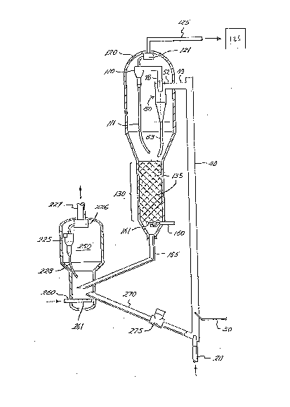
Fig. 1 is a diagrammatic arrangement of a fluid
catalytic crackiny apparatus comprising a riser reactor, a
reactor vessel, a catalyst stripper and a regenerator.
Fig. 2 is a proportional side view of a riser cyclone
separator.
D~TAI~BD DB8CRIPTIO~ OF THE INV~NTION
Reference is made to Fig. 1 which is representative of
an apparatus for contacting a hydrocarbon oil feedstock with
finely divided ~luidized catalyst in riser reactor 40 at
catalytic cracking conditions. A clean, freshly regenerated
catalyst is delivered from regenerated catalyst standpipe 270
, ,~ , .
. - .
2~7~2
into the lower portion of riser reactor 40. The regenerated
catalyst has a carbon content less than about 0.1 wt% and an ASTM
microactivity of 60 to 70 by ASTM D-3gO7 Microactivity Test (MAT)
or the equivalent. As the catalyst enters the riser, its
temparature is decreased from that of the regenerator by the
addition of a fluidization medium delivered through line 20. The
fluidization medium may be steam, nitrogen or low moleculax
weight hydrocarbons such as methane, ethane, ethylene or fuel
gas. Th~ amount of fluidization medium must be sufficient to
move the fluid zeolite catalyst from the base of riser 40 to the
injection point of hydrocarbon feedstock. A feedstock, such as
vacuum gas oil ~VG0) having a boiling range of about 400F to
1000F. is delivered to riser reactor ~0 through conduit 30. The
VG0 enters the riser by way of an injection nozzle (not shown~
which may be a single nozzle or an arrangement of more than one
nozzle which mixes oil and catalyst quickly and completely after
injection. The amount of catalyst circulated must be enouqh to
completely vaporize and crack the feedstock to products including
gas, low boiling liquids and fuel boiling range liquids such as
gasoline and light cycle gas oil. Cracking temperature is 900F
to 1450F, typically 980F to 1025F at 5 psig to 45 psig,
typically 10 psig to 30 psig. The mixture of products and
unconverted gas oil vapor have sufficient velocity to transport
the fluid catalyst upwardly through the riser 40.
--8--
3 ~
The mixture of catalyst and oil vapors moves upwardly
in riser 40. The riser conversion zone comprises the internal
volume of the riser from the lower injection point to riser
cyclone 50 including transitional member 49 and inlet conduit 52.
Riser (first) cyclone 50 is closed coupled with riser 40.
Transitional member 49 and inlet conduit 52 are both enclosed and
they completely separate the flowing cracked hydrocarbon vapor
from the atmosphere of the reactor vessel. In a closed coupled
cyclone separator, all of the reaction mixture flows directly
from the riser reactor into the riser (first) cyclone separator.
The hydrocarbon vapors are removed through riser
(first) cyclone 50, outlet conduit 70, secondary cyclone 110 and
plenum 121 and are transported through a conduit 125 to
fractionation and vapor recovery system 126. As previously
stated, vapor recovery system 126 comprises a wet gas compressor
having a suction pressure termed the vapor recovery pressure of
0.5 to 10 psig, typically 2 to 5 psig. Entrained catalyst is
separated in riser cyclone 50 and secondary cyclone llO and falls
to a lower portion of the reactor vessel 120 through diplegs 63
and 111. The diplegs are optionally sealed by sealing means (not
shown) such as J-valves, trickle valves or flapper valves.
The catalyst flows into the stripper 130 containing
baffles 135 or other means to contact the catalyst and stripping
gas. The stripping gas may be nitrogen, steam or other suitable
,
. 2
material delivered by conduit 160 to distributor 161.
Distributor 161 uniformly disperses the stripping gas into the
stripper 130 to strip volatile and volatizable hydrocarbons from
the catalyst. Stripped hydrocarbons and stripping gas flow
through port 68 in riser cyclone separator 50, shown in Fig. 2
and out reactor vessel 120 with the cracked hydrocarbon product
vapors throu~h riser (first) cyclone 50, outlet conduit 70,
secondary cyclone separator 110, plenum 121 and conduit 125.
Secondary cyclone separa~or 110 is representative of one, two or
more cyclone separators in series.
The stripped catalyst leaves stripper 130 and ~lows to
the regenerator 250 by way of spent catalyst standpipe 165. The
regenerator 250 contains both a lower dense phase bed of catalyst
and an upper dilute phase dispersion of catalyst. Stripped
catalyst is uniformly distributed across the upper surface o~ the
dense phase bed. Most of the coke is removed in the dense phase
bed. A combustion medium of air or oxygen and nitrogen is
delivered by conduit 260 to a distribution device 261 to mix
combustion medium and coked catalyst. Coke is burned from the
catalyst by means of the combustion medium to yield flue gas
containing amounts of C02, S02, and N0x. The combustion of the
coke to C02 is preferably carried out at a regenerator
temperature above about 1150F. and below about 1450F. A
combustion promoter such as platinum residing on the catalyst
--10--
2 ~ 7 ~
improves the combustion S4 that 0.1 wt% or less residual carbon
is left on the catalyst at these conditions. The flue gas passes
through the regenerator dilute phase, cyclone 225, plenum 226 and
flue gas line 227 for further processing. As the flue gas passes
through the cyclone, catalyst is separated and returned to the
dense phase bed by way of dipleg 228. The regenerated catalyst
flows from the dense phase bed to regenerated catalyst standpipe
270. Slide valve 275 regulates the flow of regenerated catalyst
from standpipe 270 to riser 40.
Reference is additionally made to Fig. 2, a
proportional representation of riser cyclone 50. The component
parts of riser cyclone 50 are proportioned in the drawing
relative to outlet conduit 70 diameter D which is the diameter
required to pass the volume of ~lowing product vapors and
stripping gas. In industrial practice this is a 12 to 60 inch
diameter conduit. Inlet conduit 52 is attached to transitional
member 49 of riser reactor 40 and provides direct fluid
communication between the riser reactor 40 and riser cyclone
separator 50. Inlet conduit 52 is structural support for riser
cyclon~ 50 in reactor vessel 120. Inlet conduit 52 has a
diameter 1~15Do
Inlet conduit 52 provides tangential discharge into
barrel 56. Barrel 56 is ver~ically elongated cylindrical barrel
,
`
,. :
.
.
~, .
: ~
2~73~t~2J
extending a distance ~D from upper end 55 to low~r end 57.
Barrel 55 has a cylindrical diameter 2D.
A vertically oriented, right cylindrical conical member
60 extends a vertical distance 4D from an upper base end 59 to a
5 truncated apex end 61. Conical member 60 is inverted so that
base end 59 is above apex end 61. The upper base end 59 has a
diameter 2D to mate with and join barrel lower end 57. Truncated
apex and 61 is directly attached to and in fluid communication
with dipleg 63 of diameter 0.5D. Dipleg 63 provides for the flow
of separated catalyst to stripping zone 130.
Barrel upper end 55 is attached to top cover 65 which
has an outside diameter 2D, the same as that of barrel 56. Port
68 in cover 65 is axially aligned with barrel 56 and provides for
the flow of stripper gas from stripper 130 into barrel 56.
Outlet conduit 70 traverses cover 65 through the center
of annular port 68 and extends a distance 1.5D below cover 65
into barrel 56. Annular port 68 has an inner diameter larger
than the outside diameter of outlet conduit 70, providing an
annular gap of O.lD between the outer diameter of outlet conduit
70 and cover 65.
The pressure in a fluid catalytic cracking reactor
vessel ranges between 0.5 psig and 45 psig, with 35 psig being
typical in current practice. The pressure in an open riser
cyclone is greater than that of the reactor vessel. In contrast,
-12-
2073~
the pressure in a closed coupled cyclone is lower than that of
the reactor vessel. Inside a closed coupled riser cyclone the
pressure is typically 0.1 to 2 psi below that of the reactor
vessal. This pressure gradient caused by the lower pressure of
the vapor recovery system 126 in flow communication with outlet
conduit 70. This 0.1 to 2 psi pressure differential is the
motive force which draws stripper gas into the riser (first)
cyclone. Typically, stripping gas flows through two stages of
cyclone separation, shown in Fig. 1, as it is removed from the
reactor vessel.
The dimensions of the port 68 are calculated from the
sharp edge orifice equation.
~Pgap = ~2 --1--
2gcC 144
V = Q
where: ~Pgap = pressure drop across port, psi
p = stripper gas density, 0.1 lb/ft.3
V = gas velocity through port, ft/sec.
gc = 32-3 fttsec.2
C = orifice flow coefficient, -0.61
Q = stripper gas flow rate, ft.3/sec.
A = port flow area, ft.
-13-
.
2~7~ ~2
For Example - Case 1: ~Pgap = 0.1 psi
riser cyclone inlet flow = 50 ft.3/sec.
@ 990F, 35.1 psig
Q, stripper gas flow rate = 4 ft3/sec.
@ 990F, 35.1 psig
From the sharp edge orifice equation:
A = 0.068 ft.2 @ ~Pgap = 0.1 psi
For a riser inlet flow of 50 ft.3/sec. (actual) the
typical velocity is about 65 ft./sec. The required riser outlet
area ~Ar) is therefore:
Ar = 50 ft.2
From Fig. 2, Riser diameter(Dr) Dr = 1.15D
Therefore for ~Pgap = 0.1 psig, the port flow area is
O.O~l~D ~
Case 2: ~Pgap = 2.0 psi
By the same method:
for ~Pgap = 2.0 psi, the port flow area is 0.0205D2.
-14-
2~33~
The port also eliminates the need for expansion joints
to accommodate thermal expansion. The riser cyclone and
secondary cyclone are not attached, and are separated by a gap of
about O.lD. Thermal growth and contraction of the closed cyclone
system has ~een known to distort expansion joints requiring
periodic maintenance. The invention eliminates this type of
maintenance.
2~A~PL~
Two one-quarter scale FCC cyclone separators and
associated equipment were constructed of PLEXIGLAS~ (a
transparent shatter resistant acrylate resin). The cyclone
separators were arranged in a model reactor vessel in three
different configurations to compare separation efficiency,
pressure gradient and pressure stability. The three
configurations differed in their coupling to a riser reactor and
their means of removing stripper gas from the reactor vessel. In
all three configurations the first stage cyclone discharged
directly into a second stage cyclone, and the second stage
cyclone discharged material from the reactor vessel under
relative vacuum as would be provided by a vapor recovery system.
One ton/minute of FCC catalyst was circulated through the riser
reactor cyclone separators and reactor vessel. Compressed air
simulated hydrocarbon vapor and air with helium simulated
. .
2 ~ 7 ~ 2
stripper gas. The transparent equipment permitted the viewing
and videotaping of flowing FCC catalyst powder in the apparatus.
The first configuration simulated a conventional rough
cut cyclGne system. The riser cyclone inlet was connected to the
riser and the vapor outlet exhausted to the reactor vessel. The
second stage cyclone inlet drsw feed from the reactor vessel.
Both catalyst and air from the riser and air with helium from the
stripper were drawn from the reactor vessel into the second stage
inlet. This configuration is reported in Comparative
Examples 1-ll and 42.
The second configuration simulated the invention. The
first stage cyclone was coupled to the riser and drew all
catalyst and air directly from the riser. Stripping gas was
drawn from the reactor vessel into the first stage via circular
ports in the top cover. The ports were arranged in a ring around
the outlet conduit and in regard to stripping gas flow
approximated the annular port in Fig. 2. Results are reported in
inventive
Examples 12-29.
The third confiyuration simulated the method and
apparatus of U.S. Patents 4,623,446 and 4,737,346 to J. H.
Haddad et al. The first stage cyclone was coupled to the riser
and drew all catalyst and air directly from the riser. Stripping
gas was drawn from the reactor vessel into the outlet conduit via
,
~0~3~
circumferentially spaced circular ports. Results ar~ reported in
Comparative Examples 30-41.
For each configuration catalyst circulation rate, riser
air rate, stripper air rate, riser cyclone dipleg diameter and
dipleg sealing with catalyst in a catalyst bed were varied to
simulate the range of operating conditions in a full scale
operating unit. For each Example, catalyst circulation rate,
riser air rate, stripper air rate, dipleg catalyst accumulation,
pressures and pressure differentials (DP) sufficient to calculate
separation efficiency, pressure gradient and pressure stability
were recorded at steady state. The simulations were alsc
documented by videotaping through the PLEXIGLAS~.
The model dimensions are recorded in Table I. Recorded
data and calculated results are reported in Table II.
TABhE I
Riser diameter 12 in.
First cyclone inlet conduit 6.75 in. x 16.75 in.
width and height
First cyclone outlet 12 in.
tube diameter
First cyclone barrel 30 in.
diameter
First cyclone dipleg 7 in. or 10 in.
diameter
Second cyclone dipleg 3 in.
diameter
-17-
. .
,
: , , , ': ' '
2~73~ ;~2
_ .
TABL~ IIa - F~O~ ~ATES
Cataly~t _ 1st 13t
Cir. Ri~er Ga~ ~t~ge St ge 8tripp~ng
Rate Rate Dipl~g Dipleg Gas ~ts
. (lb/mln) (ft31mi~ OD lin~ ~eal ~ft3/mi~)
_
1325.0 629.3 7 Sealed 223.4
21248.0 2000.8 7 Sealed 223.4
32067.0 2556.3 7 Sealed 217.1*
42925.0 2510.8 7 Sealed 217.1
52067.0 2532.8 7 Sealed 217.1
62080.0 2544.2 7 Unsealed 217.1
72080.0 2543.1 7 Sealed 217.1*
8338.0 663.4 10 Sealed 223.4
91300.0 1965.8 10 Sealed 220.3
102054.02484.5 10 Sealed 217.1*
112067.02425.0 10 Unsealed 217.1
12338.0 646.6 10 Unsealed 223.4
131300.01967.3 10 Unsealed 223.4
14338.0 663.4 10 Unsealed 223.4
151300.01939.8 10 Unsealed 223.4
162106.02516.2 10 Unsealed 220.3*
172080.02538.7 10 Unsealed 220.3*
18312.0 663.4 10 Unsealed 223.4
191300.01922.1 10 Unsealed 223.4
20208Q.02478.3 10 Unsealed 220.3*
21325.0 663.4 10 Unsealed 223.4
221300.01913.1 10 Unsealed 223.4
232080.02503.8 10 Unsealed 220.3*
242080.02512.3 10 Unsealed 166.5
252080.02493.8 10 Unsealed 271.1
262015.02455.3 7 Unsealed 220.3*
271300.01945.2 7 Unsealed 223.4
28325.0 695.7 7 Unsealed 223.4
292054.02516.1 7 Unsealed 220.3*
30325.0 663.4 7 Sealed 223.4
311300.01967.3 7 Sealed 223.4
322080.02483.4 7 Sealed 220.3*
332080.02490.3 7 Sealed 166.5
342080.02481.3 7 Sealed 273.6
352080.02492.5 7 Unsealed 220.3
362080.02516.5 10 Sealed 220.3*
372080.02497.6 10 Unsealed 220.3
382080.02506.9 10 Sealed 220.3*
392080.02497.4 10 Sealed 220.3*
401300.01908.6 10 Sealed 223.4
41325.0 663.4 10 Sealed 223.4
422080.02506.5 10 Sealed 220.3
_ _ _ =_ ___ _ - _
-18-
73~l~2
TABL~ IIb - FI~8~ CYCLONE DIPLEG ~LOW~
Caloul~ts~ Gas ~low
Gaa Flow Diplsg Down a~ ~ C~taly~t
Dow~ Dipl~g De~8ity o~ ~ot~l Jlu~ 2
.(~t3/min~ (lb/ft~) Ri~er Ga~ ~lb/~c-~t l
21 _ _ 75 1
3 207.90 9.94 8.13* 124.4
4 _ _ _ 176.1
_ _ _ 12~.4
6 396.90 5.24 15.60 125.2
7 176.64 11.78 6.95* 125.2
8 _ _ _ 9.8
9 _ _ _ 3708
199.50 10.30 ~ .03* 59.7
11 270.80 7.63 11.17 60.1
12 _ _ _ 9.8
13 153.36 8.48 7.80 37.8
14 _ _ _ 9.8 I
65.73 19.78 3.3g 37.8
16 73.29 28.74 2.91* 61.3
17 50.40 41.27 1.99 60.
18 _ _ _ 9.1
l9 75.75 17.16 3.94 37.8
77.24 26.93 3.12* 60.5
21 _ _ _ 9.5
22 129.42 10.05 6.76 37.8 l
23 94.92 21.91 3.79* 60.5 i
24 6~ .42 29.96 2.76 60.
155.74 13.26 6.25 60.5
26 94.60 21.30 3.85* 121.3
27 99.71 13.04 5.13 78.3
28 81.57 3.98 11.72 19.6
29 94.92 21.64 3.77* 123.6
33l ~ _ _ 798 36
32 83.91 24.79 3.38* 125.2
33 110.70 18.79 4.45 125.2
34 83.91 24.79 3.38 125.2
381.18 5.46 15.2g 125.2
36 124.99 16.6~ 4.97* 60.5
37 325.47 6.39 13.03 60.5
38 98.14 21.19 3.91* 60.5
39 112.12 18.55 4.49* 6~.5
_ _ 37.8
41 _ _ ~.5
42 118.20 17.60 4.72 60.5
. _ - _ __ ~ _
~73~'12
TAB~B IIc - FI~ CYCL0~ 2~ICIENCY
_ .
~otal
l~t ~tage l~k 8t~ge
~08~ B~iai~nay AVg% ~or
. ( lb/min) (% ~ ( * ) Runs
. . . _
1 _
2 15.33 98.77
3 23.55 98.86*
4 14.59 99.50
8.27 99.60
6 10.90 99.48
7 7.51 99.64*
8 1.24 99.63
9 7.26 99.44
11.55 99.44* Ex. 1-11
11 10.34 99.50 99.31%
12 6.56 98.06
13 5.8~ 99.55
14 5.19 98.46
7.03 99.46
16 5.82 99.72*
17 4.91 99.76*
18 7.66 97.55
19 7.24 g9.44
7.27 99. ~5*
21 8.20 97.48
22 9.75 99.25
23 8.59 99.59*
24 5.80 99.72
10.05 g9.52
26 7.01 99.65*
27 8.96 99.31
28 7.74 97.62 Ex. 12-29
29 5.65 99.72* 99.68%
1.65 99.49
31 3.66 99.72
32 4.49 99.78*
33 4.04 99.81
34 4.75 99.77
~ .01 99.81
36 3.47 99.83*
37 3.53 99.83
38 4.04 99.81*
39 4.96 99.76*
4.37 99.66 Ex. 30-41
41 1.96 99.40 99.80%
42 7.40 99.64
I _ ~ _ _
- 20 -
2~73~
~ -
TABLE IId - FIR~T CYCL0~ ~TABI~ITY l
~ ___
Flow DP Velocity
Ar~ for ~hrough ~hrough DP Barr~1 DP outle~
8tripping Psrt~ Ports to T~b~
Ex. G~ (~8i) (ft/8~R~ (p8i) ~p~i)
1 _ _ ~positive _
2 _ _positive _
3 _ _ _positive _
4 _ _ _positive _
_ _ _positive _
6 _ _ _positive _
7 _ _ _positive _
8 _ _ _positive _
9 _ _ _positive _
_ _ _posi~ive _
11 _ _ _positive _
12 0.0298 0.123 67.45-0.12 _
13 0.0298 0.173 80.14-0.17 _
14 0.0298 0.130 69.~0-0.13 _
15 0.0298 0.166 78.45-0.17 _
16 0.0298 0.186 83.01-0.19 _
17 0.0298 0.190 83.81-0.19 _
18 0.0192 0.162 77.60-0.16 _
19 0.0192 0.334 111.25-0.33 _
20 0.0192 0.325 109.74-0.32
21 0.0107 0.280 101.83-0.28
22 0.0107 0.514 138.08-0.51
23 0.0107 0.578 146.32-0.58
24 0.0107 0.352 11~.22-0.35
25 0.0107 0.686 159.45-0.69
26 0.0107 0.903 182.90-O.gO
27 0.0107 0.794 ~71.57-0.79
28 0.0107 0.560 144.01-0.56
29 0.0107 0.343 112.75-0.34
30 0.0764 0.049 42.61-0.03 0.011
31 0.0764 0.098 60.25-0.02 0.049
32 0.076~ 0.147 73.80-0.00 0.074
33 0.0764 0.073 52.180.01 0.090
34 0.0764 0.098 Ç0.25 -0.01 0.123
35 0.0764 0.147 73.80-0.01 0.~72
36 0.0764 0.122 67.370.00 0.094
37 0.0764 0.147 73.80-0.03 0.081
38 0.0545 0.147 73.80-0.04 0.112
39 0.79~9 0.049 42.610.03 0.051
40 0.7909 0.049 42.610.04 0.070
41 0.7909 0.024 30.13-0.01 0.022
42 _ _ _positive
l _ _
~D7~3~2
The Examples of most commercial significance are
identified with an asterisk (*). These ~ata are the examples of
both high catalyst circulation rate and high riser air rate.
They most closely simulate typical daily operation on a
commercial unit. Separation efficiency is the amount of catalyst
which leaves the cyclone via the dipleg expressed as a percentage
of total catalyst. The separation efficiency for the average of
these high rate examples from Table IIc was as follows:
Examples 1-11 and 42 99.31%
Examples 12-29 99.68%
Examples 30-41 99.80%
The next parameter o~ interest is the pressure
stability of the cyclone. The pressure of the cyclone reported
is the pressure relativP to the surrounding reactor vessel (Rx).
The results from Table IId were as follows:
DP Barrel To RX
Pres~uxe Range, D~i
Examples 1-11 and 42always positive
Examples 12-29 -0.12 to -0.90
Examples 30-41 -0.04 to +0.04
The first cyclone of Examples 12-29 is inherently at
negative pressure to the reactor vessel. The inherent negative
pressure is defined herein as cyclone stability. Stripper gas
always flows into the cyclone. Riser gas never flows into the
reactor vessel. That is, reactor pressure is maintained at a
2 ~ r~ ~ ~ J, ~J
pressure greater than the vaor recovery pressure. Switching from
negative to positive pressure and back is prevented.
The cyclone of Examples 30-41 swings between positive
and negative pressure. At negative pressure, stripper gas flows
into the cyclone. At positive pressure, riser gas flows into the
reactor. The flow direction o~ gases switches with the pressure
swing from positive to negative and back. This pressure swing
from negative to positive and back is referred to as unstable.
While particular embodiments of the invention have been
described, it will be understood, of course, that the invention
is not limited thereto since many modifications may be made, and
it is, therefore, contemplated to cover by the appended claims
any such modification as fall within the true spirit and scope of
the invention. For example materials of construction for the
riser cyclone apparatus are conventional. Carbon steel is
typically used. Stainless steel may be used if temperature
severity raquires it.
-23-
'~
,