Language selection

Search

Patent 2074107 Summary

Third-party information liability

Some of the information on this Web page has been provided by external sources. The Government of Canada is not responsible for the accuracy, reliability or currency of the information supplied by external sources. Users wishing to rely upon this information should consult directly with the source of the information. Content provided by external sources is not subject to official languages, privacy and accessibility requirements.

Claims and Abstract availability

Any discrepancies in the text and image of the Claims and Abstract are due to differing posting times. Text of the Claims and Abstract are posted:

  • At the time the application is open to public inspection;
  • At the time of issue of the patent (grant).
(12) Patent: (11) CA 2074107
(54) English Title: ONE-PIECE RECLOSABLE CABLE AND WIRE DUCT
(54) French Title: ENSEMBLE MONOPIECE DE GAINES REFERMABLES POUR CABLES ET FILS ELECTRIQUES
Status: Expired and beyond the Period of Reversal
Bibliographic Data
(51) International Patent Classification (IPC):
  • H02G 03/04 (2006.01)
(72) Inventors :
  • SANTUCCI, DONALD G. (United States of America)
  • PAGE, MARK (United States of America)
  • COHEN, MARK N. (United States of America)
(73) Owners :
  • DEK, INC.
(71) Applicants :
  • DEK, INC. (United States of America)
(74) Agent: CASSAN MACLEAN
(74) Associate agent:
(45) Issued: 1999-01-26
(22) Filed Date: 1992-07-17
(41) Open to Public Inspection: 1993-01-25
Examination requested: 1994-05-29
Availability of licence: N/A
Dedicated to the Public: N/A
(25) Language of filing: English

Patent Cooperation Treaty (PCT): No

(30) Application Priority Data:
Application No. Country/Territory Date
735,089 (United States of America) 1991-07-24

Abstracts

English Abstract


A one-piece reclosable ducting system for electrical wiring or the like. The duct
system includes an elongated channel and a mating channel cover. The channel andchannel cover are formed as integral members in a dual-durometer plastics co-extrusion
process. More specifically, the channel and channel cover are maintained in operative
relationship along respective first edges by a flexible plastic hinge, again, co-extruded with
the channel and cover. The flexible plastic hinge permits repeated access and closure of
the channel without hinge fatigue. A cantilever tension arm or support beam is integrally
formed in the ducting system and extends from the channel to bias and retain the channel
cover in proper orientation thereby assuring latching of the cover while simultaneously
maintaining overall ducting system structural integrity.


French Abstract

Système de conduits refermables d'une pièce pour fils électriques ou éléments semblables. Le système de conduits comprend un profilé en U et un profilé couvercle correspondant. Le profilé en U et le profilé couvercle sont formés comme éléments intégrés dans un processus de coextrusion plastique à double duromètre. Plus précisément, le profilé en U et le profilé couvercle sont maintenus en relation fonctionnelle le long des premiers bords respectifs par une articulation en plastique flexible, encore une fois coextrudée avec le profilé en U et le couvercle. L'articulation en plastique flexible permet d'ouvrir et fermer de façon répétée le conduit en profilés, sans fatigue de l'articulation. Un bras de tension ou bras de support en porte-à-faux est formé de façon intégrée dans le système de conduits et s'étend à partir du profilé en U pour pousser et retenir le couvercle dans l'orientation appropriée, ce qui assure le verrouillage du couvercle tout en maintenant en même temps l'intégrité structurale globale du système de conduits.

Claims

Note: Claims are shown in the official language in which they were submitted.


WHAT IS CLAIMED IS:
1. A one-piece duct system for wires and the like
comprising an elongated duct channel and an elongated duct
channel cover, a flexible hinge integrally formed and
interconnecting the channel and cover whereby the channel and
cover may be reciprocated plural times between first duct system
access and second duct system closed positions; independent means
for supporting the cover when the duct system is in the closed
position, the supporting means extending from the duct channel
proximal to the hinge and into operative engagement with the
cover when the cover is in the closed position, and the
supporting means being elastically deformable and deformed when
the cover is closed whereby a biasing force is applied to the
cover to restrict cover deformation and unlatching.
2. A one-piece duct system for wires and the like
comprising an elongated duct channel and an elongated duct
channel cover, a flexible hinge integrally formed and
interconnecting the channel and cover whereby the channel and
cover can be reciprocated plural times between first duct system
access and second duct system closed positions; independent
support means affixed to the duct channel for engaging the cover
when the cover is in the second duct system closed position, the
supporting means extending from the duct channel proximal to the
hinge and into operative engagement with the cover when the cover
- Page 1 of Claims -

is in the closed position, and the supporting means being
elastically deformable and deformed when the cover is urged from
its system closed position thereby applying a biasing force to
the cover to restrict cover movement and unlatching whereby
undesired deformations of the flexible hinge and duct system may
be avoided.
3. The one-piece duct system of Claim 2 in which the
support means is an elongated cantilever member affixed to the
duct channel generally adjacent the hinge whereby undesired
deformations of the flexible hinge and duct system may be
avoided.
4. A one-piece duct system for wires and the like
comprising an elongated duct channel and an elongated duct
channel cover, the channel being of generally U-shaped
cross-section having a bottom portion and first and second sidewalls,
a flexible hinge integrally formed and interconnecting the
channel and cover whereby the channel and cover can be
reciprocated plural times between first duct system access and
second duct system closed positions; independent means for
supporting the cover, the support means including an elongated
cantilever member affixed at a first edge thereof to the first
duct channel sidewall and extending upwardly therefrom, the
support means being elastically deformable and oriented whereby
movement of the cover to the duct closed position causes
- Page 2 of Claims -

engagement between the cover and support means whereby the
support means applies a biasing force to the cover thereby
serving to inhibit undesired hinge and duct deformations.
5. A one-piece duct system for wires and the like
comprising an elongated duct channel and an elongated duct
channel cover, the channel being of generally U-shaped
cross-section having a bottom portion and first and second sidewalls,
a flexible hinge integrally formed and interconnecting the
channel and cover whereby the channel and cover can be
reciprocated plural times between first duct system access and
second duct system closed positions; latch means for maintaining
the duct system in the second closed position; independent means
for supporting the cover, the support means being an elastically
deformable elongated cantilever member affixed at a first edge
thereof to the first duct channel sidewall and extending upwardly
therefrom, the support means being oriented whereby movement of
the cover to the duct closed position causes the inward lateral
movement of support means whereby the support means thereby
applies a laterally outward bias on the cover to inhibit
undesired hinge deformation and opening of the latch means.
6. The one-piece duct system of Claim 5 in which the
support means is further oriented whereby the upward distal
second edge thereof is proximal to the duct cover when the duct
system is in the second closed position whereby the support means
- Page 3 of Claims -

engages and supports the cover against downward deformations.
7. The one-piece duct system of Claim 1 in which the
biasing force is a lateral force transverse to the elongate axis
of the duct channel and parallel to the channel bottom portion
thereby resisting the corresponding lateral movement and
unlatching of the cover.
8. The one-piece duct system of Claim 1 in which the
biasing force is an upward force transverse to the elongate axis
of the duct channel and perpendicular to the channel bottom
portion thereby resisting a corresponding opposed downward
movement and unlatching of the cover.
9. The one-piece duct system of Claim 1 in which the
biasing force includes an upward force transverse to the elongate
axis of the duct channel and perpendicular to the channel bottom
portion and a lateral force transverse to the elongate axis of
the duct channel and parallel to the channel bottom portion
thereby resisting respective downward movement and lateral cover
movements and the unlatching thereof.
- Page 4 of Claims -

Description

Note: Descriptions are shown in the official language in which they were submitted.


CA 02074107 1998-08-13
ONE-PIECE RECLOSABLE CABLE AND WIRE DUCT
Background of the Invention
The present invention relates generally to duct systems for the containment of
electrical wiring, conduits, or other similar objects and, in particular, to an improved one-
piece plastic duct system in which the duct channel cover is integrally formed and attached
to the wiring channel by a flexible plastic hinge member. Importantly, the present duct
system facilitates repeated access and closure ofthe duct channel without physical fatigue of
the cover-to-channel hinge ~tt~hment member.
The present invention represents an improvement over applicant's earlier plastic duct
system described in U.S. Patent No. 4,602,124. This latter duct system describes a
conventional two-piece duct arrangement whereby the cover forms a second detachable
member that is removable from, but snaps over the first channel member to effect closure.
Although not forming a part of this invention, it is contemplated that the present duct system
may advantageously employ the same duct system interface and terminal componentsdescribed in the above patent and therefore reference is made to that patent for those having
interest in duct system interfaces and terminations.
Although one-piece duct systems are known, each of the known systems exhibits
deficiencies that renders the respective structure unsuitable as a repeated access channel
2 o system. For example, in one system the channel and channel cover are integrally extruded.
These members are interconnected by a thin hinge section -- also forming part of the integral
extrusion - - and fabricated from the same relatively rigid plastic material forming the
associated channel and cover. The hinge is made "thin" to secure the desired flexibility.
This system performs acceptably as long as repeated access to the duct channel is not

CA 02074107 1998-08-13
required as, by way of example, when additional cables or cable rewiring is attempted.
Although newwiring in~t~ tions can often be planned and effected with a single duct access,
it is not uncommon in such instances that changing circumstances dictate subsequent
modification -- i.e. the removal, addition, or rerouting of wires and

2 ~ 7 ~ 1 D7
cables - - with its corresponding repeated flexure of the thin hinge material. Hinges
extruded from the same material ac that of the channel and cover are inherently brittle
and fatigue after relatively few closure cycles. Any failure of the hinge, ie. ~y the crack-
ing separation thereof, quickly ~lop~a~es along the entire lonei~ inal llict~nce of the
S extrusion thereby rendering further use of the duct channel impossible.
The present system, by contrast, does not employ a thin hinge member fabricated
of the same rigid plastic material defininE the basic channel and cover. Rather, a co-
extrusion process is employed whereby the ch~nn~l, cover, and hinge are all simulta-
neously extruded as a single integral structure, but where dual-durometer materials are
employed perm;tting a hinge of a more flexible, lower durometer plastic co~ ,osilion to
be inc~l~or~ted. Such materiai is inherently more flexible and is suitable for a large
number of flexures. In this manrler repeated access to the duct system may be achieved
without the corresponding system failures common with single material extrusion designs.
The use of lower durometer hinge materials, how~ ~_r, has not h~retofore met with
complete success - - such use generating its own unique set of deletgrious e~ects resulting
in a less than s~tisf~l~toly duct system. These effects are attributable to the very flexure
proper~ of low such durometer material that renders it suitable as a hinge material in
the first inct~nre~ Low durometer hinges have been observed to flex both in the trans-
verse lateral and dowllw~.l modes. Such flexure can result in improper l~t~in~ of the
duct cover and çll~nnel (ie. m~inten~nce of the "closed" condition of the duct sys~em~ as
well as the co~ . ssion of duct upon inadvertent duct contact, for ~y~m~le~ through
moYement of fu~ ule or striking by persons walking nearby. Such co~ res~ion may
c~use visually observable distortior~ to the duct (ie. ~ecthetir~lly displeasing) as well as
co~ oll~ising or a~ g the above-noted l~t~hin~ problem.
The present one-piece duct arr~;nge.f~el ~ adopts the advalltages of mt11tirle access
afforded by dual-durometer extrusion bu~ largely elimin~tes the associate diff~ ;es
through the use of a lon~it~l(lin~lly eyten~in~ cantilever tension arm or su~port member.
This me~nber is i~tegrally ex~rudgd of the higher duromet0r plastic material defil~ing ~h~

2~7~ ~7
channel and coYer and extends upwardly from the channel adjacent ~he hinge. Thiscantilever suppo~ member provides a lateral bias to ~he channel cover when such cover
is in its closed orient:~t;orl thereby c~vercoll~ng the inherently weak hinge material to
provide a corresponding locking bias between the cover and channel l~tchirlg members.
S In this manner the channel coYer is held in the latched condition with substantially the
same force as would have beèn obtained fr~m a high durometer, non-flexible hinge, ~t
without the multiple nexure fatigue proble.ms assoeiated therewith.
Further, the support member may extend upwardly to a point imme~ t~.1y below
the inner surface of the channel cover thereby serving as support against the dow-iw~
co,~l~res~ion of the cover upon inadvertent contact therewith. In this manner, the overall
rect~nf~ r cross-sectiQn~l configuration of the duct system is m~int~inerl, in turn9 pre-
cluding the above-noted aesthetic and structural l~tchin~ problems associated with duct
coll~rc~ion.
It is therefore all object of the present invention to pr~vide a one-piece plastic
duct system in which the user need not separately handle the duct ch~nnel cover and in
which the channel cover integrally comprises an overall duct system in~ fling the duct
c~nnPI itsel~
It is a further object that the present one-piece duc~ system ~ te subst~nti~lly~mlin~ited access in which the cover may be opened and reclosed numerous times thereby
p~ ing rec~nfi~lration of the wiring and cables therein. And it is there~ore an objest
that the a hinge ~I,angelllent be provided between the respective channel and cover
members and, further, that such hinge be integrally ~ormed with said members and not
fatigue or otherwise break upon multiple opening and closillg cycles of the duct system.
It is yet another object of the present one-piece duct system that the duct remain
prop~ closed and latched and that the general cross-sec~ional contour and duct ap-
pearance remain ~l~hst~nti~11y llncll7/n~ed during normal usage.

2 ~7~ ~ ~J 7
Various other objects and advantages vf the in~ention will }lereinafter become
more fully apparent from the following dessrip~ion of the em~ocliments and ~he drawings
wherein:
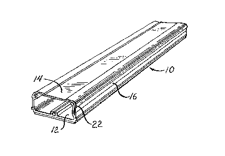
Figure 1 is a perspective view of the present one-piece duct system illustrating the
S cantilevered duct bias and supporting beam thereof;
Figure 2 is a front elevation view of the duc~ of Figure 1 illustrated in the closed
position;
Fig~re 3 is a ~ront elevation view of the duct of Figure 1 illustrated in the open
position;
lû Figure 4 is a front elevation view of a duct system not incorporating the suppor~ing
beam of the present invention and illustrating latch failure; and,
Figure S is a front eleva~ion view of the duct system of Figure 4 illustrating duct
co~ o.es~iQn.

2 ~ 7
D~s..;~ti~ll of the P~r~ d Embodiment
As best illustrated in Figures 1 - 3, the present one piece reclosable duct system 10
co,l~ es a wire cc?nt~inment chamlel 12 interconnf cted to a mating channel cover 14
S through an integral elnn~ d ~exible hinge 16. The hinge bridges respective ch~nnel
and cover first edges 18 and 20 and serves both to retain cover 14 in proper orientation
on, and ~ljac~nt to, channel 12 as well as facilitating the pivotal rotation of the cover
between channel closed (Figure 2) and channel open (Figure 3) conditions. The cover
is further m~int~ined in proper orientation by the cantilever suppordng beam ~ dis-
cussed in more detail below.
A double-sided tape or other adhesive 24 may advantageously be afffxed to the
bottom portion 26 of channel 12 to permit effor~less and subst~nti~lly ~ neous
mounting of the duct system along, for example, a wall or flooring.
The present one-piece duct system is fabricated as an integral uni~,r employing a
dual-durometer plastics co-extrusion process. More specifically, a cross-head de~lice is
employed to lirlk a pair of extruders ~o a single die. Olle of the extruders supplies the
relatively higher durometer PVC plastic ~hat forms the correspondingly more rig~d chan-
nel 12 tinrlu~ling ~ul~po ling beam 22~ and cover 14 members of the duct system while
the second extruder provides a lower durometer PVC material that de~mes the fle~ible
hinge 16.
With speci~lc reference to Figures 2 and 3, the previously lloted cantilever suppor$-
ing beam 22 is shown eyten(1in~ upwardly from one of the channel sidewalls 28. A gener-
ally U-shaped latch memher 30 is formed along the upper ed~e of the other sidewall 32
and inr~ es a recess 34 adapted to lockingly receive a mating hook 36. Hook 36 is
inte~rally extruded as part of the channel cover 14 and extends inwardly iErom ~he distal
edge of t~e cover (distal lbeing de~ined in rela~ionship to the hinge ed~e of cover 14~.
~igure 2 illustrates the duct in a proper closed and latched con~itio~ with hoolc 36 seated
in re~ss 34.

Figures 4 and 5 illustrate separate distortion modes that have been found to occur
in the absence of the cantilever support beam of the present in~entioll. In each case, the
low-durometer material that forms the flexible hinge 16 is shown deformed. Such de~or-
mation may result from inadvertent physical engagement with the duc~ as not-llnrommon-
S ly occurs during ordinary occur~n~y of the home, o~fice or other installed e,lviro~ ent.
Figure 4 depicts duct system distortion occ~s;on~d through the application of
lateral l~res~u.t applied, as illustrated by arrow 38, against the duct charmel cover 14.
This ~res~ure precipitates lateral flexure of the hinge and a correspot-~ling movement of
the cover which as shown may cause the unl~trhin~ and opening OI the duct system, in
turn, the exposure and possible escape of wiring therein. In Figure 5, a dowllw~ force
(arrow 40) may collapse the duct potentially resulting in duct unI~trl~in~, damage to
interior cables and cable retention clips and, in any eYent, causing a visually tlicple~sin~
perspectlve particularly in the vicinity of inter-duct connector elements which are them-
selves fabricated of a single ~lurorlleter rigid PVC plastic and therefore not subject to
collt;s~ondillg de~u~ lions.
As previously noted, it ;s against these dele~erious effects ~ ci~ted with umrhed-
uled hinge flexure ~hat the ~u~olLil~g beam ~ finds particular application. In ~his
regard, it should be rccc,~ ed that tbe flexible hinge material canno~ simply be removed
to oYescollle such adverse properties in view of the underlying desi~n obiective that the
one-piece duct system with.ct~n-l mllltiple duct access clJcles. In shor~ such m:lteri~l
slIbstit~tiQn; while o~viating the above~noted duct distortion problems9 merely replaces
one set of adverse featurcs with another.
Figure 2 best illustrates the pertinent structural details of the supporting beam 2~.
Importantly, by reason of its extrusion from thç relatively higher dulollle~er PVC material
and its cantilever confi~Iration, the upper region 42 of ~he beam m~y be urged laterally
and9 when so flexed~ produces a co.l~,~ol1ding counter-bias against the f~ex-causin$
object. More specifically, beam 22 is preferalbly extruded su~h ~hat its un~iased9 quies-
ceng ori~-nt~tiQn (FigurG 2) define~ an inte~r~nc~ r~l~t,~n~ w~th ~hg ~h~ l Go~3r

~7~ ~7
14 when the cover is in ~he closed position. I~us, as the cover is moved from it~s open
to slosed positions ~ie. from the position of Figure 3 to that of Figure 2), the cover
engages beam 22 correspondingly forcing it to the left. ~3eam 22 therefore pro~ides a
counter, rightward bias against the channel cover 14 thereby precluding or minimi7in~ the
S possibility of the llnl~tchin~ deformation shown in Figure 4.
Further, beam 22 is preferably dimensioned to engage the inside surface of the
ch~nnel cover at 44 when the duct system is in its closed condition (Figure 2). Beam 22
thereby serves as additional support for the cover, specifically, resis~ing any downward
force on the cover in the region adjacent hinge 16, in turn, greatly increasing the force
necess~ly to effect objectionable duct system deformation.
Itwill be appreciated from the ab~ve description that the present invention defines
an efficacious one-piece duct system permitting subst~nt~ y l~nlim~ted duct access cycles,
but without the deleterious effects of visual channel deformation or duct unl~tching.

Representative Drawing
A single figure which represents the drawing illustrating the invention.
Administrative Status

2024-08-01:As part of the Next Generation Patents (NGP) transition, the Canadian Patents Database (CPD) now contains a more detailed Event History, which replicates the Event Log of our new back-office solution.

Please note that "Inactive:" events refers to events no longer in use in our new back-office solution.

For a clearer understanding of the status of the application/patent presented on this page, the site Disclaimer , as well as the definitions for Patent , Event History , Maintenance Fee  and Payment History  should be consulted.

Event History

Description Date
Time Limit for Reversal Expired 2002-07-17
Letter Sent 2001-07-17
Grant by Issuance 1999-01-26
Inactive: Received pages at allowance 1998-08-13
Pre-grant 1998-08-13
Inactive: Final fee received 1998-08-13
Notice of Allowance is Issued 1998-02-20
Letter Sent 1998-02-20
Notice of Allowance is Issued 1998-02-20
Inactive: Application prosecuted on TS as of Log entry date 1998-02-17
Inactive: Status info is complete as of Log entry date 1998-02-17
Inactive: IPC assigned 1998-01-27
Inactive: IPC removed 1998-01-27
Inactive: First IPC assigned 1998-01-27
Inactive: Approved for allowance (AFA) 1998-01-27
Inactive: Delete abandonment 1997-10-02
Deemed Abandoned - Failure to Respond to Maintenance Fee Notice 1997-07-17
Inactive: Office letter 1997-07-17
All Requirements for Examination Determined Compliant 1994-05-29
Request for Examination Requirements Determined Compliant 1994-05-29
Application Published (Open to Public Inspection) 1993-01-25

Abandonment History

Abandonment Date Reason Reinstatement Date
1997-07-17

Maintenance Fee

The last payment was received on 1998-07-17

Note : If the full payment has not been received on or before the date indicated, a further fee may be required which may be one of the following

  • the reinstatement fee;
  • the late payment fee; or
  • additional fee to reverse deemed expiry.

Patent fees are adjusted on the 1st of January every year. The amounts above are the current amounts if received by December 31 of the current year.
Please refer to the CIPO Patent Fees web page to see all current fee amounts.

Fee History

Fee Type Anniversary Year Due Date Paid Date
MF (application, 5th anniv.) - standard 05 1997-07-17 1997-07-10
MF (application, 6th anniv.) - standard 06 1998-07-17 1998-07-17
Final fee - standard 1998-08-13
MF (patent, 7th anniv.) - standard 1999-07-19 1999-06-11
MF (patent, 8th anniv.) - standard 2000-07-17 2000-07-11
Owners on Record

Note: Records showing the ownership history in alphabetical order.

Current Owners on Record
DEK, INC.
Past Owners on Record
DONALD G. SANTUCCI
MARK N. COHEN
MARK PAGE
Past Owners that do not appear in the "Owners on Record" listing will appear in other documentation within the application.
Documents

To view selected files, please enter reCAPTCHA code :


To view images, click a link in the Document Description column. To download the documents, select one or more checkboxes in the first column and then click the "Download Selected in PDF format (Zip Archive)" or the "Download Selected as Single PDF" button.

List of published and non-published patent-specific documents on the CPD .

If you have any difficulty accessing content, you can call the Client Service Centre at 1-866-997-1936 or send them an e-mail at CIPO Client Service Centre.


Document
Description 
Date
(yyyy-mm-dd) 
Number of pages   Size of Image (KB) 
Claims 1997-12-22 4 142
Description 1998-08-12 8 315
Description 1993-11-04 7 319
Claims 1993-11-04 3 95
Abstract 1993-11-04 1 21
Drawings 1993-11-04 1 39
Representative drawing 1998-10-18 1 15
Representative drawing 1999-01-20 1 13
Commissioner's Notice - Application Found Allowable 1998-02-19 1 165
Maintenance Fee Notice 2001-08-13 1 179
Correspondence 1998-02-19 1 100
Correspondence 1998-08-12 3 93
Fees 1998-07-16 1 31
Fees 2000-07-10 1 30
Fees 1996-07-01 1 34
Fees 1995-07-12 1 33
Fees 1994-06-28 1 32
Courtesy - Office Letter 1992-10-22 1 76
Courtesy - Office Letter 1994-06-23 1 38
Prosecution correspondence 1997-10-05 4 118
Examiner Requisition 1997-04-03 2 73
Prosecution correspondence 1994-04-28 1 37
Prosecution correspondence 1995-12-10 4 142