Language selection

Search

Patent 2074307 Summary

Third-party information liability

Some of the information on this Web page has been provided by external sources. The Government of Canada is not responsible for the accuracy, reliability or currency of the information supplied by external sources. Users wishing to rely upon this information should consult directly with the source of the information. Content provided by external sources is not subject to official languages, privacy and accessibility requirements.

Claims and Abstract availability

Any discrepancies in the text and image of the Claims and Abstract are due to differing posting times. Text of the Claims and Abstract are posted:

  • At the time the application is open to public inspection;
  • At the time of issue of the patent (grant).
(12) Patent: (11) CA 2074307
(54) English Title: ROPE GUIDE
(54) French Title: GUIDE DE CABLE
Status: Expired and beyond the Period of Reversal
Bibliographic Data
(51) International Patent Classification (IPC):
  • B66D 1/38 (2006.01)
  • B66D 1/36 (2006.01)
(72) Inventors :
  • SELL, LESLIE J. (United States of America)
(73) Owners :
  • INGERSOLL-RAND COMPANY
(71) Applicants :
  • INGERSOLL-RAND COMPANY (United States of America)
(74) Agent: NORTON ROSE FULBRIGHT CANADA LLP/S.E.N.C.R.L., S.R.L.
(74) Associate agent:
(45) Issued: 1995-12-12
(22) Filed Date: 1992-07-21
(41) Open to Public Inspection: 1993-01-30
Examination requested: 1992-07-21
Availability of licence: N/A
Dedicated to the Public: N/A
(25) Language of filing: English

Patent Cooperation Treaty (PCT): No

(30) Application Priority Data:
Application No. Country/Territory Date
07/737,313 (United States of America) 1991-07-29

Abstracts

English Abstract


A rope hoist rope guide is disclosed which is
readily mounted on a drum by a unique split ring
construction and includes unique rollers which
cooperate with the grooves in the drum to position
the guide ring and accurately deploy the rope to
appropriately lay the rope in the drum grooves
regardless of side forces applied.


Claims

Note: Claims are shown in the official language in which they were submitted.

The embodiments of the invention in which an
exclusive property or privilege is claimed are defined as
follows:
1. A rope guide for guiding rope on a spiral grooved
cylindrical drum rotating on its axis comprising:
a guide mounting means encircling at least a portion
of the drum in cooperation with the drum groove for mounting a
rope guide means;
a plurality of groove cooperating means on said
guide mounting means for rotatably securing said guide means
to said drum and for tracking said guide mounting means in
spiral advance along said drum in response to rotation of said
drum;
said rope guide means being in tangential alignment
with said guide mounting means and said drum for maintaining
rope played on said drum in tangential intersection with the
circumference of said drum and alignment perpendicular to said
axis of said drum;
said guide mounting means further comprising a
resilient split ring encircling said drum in rolling contact
with a drum groove, said split ring permitting radial
expansion of said split ring in response to an unaligned rope
causing said split ring to roll out of a drum groove;
means mounted on said guide mounting means for
sensing the radial expansion of said split ring;
said split ring being further comprised of two half
rings joined at one end by a hinge and resiliently fastened
together at its other end by a resilient fastening means; and
said resilient fastening means further comprises a
means for sensing separation of said split ring.
2. A rope guide according to claim 1, wherein said
resilient fastening means further comprises a spring loaded
bolt which permits limited separation of said two half rings
in response to radial outward loading of said guide mounting
means.
- 9 -

3. A rope guide according to claim 1, wherein said
means for sensing separation comprises a sensing valve for
sensing the condition of separation resulting from an
unaligned load condition and providing a signal means for
control of said drum operation.
4. A rope guide according to claim 1, wherein said
means for sensing separation initiates a signal which in turn
prevents further operation of said drum in the progressing
direction of operation while allowing reverse operation to
correct the unaligned load condition.
5. A rope guide according to claim 1, wherein said
groove cooperating means further comprises a plurality of
rollers spaced about the circumferential interior of said
guide mounting means having longitudinal offset in their
location corresponding to the groove pitch of the drum groove
whereby said guide mounting means maintains an orientation in
a plane perpendicular to the longitudinal axis of the groove
drum and is traversed axially along the drum in a direction
determined by the direction of rotation of the drum.
6. A rope guide according to claim 5, wherein said
rollers are mounted in a pocket on said guide means by means
of a shaft pin and positioned within said pocket by spacers
having a thickness which is equal to the pitch of the drum
groove divided by the number of rollers whereby the
positioning of the rollers may be set to the drum pitch by
positioning of said spacers on said shaft pin to one side or
the other of said roller.
7. A rope guide according to claim 1, wherein said
guide mounting means is provided with reaction roller means to
prevent rotation of said guide mounting means about the drum.
- 10 -

8. A rope guide according to claim 1, wherein said rope
guide means is attached to said guide mounting means in
substantially tangential relationship to said guide mounting
means and said drum circumference in normal operation.
9. A rope guide means according to claim 8, wherein
said rope guide means permits limited radial swing of said
rope guide means and limits axial swing whereby forces created
by a side pull acting to produce axial swing on the rope guide
means are transmitted to said guide mounting means causing
said guide mounting means to ride out of the drum groove by a
drum groove side camming action and thereby further causing a
radial outward face on said guide mounting means.
- 11 -

Description

Note: Descriptions are shown in the official language in which they were submitted.


2074307
ROPE GUIDE
BACKGROUND OF THE INVENTION
This invention relates generally to rope guides
for hoists and the like and more particularly to
wire rope hoists having grooved drums. This does
not exclude the possible use on other winding
05 machinery that uses rope.
In a typical wire rope hoist installation the
hoist assembly, consisting of a winding drum and a
means for driving the drum, is mounted in a frame
that is suspended on guide wheels which run on the
flanges of an 'I' beam. A standard crane hook that
hangs on the wire rope below the hoist is the usual
means provided for lifting loads.
The hoist is suspended above the work area at
heights that often approach and sometimes exceed 100
feet.
Various methods of reeving the hoist to obtain
the desired lift capacity and hook travel are
employed, the simplest method being 'single reeving'
at standard load capacity where the hook moves from
~'
.- , . .

2074307
-
end to end of the hoist drum when raising or
lowering a load. Another method called 'double
- reeving' employs a right and left hand grooved hoist
drum with the rope attached to one side then looped
05 through a pulley assembly on the hook and attached
to the opposite side of the drum. With this method
the hook remains in line with the center of the drum
throughout its operating height. In addition to
these methods of reeving the hoist may also be multi
part reeved to increase lifting capacity.
To reduce wear on the rope it is usual to have
only one layer on the hoist drum and when multi part
lines are used the drum length is increased
considerably especially at greater operating
heights. When the hoist is suspended parallel to
the beam it is often not possible to operate the
hoist near a wall or the end of the beam due to the
length of drum. For this reason the hoist is
sometimes suspended across the beam since its width
is considerably less than its length. In this case
it is necessary to 'double reeve' the hoist so that
load is always on the center of the beam.
Wire rope hoists are designed for vertical

207~7
lifting only but often the operator will pull
sideways to reach a load that is not under the
hoist. This can cause the rope to jump the drum
grooving causing damage to the rope and imbalance on
05 the hoist particularly when it is suspended across
the beam.
The foregoing illustrates limitations known to
exist in present rope hoists. Thus, it is apparent
that it would be advantageous to provide an
alternative directed to overcoming one or more of
the limitations set forth above. Accordingly, a
suitable alternative is provided including features
more fully disclosed hereinafter.
SUMMARY OF THE INVENTION
In one aspect of the present invention this is
accomplished by apparatus for guiding rope on a
spiral grooved drum comprising a guide mounting
means encircling at least a portion of the drum in
cooperation with the drum groove for mounting a rope
guide means; a plurality of groove cooperating means
on said guide mounting means for rotatably securing
said guide means to said drum and for tracking said
guide mounting means in spiral advance along said

2074307
drum in response to rotation of said drum; and said rope guide
means being in tangential alignment with said guide mounting
means and said drum for maintaining rope played on said drum
in tangential alignment perpendicular to said drum.
According to a still further broad aspect of the
present invention there is provided a rope guide for guiding
rope on a spiral grooved cylindrical drum rotating on its
axis. A guide mounting means encircles at least a portion of
the drum in cooperation with the drum groove for mounting a
rope guide means. A plurality of groove cooperating means are
provided on the guide mounting means for rotatably securing
the guide means to the drum and for tracking the guide
mounting means in spiral advance along the drum in response to
rotation of the drum. The rope guide means is in tangential
alignment with the guide mounting means and the drum for
maintaining rope played on the drum in tangential intersection
with the circumference of the drum and alignment perpendicular
to the axis of the drum. The guide mounting means further
comprises a resilient split ring encircling the drum in
rolling contact with a drum groove. The split ring permits
radial expansion of the split ring in response to an unaligned
rope causing the split ring to roll out of a drum groove.
Means is mounted on the guide mounting means to sense the
radial expansion of the split ring. The split ring is further
comprised of two half rings joined at one end by a hinge and
resiliently fastened together at its other end by a resilient
fastening means. The resilient fastening means further
comprises a means for sensing separation of the split ring.
The foregoing and other aspects will become apparent
from the following detailed description of the invention when
considered in conjunction with the accompanying drawing
~igures .
Fig. 1 is a section side elevation view illustrating
an embodiment of the rope guide according to the present
invention cooperating with a grooved drum in a hoist.
. ~ - 4 -

2074307
_
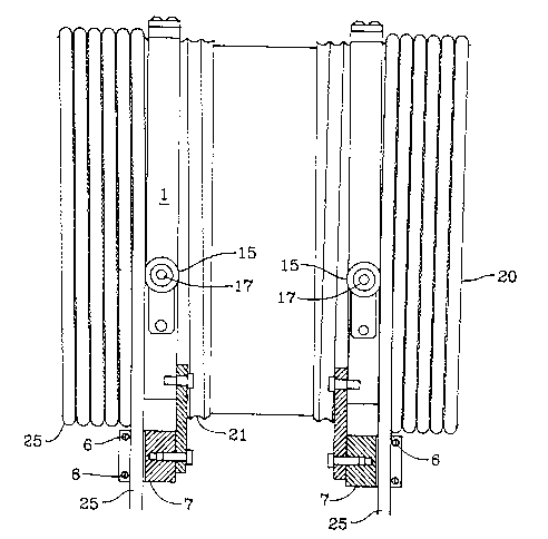
Fig. 2 is a side elevation showing the rope guide
according to the present invention cooperating with a grooved
rope drum.
Fig. 3 is a cross-section of the detail of the
grooved roller for the present invention.
`~`:
- 4a -

2~743Q7
._
DETAILED DESCRIPTION
Referring to Fig. 1, the guide mounting means 1
consists of a split steel ring joined at the top by
a steel hinge 2 and held together at the bottom by a
spring 3 and bolt 4. A key 5 maintains alignment
05 between the ring halves. The guide mounting means 1
is mounted for rotation on a hoist drum 20 which is
in turn mounted in driven rotation in a hoist frame
22. The hoist frame 22 in turn may be mounted on a
track (not shown) with track or trolley wheels 23 to
allow positioning of the hoist over the load.
The wire rope is guided by cotter pins 6 in
retainer block 7 that is loosely pivoted from one
ring half by arm 8. This allows the rope to move in
any direction except sideways.
Four steel groove rollers 9 are housed in
identical pockets 10 (two in each half ring) and are
free to turn on pins 11 that are pressed through the
ring. Each roller is positioned in its pocket by
spacers 12. The spacers are all the same thickness
which is equal to the pitch of the drum grooving
divided by the number of rollers. The groove

207~307
rollers 9 ride in the hoist drum grooves 21 and
cooperate with the groove to align or track the
guide and move it along the drum 20 as the drum 20
rotates.
05 The ring is timed on the drum grooving so the
rope 25 is close to the ring at the point that it
enters retainer 7. Selecting the pocket nearest to
the advance of the drum grooving allows all the
spacers to be positioned on one side of a roller
(see Fig. 3). Calling this roller #l and following
advance of the drum groove then roller #2 would be
positioned with one spacer on the left and two on
the right, roller #3 - two spacers on the left and
one on the right, roller #4 - all spacers on the
left. For opposite hand grooving #l roller would be
positioned in mirror image to Fig. 3 and the spacer
sequence would be similar following the advance of
the drum groove.
The 'double reeve' balance pulley 26 is
suspended from the hoist frame 22 and its position
is shown for reference.
Sensing valve 13 located at the bottom of the
ring is set by adjusting screw 14.

207~307
-
Reaction rollers 15 are mounted on the side of
the ring through adapter 16 and screw 17.
Referring to Fig. 2, a cross sectional view of
the ring installed on the hoist drum 20 is shown
05 together with a side view showing a typical
installation for double reeving using identical
components assembled for right and left hand
grooving.
Reaction rollers 15 are set to loosely contact
the hoist body rails 18 to prevent rotation of the
ring and thereby cause the ring to travel with the
rope along the hoist drum as it rotates to raise or
lower a load.
If the travel of the ring along the hoist drum
is impeded by resistance from a side pull acting on
the retainer 7 and arm 8 or resistance from some
other cause acting at some other point on the ring,
the groove rollers 15 will start to cam out of the
drum groove causing a radial outward load that
eventually overcomes spring 3 and opens the ring
slightly at the bottom. This in turn actuates
sensing valve 13.
., ~

2074307
Sensing valve 13 is connected to a pneumatic
circuit the logic of which prevents further
operation of the hoist in that direction but allows
operation in the opposite direction to remove the
05 overload. When two rings are used for double reeved
hoists either one may sense and send an overload
signal.

Representative Drawing
A single figure which represents the drawing illustrating the invention.
Administrative Status

2024-08-01:As part of the Next Generation Patents (NGP) transition, the Canadian Patents Database (CPD) now contains a more detailed Event History, which replicates the Event Log of our new back-office solution.

Please note that "Inactive:" events refers to events no longer in use in our new back-office solution.

For a clearer understanding of the status of the application/patent presented on this page, the site Disclaimer , as well as the definitions for Patent , Event History , Maintenance Fee  and Payment History  should be consulted.

Event History

Description Date
Inactive: IPC from MCD 2006-03-11
Time Limit for Reversal Expired 2005-07-21
Letter Sent 2004-07-21
Inactive: Late MF processed 2002-01-03
Letter Sent 2001-07-23
Grant by Issuance 1995-12-12
Application Published (Open to Public Inspection) 1993-01-30
All Requirements for Examination Determined Compliant 1992-07-21
Request for Examination Requirements Determined Compliant 1992-07-21

Abandonment History

There is no abandonment history.

Fee History

Fee Type Anniversary Year Due Date Paid Date
MF (patent, 5th anniv.) - standard 1997-07-21 1997-07-02
MF (patent, 6th anniv.) - standard 1998-07-21 1998-07-02
MF (patent, 7th anniv.) - standard 1999-07-21 1999-07-02
MF (patent, 8th anniv.) - standard 2000-07-21 2000-07-04
Reversal of deemed expiry 2001-07-23 2002-01-03
MF (patent, 9th anniv.) - standard 2001-07-23 2002-01-03
MF (patent, 10th anniv.) - standard 2002-07-22 2002-07-03
MF (patent, 11th anniv.) - standard 2003-07-21 2003-07-03
Owners on Record

Note: Records showing the ownership history in alphabetical order.

Current Owners on Record
INGERSOLL-RAND COMPANY
Past Owners on Record
LESLIE J. SELL
Past Owners that do not appear in the "Owners on Record" listing will appear in other documentation within the application.
Documents

To view selected files, please enter reCAPTCHA code :


To view images, click a link in the Document Description column. To download the documents, select one or more checkboxes in the first column and then click the "Download Selected in PDF format (Zip Archive)" or the "Download Selected as Single PDF" button.

List of published and non-published patent-specific documents on the CPD .

If you have any difficulty accessing content, you can call the Client Service Centre at 1-866-997-1936 or send them an e-mail at CIPO Client Service Centre.


Document
Description 
Date
(yyyy-mm-dd) 
Number of pages   Size of Image (KB) 
Cover Page 1993-11-27 1 13
Abstract 1993-11-27 1 11
Claims 1993-11-27 5 128
Description 1993-11-27 8 187
Drawings 1993-11-27 2 62
Abstract 1995-12-12 1 13
Description 1995-12-12 9 244
Cover Page 1995-12-12 1 15
Claims 1995-12-12 3 108
Drawings 1995-12-12 2 64
Representative drawing 1999-03-11 1 24
Maintenance Fee Notice 2001-08-20 1 179
Late Payment Acknowledgement 2002-01-24 1 172
Maintenance Fee Notice 2004-09-15 1 173
Fees 1996-06-18 1 43
Fees 1995-06-29 1 57
Fees 1994-07-04 1 62
PCT Correspondence 1995-10-02 1 37
Courtesy - Office Letter 1992-07-21 1 42
Prosecution correspondence 1995-03-15 2 53
Examiner Requisition 1994-09-27 1 55