Language selection

Search

Patent 2074587 Summary

Third-party information liability

Some of the information on this Web page has been provided by external sources. The Government of Canada is not responsible for the accuracy, reliability or currency of the information supplied by external sources. Users wishing to rely upon this information should consult directly with the source of the information. Content provided by external sources is not subject to official languages, privacy and accessibility requirements.

Claims and Abstract availability

Any discrepancies in the text and image of the Claims and Abstract are due to differing posting times. Text of the Claims and Abstract are posted:

  • At the time the application is open to public inspection;
  • At the time of issue of the patent (grant).
(12) Patent: (11) CA 2074587
(54) English Title: FRONT WHEEL BRAKE FOR TANDEM WHEELED ROLLER SKATE
(54) French Title: FREINS AVANT POUR PATINS A ROULETTES EN TANDEM
Status: Expired and beyond the Period of Reversal
Bibliographic Data
Abstracts

English Abstract


A roller skate with a plurality of skate rollers
including a front roller has a front end brake comprising a
brake wheel forwardly of the front roller with a braking
member between the brake wheel and the front roller. The
brake wheel has a lower reach above that of the front
roller when the skate is in the rolling position on the
rollers and the brake wheel in a brake released position.
The brake wheel is movable rearwardly so that its periphery
is against the brake member in a braking position when the
skate is tipped forwardly away from the rolling position
onto the brake wheel. A spring is provided which moves the
brake wheel back to the brake released position when the
skate is returned to the rolling position.


French Abstract

Patin à roulette comprenant une série de roues, y compris une roue avant munie d'un frein avant constitué d'une roue de freinage située devant la roue avant et d'un dispositif de freinage placé entre la roue de freinage et la roue avant. La roue de freinage n'a pas la même portée que la roue avant étant donné qu'elle se situe au-dessus de cette dernière lorsque le patin est en position de roulement et repose sur toutes ses roues et que la roue de freinage est en position de repos. La roue de freinage peut se déplacer vers l'arrière, de sorte qu'en position de freinage, lorsque le patin est incliné vers l'avant, hors de sa position de roulement, et s'appuie sur la roue de freinage, cette dernière se déplace vers l'arrière afin d'entrer en contact avec le dispositif de freinage. La présente invention prévoit un ressort pour remettre la roue de freinage en position de repos une fois que le patin est de nouveau en position de roulement.

Claims

Note: Claims are shown in the official language in which they were submitted.

- 6 -
THE EMBODIMENTS OF THE INVENTION IN WHICH AN EXCLUSIVE
PROPERTY OR PRIVILEGE IS CLAIMED ARE DEFINED AS FOLLOWS:
1. A roller skate with a front end brake on said skate, said skate
having a skate boot with a boot undersurface and a rigid frame secured to
said undersurface, a plurality of rollers comprising a front roller and other
rollers behind and inline with said front roller, all of said rollers being
rotatably mounted on roller axles secured to said rigid frame, said brake
comprising a brake wheel rotatably mounted on a brake wheel mount
which is movably secured to said boot undersurface forwardly of said front
roller, a brake member secured to said boot undersurface between and
spaced from said brake wheel and said front roller, said skate being
movable between a rolling position in which all of said rollers roll along a
rolling surface on which said skate is supported to a braking position in
which said skate is tipped forwardly from said rolling position onto said
brake wheel, said brake wheel having a peripheral surface with a lower
reach above that of said front roller and being freely rotatable and free of
the rolling surface when said skate is in the rolling position and when said
skate is in the braking position, said brake wheel is pushed rearwardly
such that said peripheral surface of said brake wheel is moved onto and
binds against rotation on said brake member; and a spring mounted on a
spring support to said boot undersurface, said spring pushing on said brake
wheel mount in a direction away from said front roller and biasing said
brake wheel away from said front roller when said skate is in the rolling
position.
2. A skate as claimed in Claim 1 wherein said brake wheel is
smaller than said front roller.
3. A skate as claimed in Claim 1, wherein said brake wheel
mount comprises a bracket pivotally secured to said boot undersurface.
4. A skate as claimed in Claim 1, wherein said brake member is
movably mounted on said boot undersurface and wherein said brake
wheel when in the braking position pushes said brake member onto said
front roller.

- 7 -
5. A skate as claimed in Claim 4, wherein said brake member
has a forward arcuate surface facing said brake wheel and a rearward
arcuate surface facing said front roller.
6. A skate as claimed in Claim 1, including a second wheel
rotatably held in said brake wheel mount above and forwardly of said
brake wheel.
7. A skate as claimed in Claim 1, wherein said front end brake is
located in a position directly beneath said skate boot.

Description

Note: Descriptions are shown in the official language in which they were submitted.


SJ-8970US - 1 - ~ 8 7
TITT,T~ FRONT WHF.T~'.T, BRAKE FOR ROT,T,ER SKATE
FIELD OF THE INVENTION
The present invention relates to a roller skate
with a front mounted brake.
BACKGROUND OF THE INVENTION
Prior art methods of braking the forward motion of
old style roller skates use a friction pad fixed forwardly
and downwardly to the front of the boot which allows the
operator to slow forward motion or to stop by merely
raising the heel of the boot causing the friction pad to
contact the road surface.
More recently, skates referred to as in-line skates
which generally can be operated with greater dexterity than
the older roller type skates have rearwardly mounted
friction pads which are operated by raising the toe of the
boot to thereby stop the motion from the rear. The
disadvantage encountered in this motion is the tendency of
the operator to over-balance and fall backwards which can
result in serious back and head injury.
A recent development in the braking for roller
skates is disclosed in United States Patent 5, 088,748 where
a brake wheel is provided behind the in-line roller wheels
and is operated by the lifting of the boot front. This
puts the extra brake wheel into contact with the road
surface biasing a pivotal connection between linkage bars
attached to the skate boot and roller wheel bracket where
lifting action controlled by the skate operator actuates
the brake on the extra wheel. Once again, the operator
must lean backwards to a dangerous position in order to
operate the brake of this patented construction.

SJ-8970US - 2 - ~ ~ 7 ~ ~ 8 7
SU~M~RY OF T~F. INVENTION
The present invention provides a roller skate with
a front as opposed to a rear operated brake so that when
the skate is moved to the braking position, the operator
does not have to lean rearwardly to a dangerous position on
the skate.
More particularly, the skate with brake of the
present invention comprises a plurality of rollers
including a front roller beneath a skate boot. Provided
forwardly of the front roller is a front brake wheel which
is elevated from the ground in a brake released position
when the skate is rolling on the rollers. A brake member
is disposed between the front wheel and the front roller
and the front wheel is movable rearwardly so that the
periphery of the front wheel is against the brake member to
provide a braking action on the skate when the operator
raises the heel as opposed to the toe of the skate. A
spring is also provided in the brake and when the operator
lowers his or her heel so that the skate once again assumes
its normal rolling position, the front wheel is moved by
the spring to the brake released position away from the
brake member.
BRIF.F DF~CRIPT~ON OF T~F. DRAWINGS
The above as well as other advantages and features
of the present invention will be described in greater
detail according to the preferred embodiments of the
present invention in which ;
Figure 1 is a perspective view of a roller skate
with a front mounted brake according to a preferred
embodiment of the present invention;
Figure 2 is an enlarged view of the front brake
area from the skate of Figure 1 with the brake in its
released position;

8 ~
SJ-8970US - 3 -
Figure 3 is a view similar to Figure 2 with the
brake to the engaged position;
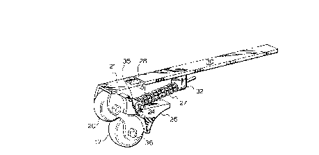
Figure 4 is a perspective view of the actual brake
assembly removed from the skate of Figure 1.
DF.TAILED DESCRIPTION ACCORDING TO THE PREFERRED
FMRODIMENTS OF THE PRESF.NT TNVF.NTION
A roller skate is provided in which in-line running
rollers collectively designated at 10 are arranged in
single file centrally of a skate generally indicated at 12.
A boot 13 consisting of a sole plate 14 has a front end 16
and a heel portion 18.
The skate consists of a platform comprising the
sole plate 14 with a pair of parallel spaced apart wheel
support plates 22 along the horizontal axis of the skate
between the front 16 and the rear 18 of the sole plate 14.
Axle shafts 38 extend between adjacent support plates 22 to
provide rotatable mounts for the rollers 10 which rotate
freely when the skate is rolling along a rolling surface
for the skate. Two wheels 17 and 20 smaller than the
rollers are positioned at the front of the skate. The
lower reaches of these two wheels are elevated relative to
the lower reach of the front roller and are free of the
running surface 40 when the skate is operated in the normal
fashion with all rollers 10 in contact with the road
surface 40. The two small wheels 17 and 20 are mounted on
axles 36,33 journalled in a U-shaped bracket 21 which is
pivotally fitted at 28 to a spring support 30 fixed to sole
plate 14. The pivotal mounting of bracket 21 ensures that
this bracket carrying wheels 17 and 20 will move rearwardly
when the skate is tipped forwardly and wheel 17 is pushed
downwardly onto the running surface 40.
A wedge shaped brake member 24 is located between
the brake wheel 17 and the front roller 10. This brake

SJ-8970US - 4 ~ 8 7
member has a forward rounded brake surface 25 and a
rearward rounded brake surface 26. The brake member is
pivotally mounted to the bracket 21 above the brake
surfaces with a spring 27 trapped between the upper end of
the brake member above its pivot point and a spring stop 32
on the base of the spring support 30. A further smaller
clip like spring 35 is also mounted on the brake member 24
and normally urges the upper part of the brake member
against wheel 20 and the lower part of the brake member off
of wheel 17 when the skate is in its normal rolling
position. As will be seen in Figure 2 of the drawings,
wheel 17 when it is not in the braking position is freely
rotatable.
When the skate is tipped forwardly onto brake wheel
17 as shown in Figure 3 of the drawings, bracket 21
carrying the brake wheel is pivoted rearwardly against the
pressure of spring 27 so that the surface of the brake
wheel engages the forward arcuate surface 25 of brake
member 24. This provides a frictional braking of wheel 17.
The brake wheel 17 in turn applies a rearward pressure on
the brake member 24 such that the brake member 24 is then
pushed rearwardly to the point where its rearward arcuate
braking surface 26 engages the periphery of front roller 10
further adding to the braking action on the skate. Figure
3 also shows that the force applied by wheel 17 on the
brake member 24 causes the upper end of the brake member 24
to pull away from wheel 20. This wheel 20 becomes freely
rotatable and provides a safety wheel if the skate is
tipped too abruptly because the operator, rather than
pitching forwardly will have his or her weight applied to
the now free wheeling safety wheel 20. In fact, the
operator can rock the skate when it is tipped forwardly
between the wheels 20 and 17 which starts to release from
the braking position when the weight of the skater is on
wheel 20 which allows the operator to slow down the rolling
, .~

2 Q ~ ~ 5 ~ 7
SJ-8970US - 5 -
action and finally stop the skate gradually rather than
coming to an abrupt stop.
As soon as the skate is moved back to its normal
rolling position, spring 27 pushes bracket 21 about its
pivot 28 so that the bracket carries the two wheels 17 and
20 forwardly such that wheel 17 releases from the front of
the brake member 24. Spring 35 then pushes the upper part
of the brake member 24 back onto the most forward wheel 20
which pivots the lower part of the brake member 24 off of
the brake wheel 17.
The spring action of the brake also allows it to be
rocked between the brake wheel 17 and the front roller 10
to once again gradually control the braking action on the
skate.
Although various preferred embodiments of the
present invention have been described herein in detail, it
will be appreciated by those skilled in the art, that
variations may be made thereto without departing from the
spirit of the invention or the scope of the appended
claims.

Representative Drawing
A single figure which represents the drawing illustrating the invention.
Administrative Status

2024-08-01:As part of the Next Generation Patents (NGP) transition, the Canadian Patents Database (CPD) now contains a more detailed Event History, which replicates the Event Log of our new back-office solution.

Please note that "Inactive:" events refers to events no longer in use in our new back-office solution.

For a clearer understanding of the status of the application/patent presented on this page, the site Disclaimer , as well as the definitions for Patent , Event History , Maintenance Fee  and Payment History  should be consulted.

Event History

Description Date
Time Limit for Reversal Expired 2000-07-24
Letter Sent 1999-07-26
Grant by Issuance 1997-12-02
Inactive: Application prosecuted on TS as of Log entry date 1997-09-24
Inactive: Status info is complete as of Log entry date 1997-09-24
Pre-grant 1997-07-25
Notice of Allowance is Issued 1997-01-28
Application Published (Open to Public Inspection) 1994-01-25
All Requirements for Examination Determined Compliant 1993-12-13
Request for Examination Requirements Determined Compliant 1993-12-13

Abandonment History

There is no abandonment history.

Maintenance Fee

The last payment was received on 1997-07-22

Note : If the full payment has not been received on or before the date indicated, a further fee may be required which may be one of the following

  • the reinstatement fee;
  • the late payment fee; or
  • additional fee to reverse deemed expiry.

Patent fees are adjusted on the 1st of January every year. The amounts above are the current amounts if received by December 31 of the current year.
Please refer to the CIPO Patent Fees web page to see all current fee amounts.

Fee History

Fee Type Anniversary Year Due Date Paid Date
MF (application, 5th anniv.) - small 05 1997-07-24 1997-07-22
Final fee - small 1997-07-25
MF (patent, 6th anniv.) - small 1998-07-24 1998-07-21
Owners on Record

Note: Records showing the ownership history in alphabetical order.

Current Owners on Record
MARIO DE SANTIS
Past Owners on Record
None
Past Owners that do not appear in the "Owners on Record" listing will appear in other documentation within the application.
Documents

To view selected files, please enter reCAPTCHA code :


To view images, click a link in the Document Description column. To download the documents, select one or more checkboxes in the first column and then click the "Download Selected in PDF format (Zip Archive)" or the "Download Selected as Single PDF" button.

List of published and non-published patent-specific documents on the CPD .

If you have any difficulty accessing content, you can call the Client Service Centre at 1-866-997-1936 or send them an e-mail at CIPO Client Service Centre.


Document
Description 
Date
(yyyy-mm-dd) 
Number of pages   Size of Image (KB) 
Abstract 1997-01-27 1 21
Description 1997-01-27 5 206
Claims 1997-01-27 2 67
Drawings 1997-01-27 4 111
Description 1995-06-09 4 288
Drawings 1995-06-09 4 201
Claims 1995-06-09 2 119
Abstract 1995-06-09 1 64
Representative drawing 1997-11-24 1 9
Abstract 1998-08-26 1 21
Description 1998-08-26 5 206
Claims 1998-08-26 2 67
Maintenance Fee Notice 1999-08-22 1 179
Fees 1997-07-21 1 48
Fees 1996-06-11 1 39
Fees 1995-07-04 1 37
Fees 1994-11-14 1 44
Courtesy - Office Letter 1993-07-11 1 62
Courtesy - Office Letter 1993-07-11 1 64
Courtesy - Office Letter 1993-11-23 1 51
Courtesy - Office Letter 1993-12-12 1 57
Courtesy - Office Letter 1994-01-16 1 42
Courtesy - Office Letter 1994-03-07 1 63
PCT Correspondence 1997-07-24 1 42
PCT Correspondence 1994-02-10 2 59
PCT Correspondence 1993-07-04 1 13
Prosecution correspondence 1995-05-28 3 110
Prosecution correspondence 1993-11-18 2 65