Note: Descriptions are shown in the official language in which they were submitted.
207~91S
A ~THOD OF MANUFACTII~ING A COOKI~lG UTENSIL
SPECIFICA'rION
Thi~ application 1~ related to th~ con~urrently flle~
commonly assigned copending application Ser. No. 07/
(Atto~ney's docket No. 18~51) corresponding to Ger~an
appli~ation P ~ 25 115.6 ~iled 30 July 1992.
Field_of the ~nvention
The inven~ion relates to a ~ethod o~ manu~ac~urin~ a
coo~ing utensil and, more particularly, to a pres~ure-pul~e
method o~ ~abriaa~inq the utensil.
~ cookin~ utencil can comprise a round oontainer ~or
holdlng the food, the contai~er having a base, a plate ~ad~
of heat-aondu~ting mat-rial and a cap enclo~ln~ the plate,
the base of the enclosing ca~ b~ing g~en a convex
curvature towards the aontainer and the cap having a collar
whiah ab~ts t~e container in a curved transltion region
betwe~n the container base and ~he container ~acket.
The aontainer and the cap can be made of stainless
steel and the plate can be intermetalliaally ~onded to t~
container ~ase and ths aap.
l 207491~
In order to produce the intermetall~c bond a plate can
be inserted into the cap so as to leave an annular flo~
6pace between it and the prefo~med cap collar.
The ass~mbly comprising the container ba8~, the plate
and the cap oan be centered between the punch and the die
of a pres~ and intermetallically bonded by single or
multiple ~pulse pressure so as to form the curvex
curvature of the cap bottom and to mold the rim of the cap
around the aontainer. During the pulse pressure t~e plate
is pressed by plastic deformation into the flow space,
where it i8 ~ntermetalllcally bonded to the cap base, the
cap collar and the corresponding region of t~e container.
of course the method can be ~arried ou~ at amblent
temperature or with heating.
The pulse enerqy wlll be adjus~ed to the tempe~ature
of the contain-r, at least in ~he base region, th~ o~p and
the plat~ Usuall~ the~e t~mperatures are chosen so as to
be near but suffi~iently below the meltin~ pol~t of the
plate material.
AlUmlnum in the form of indust~ially pure alumln~m i8
a ~ery useful plat~ ~aterial. Coppex is also a useful
plats material.
2074915
The cooking utensils can be pots, pans or the llke,
more paxticularly ~ooking po~s and pressure cooker~.
The plate improves the heat trans~er fro~ a hotplate
or sto~e plate to the food. The heat tran~fer is adversely
aff~cted if ~he ~ntermetallia bond is damaged. Thi~
applies ~ven if the damage o~cur~ in the region oS the cap
collar.
of cour6e, the tool~, i.e. the die and the ra~, for
applylng pulse pressure in a press, must be ad~usted 80
a~ to obtain the aorementi~ne~ ~lightly convex shaping of
the cap bo~tom. Usually the contalner base ls made
slightly con~ex outwardly. ~he geometrical condition~ with
regard to the container ~ase, the cap and the plate ~ust be
ad~usted 80 that in the finished coo~ing utensil, the
plate completely fills ~he ~pace between the container ~ase
and th~ cap, i.e. ~nter- and fill0 tho flow ~pace wh~n the
intermetallic bond is manufa~tured~
A defined, undis~urbed flow of plate materlal i~
important for the ~ntermetallia bond. The plate aan be a
fla~ plate or can have a lQnticular or ~tepped
: aross-sea~ion.
o::
207~9~
It is particularly ~mportant also that the ri~ o~ the
cap collar should fau~tlessly abut the conta~ner. if plate
~aterlal ~lows out here, the containe~ will have to be
re~ected ~or aesthetic reasons and to a~oid corro~ion.
I~ there is a gap, water can enter during use or
washing and can cause trouble ~hxough corrosion.
In the known method, on which the invention i8 based
(EP 0 209 745), the operation is as follows : the plat~ 18
secured in the center of the cap surface by spot welding.
lO The assembly ~omprising the cap, pla~e and container base
or container is he~ted to a ~emperature which i~ near b~
below the melting point of the plate material. The lnit~a
thickness of the plate is a~ least 20~ greater than the
~inal thickness of the p~ate afte~ the intermetallic bond
has been formed.
In a flr6~ phasQ o~ pul5e p~es~ure, the pressure l~
applied progresslvely ~rom the center to the edg~ of t~
assembly so as to obtaln a speclal ~onvexity~ l.e. so that
the total aurvature o~ the con~exity o~ the shaped plate
and of the container l~ not less than o . 5~ o~ t~e average
diameter o~ the contai~er bAse in its final ~hape.
~ his method drives air from the center oUtwaxds fro~
the assembly comprising the container ba~e, plat~ and ~ap.
207~91~
The known method, howe~er, resulta in constralnt~
which restrict the usefulness o~ the previously-de~cribed
steps. This ~s becausa of cer~ain condition~: on the one
hand the initial thickness o~ the plate mu~t be at least
20~ greater th~n the final th~c~ne~s thereof a~er
manufacture of the intermetalli~ bond, and on the other
hand the convexity must be ad~usted as previou31y
desc:ribed .
Also, it is not possible under al} conditions to
lo ensure tha~ the spot-welded conneotion ~et~een the plate
and the base o~ the cap is re~is~ant to pUl6e pres~ure. I~
it ~ears durlng appl~cation o~ the pulse pressure,
dlsplacements during the pressure pu~se ~anhot be avolded,
and consequen~ly it i5 impossi~le to ~nsure that the plate
ls given an intermetallic b~nd which meet~ all requirement#
even in the edge ~egion and the cap collar.
~ he ob~e~t of the in~ention ls to pro~ide a proces~
for producing a cookin~ utensll having the construction
described abo~e, so as to ensure that the p~ate 1~
intermetallically bonded ~nd wlll meet all requlrements
even in the edge reg~on and ~he cap collar, and ~hat there
~re no faults at ~h~ rim of t~e cap collar.
v
.J 207~915
Summarv of the Inven~lon
To this end, aocording to the invention, u~e i8 ~ade
o~ a plate aomprising a base member which i~ circular ln a
plan view and has at least three centerlng pro~ections at
the edge around its cir~ular per~phery. The plate is
centered in the oap so as to be resistant to puls~
press~re, by the aentering pro~ect~ons abutting the ~ap
collar and/or abutting of an intermedia~e region between
the cap bottom and the aap collar~ The pulse pressure is
pro~ided so that during the formation of the intermetall~c
~ond, the material of the plate base member and the
material of the centering projeations are flow~bonded and
during the subsequent plastia deformation the plate
materlal for~s a uniform collar whlch i~ pressed ~nt~ the
: 15 rim region ~ the cap collar.
In addltion for technical reasons, central spot
weld~ng, ~or the purpose o~ ~ixing only, can b~ aarried out
ln o~n~un~tion with loading the press for ~arryin~ QUt the
method~
In a preferred embodiment Q~ the invention, use is
~ade o~ a plate having centering projections uni20rmly
distribu~ed over i~s periphery. The invention is basQd on
the discovery that faults in the inter~etallia bond
inter~ering with heat ~ra~sfer, such as ~aps between the
.
-- 6 --
20749~
rim o~ the collar and the con~ainer, can be avoided i~ the
plate, prefa~rica~ed with low tolQranceS, is oentered, by
means of the aforementioned centering pro~ection~ in ~h~
plate, With respect ~o the cap collar~ preormed W~th high
aacuraoy, ~Uring the impulse pressUre.
There might be do~bts per se in usi~g centering
pro~eCtions in the manner described, because in the region
of the centering pro~eotions there mig~t be a disturbance
in the plast~c deformation~ Which sh~uld proceed uniformly
lo from the cen~er of the plate outwaxds~ as is essentia~ ~or
an adequatQ intermetall$c bond~ This surp~ ngly i~ not
the case, 6ince the pressure pulse can be so guided a~
regards energy, i . e. implngement, that during the ~ormation
o~ the intermetallia bond the ma~exial o~ the plate base
~ember and the ~aterial of the centering pro~ec~ion~ i8
bonded by ~lowing and, during the Bu~sequent pla~tic
: deformation, the plate material forms a uniorm rim which
ls practi~ally ~ree from non-unl~ormlty 4v~r ito periph~ry
and can be p~essed into the rim reglon o~ the cap aollar.
It could not be expe~ted tha~ the material of the
plate base ~embe~ and ~he material o~ the centerlng
pro~ection~ oould be co~bined by flowing toget~er. Thi~
result~ ~owever, iS attainable, even th~ugh a certain
texture is still observable in a polished seotion of the
w~dened centerlng projection~ though this does not af~ect
207491~ -
the formation of the intermetallia bond. The cen~ering,
and the resulting sUppo~t o~ the plat~ on t~e cap ao~lar
during pulse pressure and plastic deformation, are so
accurate that no trouble~ome gap forms and no plat~
mater$al escapes between the ri~ of the cap and the
aontalner. O~ course the receiving pot and the cap and
plate must bo suf~iciently accurately po~tloned and
centered in the tools o~ the press used ~or ~mpulse
pressure. O~ course al50, the volume of the plate must be
suf~iciently accurately ad~usted to tho ~paco ~n~de the
cap, and the ~low space ~ust be ad~usted to en~ure adeguate
plas~ic de~or~ation xe~ulting in an intermetallic bond
which mee~ all requirements.
Acoording to the in~ention, there are a number of
1S possi~ilitie~ o~ ~urther developing the method according to
the invention~ Preferably use is made o~ a plato havlng
cent-ring pro~eotion- whic~ extend ln the radial directlon
and in tho periphexal direction ror a ~-w mlllime~rs and
have a preferably aircular curve towards the aap collar or
to the transition reglon between the cap collar ~nd the aap
base~ - "so~e millimeter~" acco~d~ng to the invention means
5 to ~0 m~ meters. ~he aroua~e a~ape of the aen~ering
pro~eot~ons re~u~ts in spot or l~ne aontact at t~o
beginning of ~ontact between the plate and the cap, thus
assistlng the flow-~o~ning o~ the material of the plate
base ~ember and of the centering pro~e~tions, and the
- 8 -
2~7491.~3
lntermetall$c bond extending to the region o~ the cap
collar.
Surprisingly, ln ¢arrylng out the method ~ccor~ing to
the lnvention, it is not necessary to ta~e account of the
aonstra~nt~previously described in oonnection with the
method on which the invention is based (EP 0 ~09 745).
Instead, use aan be made of a plate having a thickne~s
which, in the aold state be~ore pla~tic de$or~ation, is not
mor~ than 16~ greater than after pla~tic de~ormation. Thi~
reduces the amount of material required for producing the
cooking uten~il and also re~ults in partlc~laxly
advantageous flOW conditlons ~or the lntermetalllc bond
when the method acaording to ~he invention ~ ~ollo~ed.
The in~en~ion ensure~, as if by a seal, that no plate
materlal ¢an escape over the rim of the cap ~o~lar, ln that
during impul~o pre5sure and the xesulting plastic
deformatlon, th- rim of ~he oap collar or an edge on the
rim o~ the cap collar i~ pressed ~n sealing-tight manner
aqainst the container, resulting in permanent de~ormation
of the conta~ner and~or of the cap collar. At the sa~e
tlme the last ment~oned ~tep impro~e~ the inter~etallic
~o~nt in the region o~ the rim of th~ cap collar.
In tbe finished coo~ing uten il, the gap between the
cap and the container at the edge o~ the collar i~ 60
207491~
narrow a~ to pre~ent the entry o~ wa~er, even when releasod
from pres~UrQ by washing agent~. No trouble ~rom corro~ion
has been observed in the enclosed re~ion.
Ac~ording to ~h~ invention, "pressed in seallng-tight
manner" means ~ealed tightly With ~egard to the plastically
deformed "~lowing" metal, b~t sufficiently permeable to
ai~.
0~ course, care mu~t be taken to prevent air
lnclusions from interrupting the intermetallic bond and
adver6ely effecting heat transfer, in that during impulse
pressure the air ~s f irst pressed out o f the region between
t~e con~alner base and ~h~ cap, aft~r w~ich the rim o~ the
cap oollar or an sdge on th- rlm of the cap collar i~
prossed in sea;ling-ti~ht ~anne~ against the container,
W~th rega~d to the cho~ce and dimension~ o~ the
matorial, ~here are a number o~ po~slblllties aaaordin~ to
:~ the lnvention. For exa~ple, a wid~ ran~e oP stalnle~
:: steel~ aan b- used for the contalner and the cap. W~th
regard to dimonsions, a preferred embod~ment o~ the
ao invent~on ha~ a aap ~ade or ~eet metal about oqual in
thickness to ~e sheet metal for~ng the con~a~e~. The
thickness o~ the sheet-metal cap ~hould no~ bo moro than
20~ les~ than the thia~ness of the metal in the conta~n~r.
Thls avoids blmetallic-liXe de~ormation and~or stresses
- 10 -
20~491~
between thesQ component~ and t~e plate during use~
al~ead~ mentioned, plates made of industrially pure
alum~ni~m can be used.
Although the method according to the lnvention can be
S used when cold, i.e. at am~ient temperature, a preferred
embodiment o~ the invention is charaoterized in that the
lmpulse pressure i5 exerte~ on the container, the aap and
~he plate at a temperature whiab is near but slightly ~elow
the melting-point of the plate, and ~he ~haplng ~ools are
used at a tempe~atur~ in ~he ~ange o~ 100-C to 350-C, e.g.
lG0'~ to 150'C for the die and 200~ to 350'C for the
ram~
OptionaIly according to the ~nventlon, the
. . . _ .
sur~ace of the cap and the container base facing the plate
are modified ~o as to assist the in~ermetallic bonding,
e.g. by etehing, roughening or the liXe.
The invention also relates to cooking utensils of the
initially-described kind, ~anu~actured by the method
accordlng to the inventlon.
~
The above and othex o~eo~s, ~eatures and advantages
of my ln~ention will become more readily appa~ent ~rom ~h~
following descrip~ion, reference being made to ~he
accompanying h~ghly diagrammatia d~awing in wh~ch:
FIG. 1 is a cross sectlonal view which shows paxts o~
a tool, co~prising a die and ram, for the oontalner of the
cooXing vessel, the cap and the pla~e durlng a ~top in the
~ 207~915
process accor~lng to the invention;
FIG . 2 shows another e~odiment of the art~ cle in
l;
FIG. 3 i~ a section along linos ~ IIT o~ FIG. 1~
P~G. 4 is a partial ver~ical ~ect~on through a oooklng
u~ensll produaed by the method aocor~ng to th~ invention,
in the region o~ the cap;
FIG. S is a larger-scale detail view o~ the portion V
of the article in ~IG. 4;
FIG. 5A ~g a detail ~lew of ~he ~egion ~tA of FIG. 5:
and
FIG. 6 is a sect~on taken along line VI-VI o~ FIG. 4.
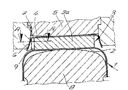
A cook~nq utensil can comprise a contalner 1, a
container base 2, a pla~e 3 o~ easily sliding material and
a cap 4 on plate 3.
FIGS. 1 to 4 ~how tho coolc~ng v~soel wlth the
container 2 and the cap 4 on the base. The container 1 and
cap 4 are made of stainless steel. Plate 3 can be mad~ o~
20 an aluminum alloy. It 1~ intermetallically bon~ed to the
container base 2 and the cap 4 by the.~ethod according to
the lnvention. ~he de~ails thereo~ have already ~een
de~cri~ed.
In the embodiment shown in FIGS. 1 and 2, use is
-- 12 --
-- 207~9~
~ads o~ a d~e S WhiCh in the region of the cap G~l~ar 6 ha~
a ~en~ structure 7 ~hereby alr dur~ng appllc~ion o~ pulse
pre~sure can be discharged fro~ the assembly compris~ng the
aontainer base 2, the plate 3 and the cap 4.
~9 the drawing also shows, the die 5 and~or ~am 8
and/or ~ap 4 in the region of the cap colla~ 6 are designed
so t~at during appl~catlon of pul~e pre~sure, air i5
expelled before the collar 6 is placed against the
container l or ~he transitlon ~egion be~ween the contai~e~
l and the container base 2.
~ n the embodiment in FTG. 1, use is made of a die
havlng vent etructures 7 in the form of bores in the
transition region between the cap 4 and the collar 6. ~y
contra~t in the embodl~ent in FIG. 2, u6e is made oP a dle
5 which has an annular venting gap 7 in the re~ion ~etween
the die R~rua~ure and the collar 6 be~ore being shap~d.
~owards the ri~ o~ th- collar, ~he annular qap 7 wlden~ in
a wedge, a~ seen in cross~s~ion~ Consequentl~ duxlng
appllcatlon of pulse pressure, tho ram 8 i~ presoed agalnst
the aontainers 1 and abuts the co~tainer 1 when the ¢ooking
uten~il is f~nished.
As a comparison between FIGS. 1 and 3 ahow~, ~h~ plate
3 is stat~oally determined and centered on t~e cap 4
without clearanoe, owing to the centering pro~ections 9
Pormed on the rim oP plate 3. In this manner, plate 3 i~
disposed in ~ap 4 so as to be resistant to pulse pressure.
- 13 -
207491~
Accordingly, plate 3 Consists of a base membe~ 3a ~nd the
centering pro~ections 9.
As a comparison between FIGS. 4 an~ 6 show~, the pulse
pressure is guided so that dur$ng ~he formation o~ the
intermetallic bond, the matorial of the plate ba~ member
3a and the material of th~ centering projec~ions 9 ~low
together and ~oin and, during ~ubsequent pla~tic
deformation, the plate material forms a uniform rim 10
having a very uni~orm cross-section round its entire
lo periphery, and is p~e~sed into the rl~ region o~ the cap
collar 6.
"Flow joining" mean~ that the plate ma~erlal no longer
~hows an~ parting gaps or ~he l~ke, Qv~n thouqh a certain
text~re i8 recogniza~le fro~ a polished seot~on in the
region or a preformed centering pro~ection 9 in the
~inished cooking utens~l.
~ he pulse pressure is guided ~o that, durlng
~ppliaation of one or more pre~sura pulse and tho resulting
plastlc de~ormation, ~n edgQ 11 on the ri~ of the aollar
is formed in seallng-tiqht manner on container 1, resultln~
~n permanent de~ormation 12 of the container 1 and aollar
6, as oan ~e seen ~rom FIG. ~ and the magnified portlon o~
FIG. 5. "Pressed in sealing-~ight ~anner" means
~ealed-~ight wl~h regard to the pl~stically deform~d
"~lowingl' plate ~aterial, ~ut so that air can adequately
escape as previously descri~ed.
- 14 -