Language selection

Search

Patent 2075207 Summary

Third-party information liability

Some of the information on this Web page has been provided by external sources. The Government of Canada is not responsible for the accuracy, reliability or currency of the information supplied by external sources. Users wishing to rely upon this information should consult directly with the source of the information. Content provided by external sources is not subject to official languages, privacy and accessibility requirements.

Claims and Abstract availability

Any discrepancies in the text and image of the Claims and Abstract are due to differing posting times. Text of the Claims and Abstract are posted:

  • At the time the application is open to public inspection;
  • At the time of issue of the patent (grant).
(12) Patent Application: (11) CA 2075207
(54) English Title: MOWER CONDITIONER
(54) French Title: DISPOSITIF D'AJUSTEMENT POUR TONDEUSE A GAZON
Status: Deemed Abandoned and Beyond the Period of Reinstatement - Pending Response to Notice of Disregarded Communication
Bibliographic Data
(51) International Patent Classification (IPC):
  • A01D 34/66 (2006.01)
  • A01D 67/00 (2006.01)
(72) Inventors :
  • LAURITSEN, GEORG (Denmark)
(73) Owners :
  • MASKINFABRIKEN TAARUP A/S
(71) Applicants :
  • MASKINFABRIKEN TAARUP A/S (Denmark)
(74) Agent: MOFFAT & CO.
(74) Associate agent:
(45) Issued:
(86) PCT Filing Date: 1991-02-01
(87) Open to Public Inspection: 1991-08-08
Examination requested: 1998-01-16
Availability of licence: N/A
Dedicated to the Public: N/A
(25) Language of filing: English

Patent Cooperation Treaty (PCT): Yes
(86) PCT Filing Number: PCT/DK1991/000029
(87) International Publication Number: WO 1991011099
(85) National Entry: 1992-07-31

(30) Application Priority Data:
Application No. Country/Territory Date
0267/90 (Denmark) 1990-02-01

Abstracts

English Abstract


Abstract
A mowing machine has a frame with driving wheels, which
are adjustable in height, and a yoke carrying a cutter
beam. The yoke is suspended from the frame such that it
can move up and down with respect to said frame, and the
cutter beam is swingably journalled on the yoke. The
yoke and the beam are balanced by an upwardly directed
spring force. Minor elevations on the ground just make
the cutter beam swing upwardly so that it is just the
weight of the cutter beam itself which is accelerated.


Claims

Note: Claims are shown in the official language in which they were submitted.

THE EMBODIMENTS OF THE INVENTION IN WHICH AN EXCLUSIVE
PROPERTY OR PRIVILEGE IS CLAIMED ARE DEFINED AS FOLLOWS:-
P a t e n t C l a i m s (amended twice):
1. A mowing machine of the type having a frame (10) and a
cutter beam (23) carrier means (10 or 15) which is adjust-
able in height, the weight of which carrier means and
cutter beam being at least partly balanced by spring
means, c h a r a c t e r i z e d in that the cutter beam
(23) is so hinged at the ends to the carrier means (10 or
15) as to be swingable about a horizontal axis with
respect to said means, said axis (22) being positioned
adjacent the rearward edge of the cutter beam.
2. A mowing machine according to claim 1,
c h a r a c t e r i z e d in that the carrier means is
formed by the frame (10) of the mowing machine which is
adjustable in height with respect to the driving wheels
(13).
3. A mowing machine according to claim 1, c h a r a c -
t e r i z e d in that the carrier means is formed by a
yoke (15) which is movable up and down with respect to the
mowing machine frame (10) which is adjustable in height
with respect to the driving wheels.
4. A mowing machine according to claim 1, 2 or 3, c h a -
r a c t e r i z e d in that the carrier means (10 or 15)
has adjustable abutments forming stop means (25) which
determine the end positions of the cutter beam (24) with
respect to the carrier means.

Description

Note: Descriptions are shown in the official language in which they were submitted.


WO91/11099 PCT/DK91/00029
- 1 - ;2~7SZ~
A mower conditioner
___________________
Mowing involves drivlng at a very high speed, and a short
stubble length is generally deslred. Since the field is
irregular, the cutter beam is sub~ected to rapid vertical
movements with respect to the wheels. The machine is ba-
lanced with springs 80 that the cutter beam ~ust rests on
the ground with a moderate pressure. Owing to the rela-
tively great weight of the machine and the resulting in-
ertia, the machine, in spite of good balancing, will be
subJected to very strong shock impacts on the cutter beam
with the problems this entails.
CH-510 975 discloses a mower conditioner whose cutter beam
is suspended from two long carrier arms, which are swing-
ably connected with the frame of the mower conditioner by
means of partly a hinge, partly a ball link. The cutter
beam is rigidly secured to the hinged carrier arm and ro-
tatably connected with the other by means of a ball link.
This structure reduces the ma~s to be accelerated when the
cutter beam meets irregularitles.
The inventlon concerns a mowing machine of the type stated
ln the lntroductory portlon of claim 1, and the ob~ect of
the invention is to addltionally reduce the shock lmpacts
to which the cutter beam 18 subJected when driving on an
lrregular field, while lmprovlng the ground following
ability of the cutter beam.
This obJect is achieved in that the mowing machine is
constructed as stated in the characterlzing portlon of
claim 1, since, in this structure, the cutter beam can
pivot freely upwardly when hltting an elevatlon, so that
it 18 ~ust the weight of the beam ltself which ls accele-
rated. The short dlstance between the center of gravlty of

WO91/11~9 PCT/DK91/00029
2~
-- 2 --
the cutter beam and the hinge axis entails that the move-
ments of the beam caused by lrregularities will be more in
the nature of tilting movements than distinct lifting
movements which take place when long carrier arms are
used, thereby reducing the average llfting height.
Claims 2 and 3 define two different, separately expedient
embodiments of the mowing machine of the invent~on.
The movements of the cutter beam with respect to the
carrier means may be limited in both directions by the
embodiment defined ln clalm 4. If an lrregularity is so
high that the beam plvots to stop, the upwardly directed
spring force on the carrier means will have begun raising
thls owlng to the smaller load.
Because of the free downward movement of the cutter beam
the machine can work with less ground pressure than the
known machlnes. Not only the machine itself, but also the
plants of the field will benefit from the reduction in the
shoak ~impacts.
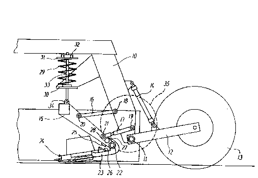
Two embodiments of the mowing machine of the inventlon are
shown schematically in vertical section in figs. 1 and 2,
respectively, of the drawing, and will be described more
fully below with reference to these figures.
In fig. 1, lO is a frame to which wheel arms 12, carring
wheels 13, are swingably secured via pivots 11. Hydraulic
cyllnders 14 are provlded between the main frame and the
wheel arms, making it posslble to ad~ust the height of the
maln frame above the ground. A yoke 15 18 movably sus-
pended from the frame 10 by means of two llnk rods 16 and
17 at each end. These llnk rods are swlngably connected
with the frame and the yoke, respectively, by means of
pivots 18, 19, 20 and 21, and form together with these

WO91/11~ PCT/DK9l/00029
- 3 ~ ~?,Q 7
parallelograms making it possible for the yoke to move
upwardly and downwardly with respect to the frame.
A cutter beam 23 is swingably secured to the lower part of
the yoke 15 by means of hlnges 22, sald cutter beam carry-
lng a plurallty of dlsc assemblies which are provided wlth
knives and are generally deslgnated 24. Stop means 25 and
- 26 on the yoke and the cutter beam, respectively, restrlct
the movement of the latter in an upward direction, and a
stop arm 27 on the cutter beam cooperates with an ad~ust-
able stop mean~ 28 on the yoke to restrict the movement of
the beam in a downward dlrection and to determine the cut-
ting angle.
The yoke 15 and the cutter beam 23 suspended from it are
balancad by means of compression screw springs 29, whose
one end rests on a flange 30 flrmly connected with the
frame lO, and whose other end engages a disc 31, which is
pressed by the sprlng against a nut 32 on the threaded
outer end of a rod 33, whlch is rotatably ~ournalled at
the lower end ln an ear 34 on the yoke. The nut 32 makes
it possible to ad~ust the spring tension.
A wlng wheel 35, throwing the harvested materlal rearward-
ly between the wheels, i8 rotatably ~ournalled in a gene-
rally known manner in the frame 10, as shown in broken
line.
Minor elevations on the ground make the cutter beam 23
plvot upwardly about the hinges 22, wlthout the yoke mov-
lng noticeably. Only when an elevat~on is so large that
the stop means 26 of the beam abuts the stop means 25 on
the yoke, will this too be lifted.
The same reference numerals are used in flg. 2 as in fig.
1 for correspondlng parts. In the structure shown in fig.

WO91/11~9 PCT/DK91/~029
_ 4 - 2~
2, the cutter beam 23 is hlnged directly to the frame lO,
and thls hinging is performed by means of the same pivots
ll as those on which the wheel arms 12 are journalled. The
compresslon screw springs 2g are here arranged between the
wheel arms and a part firmly connected with the frame lO.
In this structure, it is the entire frame which is lifted
when the stop means 26 on the cutter beam abuts the stop
means 25, which i8 here arranged on the frame.
The constructive details in the mowing machine shown and
described may be modified in several ways within the scope
of the invention.

Representative Drawing
A single figure which represents the drawing illustrating the invention.
Administrative Status

2024-08-01:As part of the Next Generation Patents (NGP) transition, the Canadian Patents Database (CPD) now contains a more detailed Event History, which replicates the Event Log of our new back-office solution.

Please note that "Inactive:" events refers to events no longer in use in our new back-office solution.

For a clearer understanding of the status of the application/patent presented on this page, the site Disclaimer , as well as the definitions for Patent , Event History , Maintenance Fee  and Payment History  should be consulted.

Event History

Description Date
Application Not Reinstated by Deadline 2001-02-01
Time Limit for Reversal Expired 2001-02-01
Deemed Abandoned - Failure to Respond to Maintenance Fee Notice 2000-02-01
Inactive: Status info is complete as of Log entry date 1998-02-25
Inactive: Application prosecuted on TS as of Log entry date 1998-02-25
Inactive: RFE acknowledged - Prior art enquiry 1998-02-25
Request for Examination Requirements Determined Compliant 1998-01-16
All Requirements for Examination Determined Compliant 1998-01-16
Application Published (Open to Public Inspection) 1991-08-08

Abandonment History

Abandonment Date Reason Reinstatement Date
2000-02-01

Maintenance Fee

The last payment was received on 1999-01-19

Note : If the full payment has not been received on or before the date indicated, a further fee may be required which may be one of the following

  • the reinstatement fee;
  • the late payment fee; or
  • additional fee to reverse deemed expiry.

Please refer to the CIPO Patent Fees web page to see all current fee amounts.

Fee History

Fee Type Anniversary Year Due Date Paid Date
MF (application, 7th anniv.) - standard 07 1998-02-02 1998-01-15
Request for examination - standard 1998-01-16
MF (application, 8th anniv.) - standard 08 1999-02-01 1999-01-19
Owners on Record

Note: Records showing the ownership history in alphabetical order.

Current Owners on Record
MASKINFABRIKEN TAARUP A/S
Past Owners on Record
GEORG LAURITSEN
Past Owners that do not appear in the "Owners on Record" listing will appear in other documentation within the application.
Documents

To view selected files, please enter reCAPTCHA code :


To view images, click a link in the Document Description column. To download the documents, select one or more checkboxes in the first column and then click the "Download Selected in PDF format (Zip Archive)" or the "Download Selected as Single PDF" button.

List of published and non-published patent-specific documents on the CPD .

If you have any difficulty accessing content, you can call the Client Service Centre at 1-866-997-1936 or send them an e-mail at CIPO Client Service Centre.


Document
Description 
Date
(yyyy-mm-dd) 
Number of pages   Size of Image (KB) 
Cover Page 1993-12-11 1 11
Abstract 1993-12-11 1 12
Description 1993-12-11 4 126
Drawings 1993-12-11 2 30
Claims 1993-12-11 1 30
Representative drawing 1999-08-24 1 14
Reminder - Request for Examination 1997-10-01 1 117
Acknowledgement of Request for Examination 1998-02-25 1 173
Courtesy - Abandonment Letter (Maintenance Fee) 2000-02-29 1 185
PCT 1992-07-31 21 597
Fees 1999-01-19 1 39
Fees 1998-01-15 1 39
Fees 1997-01-28 1 40
Fees 1996-01-15 1 38
Fees 1995-01-12 1 35
Fees 1994-01-18 1 31
Fees 1993-01-13 1 28
Fees 1992-07-31 1 25