Note: Descriptions are shown in the official language in which they were submitted.
1204-1
2a75222
MODULAR RECLINING CHAIR AND METHOD
BACKGROUND OF THE INVENTION
The present invention relates generally to reclining chairs and, more particularly,
to a method for assembling an improved reclining chair from pre-assembled modular
components.
S T(aditionally, reclining chairs are e~ui,~ped with an actuation mechanism which
is operatively interconnected between a prefabricated chair frame and a stationary base
assembly. In general, the actuation mechanTsm is a combination of various mechanical
linkages operable for providing various comfort features such as independent reclining
movement of a seat assembly as well as actuation of an extensible leg rest assembly. Due
to its relative complexity, it is common practice in the furniture industry to asse",ble the various
mechanical linkages of the actuation mechanism into a stand alone mechanism frame
asse")bly. A prefabricated U-shaped chair frame is frequently bolted around the mechanism
frame with the open portion of the "U" corresponding to the front of the chair. In addition, the
- seat assembly is supported from the mech~r.ism frame assembly for reclining movement with
respect to the chair frame. Accordingly, such reclining chairs having a mechanism frame within
a wood chair frame are commonly referred to as having a 'Yrame within a frame" construction.
As such, most furniture manufacturers do not upholster the exterior surfaces of the
prefabricated chair frame until after the mechanism frame assembly has been installed.
Unfortunately, the ~,pl~Glslering operation is very inefficient and expensive in that the frequently
heavy and aJ",bersG",e prefabricated chair frame must be manually manipulated in an
extremely labor-intensive manner.
In traditional reclining chair construction technique, the free ends of the U-
shaped frame are attached on opposite sides at the front of the mechanism frame. However,
~ 2a~5~2
the conven~ional mechanism frame typically comprises a narrow rail as the front frame member
in order to prevent interference with the pantograph linkage that protrudes from the front of the
chair during extension and retraction of the leg rest member. Accordingly, due to the small
connection surface between the free ends of the U-shaped chair frame and the front member
of the mechanism frame, the free ends of the U-shaped chair frame, which typically comprise
chair arms, are susceptible to an undesirable degree of lateral deflection when side-to-side
pressure is applied to the chair arms.
While many convenlional reclining chairs operate s~tisfactorily, furniture
manufacturers are continually striving to develop improved frames and actuation mechanisms
10 for reducing system complexity and increasing structural soundness and smoothness of
operation as well as occupant comfort. Furthermore, there is a continuing desire to develop
improved fabrication and assembly techniques which will result in reduced costs while
promoting increased efficiency and improved product quality.
SUMMARY OF THE INVENTION
In accordance with the principles of the present invention, an improved method
for asse",bling an article of furniture is disclosed which is designed to overcome the
disadvantages traditionally associated with fabricating, assembling and upholstering reclining-
type chairs. Therefore, a primary object of the present invention is to provide a reclining chair
which can be simply, efficiently, and rigidly assembled so as to significantly reduce its overall
20 complexity, weight, and cost while providing improved operation and comfort to the seat
occupant.
2~222
.,. ~
It is an additional object of the present invention to provide a three-way reclining
chair which is adapted to permit seiective and independent "reclining" movement of a seat back
relative to a seat member as well as actuation (i.e. extending and retracting) of a leg rest
assembly. As such, the presen~ invention provides a reclining chair wherein the minimal force
5 achieved via shifting the weight of the seat occup~nt is utilized as the primary means for
moving ~e seat asse-"bly between an ~uprighr position and a ~reclinedU posilion.
It is another object of the p,esenl invention to reduce the input force exerted by
the seat occup~rlt for s,noother operation of the actuation mechanis",. As a related object,
the complexity of improved actu~tion mechanism has been significantly simplified to incorporate
10 mechanical linkage and drive co, nponents optimally designed for substantially reducing
frictional losses so as to promote easier and smoother actuation. Moreover, the various
operative linkages are designed to permit Upre-assembly'' of the actuation mechanism without
utilization of a conventional mechanism frame assembly.
It is still another object of the present invention to provide a simplified recliner
15 chair frame which is structurally rigid, easy to assemble, and reduces lateral or "side-to-side"
: deflection of the chair arms.
In a preferred embodiment of the present invention, the integrated or Uknock-
down" construction of the reclining chair facilitates application of unique fabrication and
assembly techniques which effectively result in increased production efficiency and cost savings
20 while conco",itanlly producing a high-quality article of furniture. In general, the construction
of the reclining chair is such that the pre-assembled Actu~tion mechanism cannot be divorced
*om the pre-upholstered frame co",ponenls which, when asse")bled, are rbidly i,llerconnected
to define a ~box-like~ chair frame or body from which the pre-assembled ~ct~ ion mechanism
2~752~2
is integrally suspended. In this manner, the conventional construction of supporting the
actuation mechanism within a separate and distinct mechanism frame assembly is no longer
required. The pre-assembled ~ctl~ation mechanism includes a drive rod and a front support
shafl which are each directly supported be~,~fecn lefl and right upholstered side frame
5 assemblies. As such, extremely precise alignment of the actlJation mechanism with respect to
each of the separate pre-l,pholstered frame cG",ponents is possible. Moreover, unique front
and rear cross-rail asse",tl-es intercGnnect the lefl and right side frame asse" ~I es to define
a "unitized" and extremely rigid box-like chair frame or body for inhibiting side-to-side flexion
of the actuation mechanism suspended therein as well as of the side frame assemblies
10 themselves. In addition to the structural and functional advantages ~ssoci~ted with the
modular reclining chair of the present invention, a unique method of assembling the pre-
assembled actuation mechanism as an integrated component within the pre-upholstered frame
components is disclosed.
The leg rest assembly may be operated by the seat occupant rotating an
15 actuator lever through a limited angle which, in turn, rotates the drive rod for selectively
extending or retracting a pair of leg rest pantograph linkages. The pantograph linkages are
uniquely suspended for synchronous actuation between the drive rod and the front support
shafl and protrude through elongated apertures provided in the front cross-rail assembly. In
addition, an over-centered toggle mechanis"~ is provided to assist in extending and retracting
20 the leg rest assembly and in retaining the leg rest asse",bly in its "extended" and "stowed"
positions.
Furthermore, the presen~ invention relates to an improved co",~.nalion reclining
and plalforr,~ rocking chair which can be used as a convenlional rocker or as a reclining chair.
~ 2075222
The combination reclining/rocking chair is constructed and balanced such that normal rocking
movement between the chair body and the stationary base assembly is permmed without
causing the seat asse,nbly to recline, but which can be quickly and easily reclined when
desired. In addition, latching means are provided for pe""itLing the seat occupant to
5 selectively ~lock" the chair body in a multitude of rearwardly ~tilted" positions to arrest the
rocking action upon initial e~tension of the leg rest assembly to its e~tended position.
Il,dependen~ o1 such action, slight backward pressure applied to the seat back is operable to
initiate ,eclining movement of the seat asse"lbly. Accorclingly, an infinite number of reclined
positions may be achieved upon the seat occupant shifting his or her body weight against the
10 seat back.
Additional objects, advantages, and features of the present invention will become
apparent from the following description and appended claims, taken in conjunction with the
accompanying drawings.
DESCRIPTION OF THE DRAWINGS
Figures 1A through 1D are perspective views of an exemplary reclining chair
apparatus shown in various operative positions, the "modular" components of which have been
fabricated and assembled in accordance with the principles of the present invention;
~ 207~22~
. .".~.
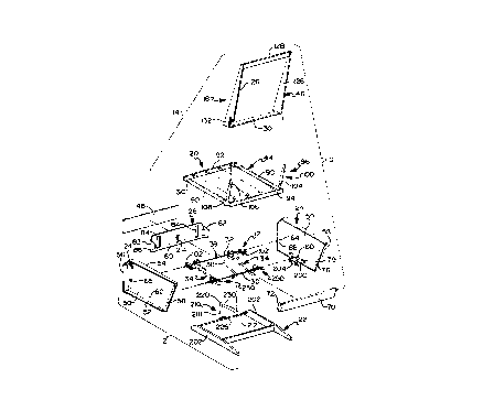
Figure 2 is an exploded perspective view of a reclining chair of the type shown
in Figure 1 with upholstery, springs and other parts removed from the pre-assembled
components for illustrating their integrated and interdependent association with an improved
actuation mechanism;
Figure 3 is a partial plan view of the reclining chair shown in Figure 2;
Figure 3A is a partial plan view of the reclining chair of Figure 3 showing an
alternative embodiment of support shaft 32.
Figure 4 is a sectional view, taken along line 44 of Figure 3, illustrating the
reclining chair in an Uupright'' position; and
Figures 5A through SH are various perspective views provided to illustrate a
prefer,ed method for assembling the reclining chair apparatus of Figures 1 and 2.
DETAILED DESCRIPTION OF THE INVENTION
In accordance with the teachings of the present invention, an improved actuationmechanism for use in single and multi-person articles of furniture (i.e. chairs and sofas or
Joveseats) is disclosed. In addition, the present invention is also directed to a method of
assembling the improved actuation mechanism as a pre-assembled and "integrated" component
of a reclining-type chair or the like. As will be described, the pre-assembled actuation
mechanism is uniquely suspended in a ~fixed" three-pivot-point arrangement from integral pre-
upholstered box-like frame cG",ponents so as to provide precise mechanical -"gr""er,l and
superior structural rigidity while conc6i"itantly fac;l;taling ap~licAtion of highly efficient
labrication and asse,nbly processes.
207522~
. ...
The actuation mechanism of the present invention is a "three-way" mechanism
which can be actuated to independently "!ecline" a seat back relative to a seat member or
move a leg rest assembly between ~retracted" and Uextended'' positions. Moreover, a full range
of independent ~recliningU movement of the seat back relative to the seat member is possible
regardless of the operative posilion of the leg rest assembly between its fully ~retracted" and
~extended" posilions.
In the disclosed embodiment, the article of furniture is shown as a combination
recliner and platfor", rocker, I,ere;.,afler referred to reclining/rocking chair 10, which includes
a pre-asse",bled actuation mechanism 12 and various upholstered frame components that can
10 be quickly and simply modularly assembled as a seating unit. Such Umodular'' construction
provides a sign-~icant advancement over conventional furniture fabrication and assembly
techniq.Jes since manipulation of heavy and cumbersome "unitized" chair frames during
upholstery installation is no longer required. As such, each frame component or frame sub-
assembly can be upholstered prior to modular assembly to actu~tion mechanism 12 so as to
1~ improve individual component quality as well as overall system quality and production
efficiency. Moreover, since actuation mechanism 12 of the present invention is relatively
compact in size, the use of loose upholstered cushions, which is an important feature in
marketing various styles of chair, sofa or loveseat furniture, is also possible.
With particular reference now to the drawings, the func~ional and structural
20 ~spects of Actu~tion mecl,anisl" 12, shown operably suspended from the various pre-
upholslered box-like frame components of recliner/rocker chair 10, will now be described.
More particularly, Figure 1A depicts an exe,nplary combination reclining/r~cking chair 1 û having
its seat assembly 14 shown in a fully ~upright" posrtiGn for permitting a seat occupant to enjoy
20~-222
~",,.
conventional seating. Figure 1B illustrates reclining/rocking chair 10 in the ~upright" position
with its associ?ted leg rest assembly 16 shown prot,acted to its "extended" position.
As seen in Figure 1C, seat asse"~bly 14 includes a seat back 18 shown in a
~reclined" posilion relative to a seat ~nel"ber 20 while leg rest asse",bly 16 is posilioned in its
5 retracted or ~stowed" position. As is known, reclining movement of seat asse"~bly 14 is
acco",plished by the seat OCCUp~lt deliberately applying pressure to seat back 18 such that
a seat swing mechanism causes seat member 20 to move forwardly and upwardly for
maintaining seating comfort while the included angle increases therebetween. Chair 10 may
be easily returned to its "upright" position upon deliberate application of rearward pressure to
10 seat assembly 14 or, more simply, if the seat occupant leans forward to remove pressure from
seat back 18. Finally, Figure 1 D shows seat assembly 14 of chair 10 in the Ureclined" position
with its respective leg rest assembly 16 protracted to the Uextended'' position. In accordance
with the embodiment shown, and as will be described trom the following disclosure, the entire
chair body 21 can be easily "rocked" with respect to stationary base assembly 22.
1~ In accordance with a primary design feature of the present invention, the various
pre-assembled and u~hGlslered frame components provided for operably suspending actuation
mechanism 12 within reclining/rocking chair 1û will now be clearly described. For purposes
of clarity, Figure 2 shows the various pre-assembled frame components with their upholstery,
padding, springs, etc. removed to better illustrate the interdependency of the trame components
20 construction which can be rapidly and rigidly assembled in a relative easy and e~f;c;enl manner.
Therefore, all of the frame components can be individually fabricated or sub-asse",blEd to
include the reqlJisite brackets, springs, padding and L~ph~ls~ery on an ~off-line~ batch-type basis.
207~222
."
ThereaRer, the various pre-assembled and upholstered frame components are assembled for
totally integrating actuation mechanism 12 therein.
As seen in Figures 2 through 4, actuation mechanism 12 of reclining/rocking
chair 10 is inlegraled into and operably suspended from leR and right side frame assemblies
524. In addition to side frame assemblies 24 reclining/rocking chair 10 also includes front and
rear rail assemblies 26 and 28, respe,1i~/ely which when i"lerconnected define a rigid box-
like chair frame. As will be described in greater detail hereinafler actuation ",echani~", 12 is
pre-assembled to include a drive rod 30 and tront support shaft 32 both of which are spatially
oriented to be precisely located and Ususpended from left and right side trame assemblies 24.
10With continued reference to Figures 2 through 4 actuation mechanism 12 is
shown to support leg rest assembly 16 thereon. More specifically leg rest assembly 16
includes leR and right pantograph linkage mechanisms 34 and leR and right spring-assisted
toggle mechanisms 36 which are operably associated with drive rod 30 and front support shaR
32 for permitting the seat occupant to selectively actuate leg rest assembly 16. A rigid cross-
15brace 38 is secured between drive rod 30 and support shaR 32 for providing structural rigidity
within actuation mechanism 12. One end of cross-brace 3~ is journally supported on drive rod
30 while the opposite end thereof is configured as a bracket 39 which is fixedly secured (such
as by a suitable threaded fastener) to an inner surface of front rail assembly 26. Furthermore
support shaR 32is fixed to an intermediate portion of cross-brace 38 via a spacer clip 40 to
20inhibit rotalion of support shaft 32 upon rotation of drive rod 30. In the preIer,ed construction
drive rod 30 is an elongaled square shaR having a handle portion 42 provided adjacent an
uphols~ered exterior portion of one of side trame asse"-~' es 24 that can be easily reached by
a person seated in chair 10 for convenient actuation thereof.
_ g _
2075~22
As best seen in Figure 2, most of the structural frame components such as side
frame assemblies 24, front rail assembly 26, rear rail assembly 28, seat frame 44, seat back
frame 46 and leg rest frame board 48 are each constructed in a manner which enables them
to support springs, padding, upholstery, etc. in order to cG",~lete a decorative and stylish
5reclil-i"g/locking chair 10 similar to that shown in Figures 1A through lD. ~efe,ably, each
of these frame component~ is fabricated from one or more wood panels and/or rails that are
fixedly secùred together by suit-~!e fasteners, such as dowels, staples, nails and screws, and
which may be reinforced at critical joints by metal re.nrorce",ent plates or brackets and/or
wood corner blocks in a known manner. As previously noted, each frame component is
10individually pre-assembled for subsequent assembly into a modular chair 10. However, it is
to be understood that the specific construction shown for each frame component is merely
exell~plary in nature.
Left and right side frame assemblies 24 are each constructed as rigid, roughly
rectangular frame components having a universal side panel 50 and horizontal bottom and top
15members 52 and 54, respectively, with top members 54 also functioning as chair arms. Each
side frame assembly 24 also includes a front post 56 which preferably has at least a lower
portion substantially perpendicular to the floor. In addition, each side frame assembly 24 has
an inclined rear post member 58 such that front and rear posts 56 and 58, respectively, and
top and bottom horizontal members 54 and 52, respectively, are each rigidly secured to a side
20panel 50. Moreover, side panels 50 have a first set of aligned bores 60 formed therein that
are sized to receive opposite ends of drive rod 30. In addilion, sleeve journals 62 are retained
within bores 60 and are sized to permit rotation of drive rod 30. As such, aligned bores 60
define a first set of ~Ixed" pivot or suspension points that are seated directly within side panels
-- 10 --
- ~7S222
,
50. In this manner, drive rod 30 has a fixed pivot arrangement and not a conventional
~floating" type which typically required additional linkages.
Side panels 50 also include a second set of aligned bores 64 oriented to receive
opposite ends of support shaft 32 therein. Aligned bores 64 are interrupted by a scab block
5 65 secured to an exterior surface of side panels 50 to define ~blind bores" for assisting in
properly aligning (i.e. centering) support shaft 32 within chair 10 upon final assembly of the
various frame components. As previously noted, spacer clip 40 positively locates rigid cross-
brace 38 with respect to support shaR 32 for maintaining the desired "side-to-side~ positioning
of support shaft 32. As such, aligned bores 64 are seated directly in side panels 50 to define
1 ~ a second set of "fixed" pivot or suspension points. Since the first and second sets of aligned
bores 60 and 64, respectively, are oriented in a predetermined arrangement on side panels 50,
it is apparent that all critical hole locations for leR and right side panels 50 may be drilled in
a single operation. Therefore, pre-assembly of actuation mechanism 12 falc,"tales "final"
assembly of chair 10 since drive rod 30 and support shaft 32 are oriented and retained (via
cross-brace 38) for receipt within aligned bores 60 and 64, respectively. Side panels 50 do
not become "left" or "right" until the members 52, 54, 56, and 58 are affixed, and sleeve journals
62 are installed in aligned bores 60, and T-nuts are inserted within bores 79 and 88 (described
below). By thus providing side panels 50 as a universal component, the accuracy of locating-
aligned bores 60 and 64 is greatly enhanced.
With continued reference to the exploded perspective view of Figure 2, means
for rigidly securing front and rear rail assemblies 26 and 28, respectively, to side frame
asse",blies 24 for integrally suspending ~ctuation mechanism 12 within a rigid "box-like" chair
frame is ci;sclosed More particularly, rear rail assembly 28 includes a laterally extending cross-
-- 11 --
2075222
"""
member 70 and left and right sngled brackets 72 secured to the inner tace surface thereof.
One or more locator pins or dowel pins 76 provided on the opposite ends of cross-member
70 are adapted to be inserted into cGIlespon~;ng sets of aligned locator holes 78 formed in
side panels 50 for properly locating rear rail asse",bly 28 with respect to side frame assemblies
5 24. Thereafter, suKable fasleners are used for fixedly securing angled brackets 72 and, in turn,
rear rail asse",bly 28 directly to the inner surface of side panels 50. Preferably, T-nuts are
retained within bores 79 formed in side panels 50 for receiving threaded fasteners therein to
rigidly secure rear rail asse"~bly 28 betv.eEn the left and right side frame assemblies 24.
Typically an upholstered rear "tailgate (not shown) is stapled to rear cross-member 70 since
1D cross-member 70 is not generally upholstered.
Front rail assembly 26 includes a laterally extending planar front cross-member
80 having rearwardly extending side plates 82 fixedly secured in close proximity to its opposite
lateral ends. As will be appreciated, front cross-member 80 includes enlarged apertures 84
which are sized to permit leg rest pa"lGg,aph linkages 34 to move therethrough during
15 extension and retraction of leg rest assembly 16. In addition front cross-member 80 is
upholstered prior to assembly between side frame assemblies 24. Side plates 82 include bores
86 which are alignable with bores 88 formed in side panels 50 to permit front rail assembly 26
to be rigidly secured between left and right side frame assemblies 24. Again in a preferred
construction, T-nuts are retained within bores 88 for receiving suitable threaded fasteners
20 therein.
Frorrt cross ,nember 80 is considerably deeper in top to bottom dimension than
front ."ecl,anis", frame ,l~e",ber~ utilized in many convenlional recliner chairs. Whereas the
latter may have a top to bottom dimension ranging from approxi",ately 314 inch to 1 1/2 inches,
-- 12 --
207~22~
the front cross member 80 has a corresponding dimension of approximately 8 inches at its
lateral ends. This increased d;.nension provides a substantially broader surface for connection
of the front rail assembly 26 to side frame assemblies 24. When assembled this increased
connec~on surface and box-like construction results in a very rigid chair frame. In addition,
5 the enlarged connection surface enhances the rigidity of the chair arms thereby significantly
reducing any deflection of the arms due side-to-side pressure applied thereagainst.
Undesirable amounts of such deflection are common in prior known recliner chairs in which
the minimal connection sunace between the chair arms and the front member of the
mechanism frame acts like a "pivot" or ~point type connection.
10For additional structural frame rigidity and to eliminate any potential for
squeaking between frame components, front and rear rail assemblies 26 and 28 may also be
glued to side frame asse"lblies 24 (in addition to the use of conventional fasteners). In
carrying out this step, glue is applied between dowel pins 76 and locator holes 78 of side
frame assemblies 2B. Glue is also applied between side plates 82 of front rail assembly 26
15 and side frame assemblies 28. When the structural frame components of chair 10 are glued
together the front and rear rail assemblies 26 and 28 are no longer readily disassembled from
~- side frame assemblies 24 for servicing Actuation mechanis") 12 in a conventional fashion
should the need arise. When the structural frame components of chair 10 are glued together
the Actuation mechanis", 12 still is carAhlc of being disassembled for servicing. To
20 acco",plish such ~lis~sse"~bly support shaft 32 is cut at a location that cGrlesponds to the
center of the sprlng clip 40 that is attached to support shaft 32 at cross-brace 38. The two
halves 32a and 32b of support shaft 32 that are created can then be re,"o~ed from the aligned
bores 64 and the various cb",ponents of ~ctllation mechanis", 12 susper,ded ll,ere~,o", can
-- 13 --
'~ ~075~
also be removed by removing the rer"ai.-ing spring clips 40 and sliding each of the halves 32a
and 32b laterally away from bores 64. H it is necessary to service the drive rod 30 or any of
the co"~ponenls of a~tion mechanis,n 12 suspended therefrom drive rod 30 can be
removed from the actuation mechanism by removing spring clip 40 and spacer clips 41 and
simply sliding the drive rod laterally away from chair 10 through one of aligned bores 60.
When the service work on chair 10 is co")~l~tecl ~ctu~tion ,necl-anisn, 12 is reassembled by
threading drive rod 30 through one of aligned bores 60 and the various actuation mechanism
components that are to be suspended ll,ereho", until drive rod 30 is journally situated and
aligned in both aligned bores 60. Spring clip 40 and spacer clips 41 are then reinserted. In
similar fashion one end of each of (the same or new) halves 32a and 32b of support shaR 32
is threaded through the various actuation mechanism components that are to be suspended
therefrom until the end is positioned in one of the aligned bores 64. A cylindrical coupling 101
is then slid over the free end of one of the support shaR 32 halves. When the free ends of
shaft 32 are aligned the cylindrical coupling 101 is then slid laterally over both ends to retain
1~ the halves of support shaft 32 in proper alignment. As shown in Figure 3A, cylindrical coupling
1 01 is positioned with respect to the free ends of halves 32a and 32b so that it abuts against
the right hand edge of cross-brace 38. Spring clip 40 that is attached to support shaR 32 at
cross-bores 38 can still be reinserted to prevent rotation of support shaR 32 once the coupling
101 iS in place.
As best seen in Figure 2 and 3, seat trame 44 is located between and supported
for reclining movement on side frame assel"blits 24. More specifically, seat frame 44 is a rigid
rectangular structure having left and right side bars 90 which are rigidly secured to opposite
ends of front and rear cross pieces g2 and 94, respectively. In view of the co",pact nature of
20~S222
., ". .,. '
actuation mechanism 12, seat frame 44 is non-contoured (i.e. ~flat") which also permits use of
loose cushions, if desired. Seat frame 44 is supported for movement relative to side frame
assemblies 24 by means of a seat swing mechanism 96 for causing seat frame 44 to move
substantially hGri~o,)tally and slightly up or down, depending on whether seat frame 44 moves
5 forwardly (during ~reclining" movement) or rearwardly (on return to the ~upright" position).
Seat swing mechanism ~6 includes left and right hand rear swing linkages 100 and left and
right hand front slide brackets 102. Rear swing linkages 100 extend ve,lically well above the
level of seat frame 44 along rear posts ~8 of side frame asse,nblies 24. Each rear swing
linkage 100 includes an elongated swing link 104, a support bracket 106 and a seat bracket
108. An upper end of each swing link 104 is pivotably connected just below chair arm 54 to
support bracket 1 06 which, in turn, is fixedly secured to its corresponding side panel 50. As
such, pivot points 110 between swing links 104 and support brackets 106 define a third set
of "fixed" pivot or suspension points that are seated directly in side panels 50.
The lower end of each rear swing link 104 is pivoted about a pivot point 112 to
1 5 an upstanding post section 114 of seat bracket 1 08. Seat bracket 1 08 has a hori~or,lal flange
portion that is securely fixed (such as by wood screws) to an underside surface of a seat side
bar 90 in relatively close proximity to the back end of seat frame 44. As such, loading on the
rear of seat frame 44 passes from seat brackets 108 and pivots 112 into rear swing links 104
as tension loading which is transferred by way of pivots 110 and support brackets 106 into
side frame asse"lt',es 24 of chair 10. Rear swing links 1 04 are elongated to provide increased
leverage for balanced reclining action. Thus, the rear of seat frame 44 moves much like a
co"trlcl'ed pendulum on and below upper pivots 110. Accordingly, seat 20 can be pre-
asse",~!ed and ~,phol-~ered prior to final asse"~bly. While not considered necessAry to provide
207~222
~,.. .
superior balanced comfort, lefl and right tension springs (not shown) may be installed between
seat bracket 108 and a rearward stationary chair frame component to provide augmented
resistance to reclining movement of seat assembly 14 for heavier seat occup~nts.As mentioned, seat swing ."echanis", 96 also includes a pair of (i.e. IeR and
right) front slide brackets 102 which are operable to guide and limit fore and afl movement of
seat frame 44 and, in turn, seat 20. More particularly, front support shafl 32 extends through
lost-motion slots 116 formed in left and right slide brackets 102 which have horizontal flanges
118 securely fixed (such as by wood screws) to an underside surface of seat side bars 90 in
relatively close proximity to the front end of seat frame 44. In addition, slide brackets 102 also
include elongated vertical flanges 119 which are adapted to be retained against the inner side
surface of seat side bars 90.
As will be appreciated, the angularity and length of slots 116 define the range
of fore and afl movement of seat frame 44 relative to chair body 21 upon the seat occupant
applying a force to move seat assembly 14 between the Uupright'' and Ureclined'' positiGns. In
addition, means are also provided for generating a predeler,nined amount of frictional drag
upon movement of seat ~ame 44 with respect to support shaft 32. In particular, a nylon insert
120 is fixedly retained within lost-motion slots 116. Compression springs 122 are provided
which concenllically surround opposite ends of support shafl 32 for biasing a disk-like washer
124 into frictional engagement with an inner surface of nylon insert 120 adjacent slot 116.
Nylon insert 120 is opersble with cG.,.pression springs 122 for controlling triction resi~lance to
movement of the front end of seat asse,nbly 20 with respect to support shafl 32 while
conco",itarltly acting to effectively ~lal"pen noise. Lefl and right spacer dips 40 are provided
for preload;.-g springs 122 and for positively locating and retaining pantGg,aph.c Ieg rest
-- 16 --
2 0 7 5 ~ 2 2
linkages 34 on support shaft 32 while inhibiting rotation of support shaft 32. Therefore,
slide brackets 102, inserts 120, washers 124, springs 122 and spacer clips 40 are pre-
assembled onto support shaft 32.
Seat back 18 is constructed to include seat back frame 46 that is in the form
of a rigid relatively re~lanylllar assembly. Seat back frame 46 includes right and left hand
side members 126 and upper and lower cross-pieces 128 and 130, respectively. As is
known, seat back frame 46 can be removably mounted on an upper portion of rear swing
links 104 by means of slide brackets 132 secured at suitable locations on side members
126. In general, slide brackets 132 are channel-shaped to provide an interior track that
slidably receives rear swing links 104 therein. When slide brackets 132 are mounted on
rear swing links 104, seat back 18 is, in effect, an extension of rear swing links 104 above
pivot points 110. As such, seat back 18 can be pivoted about pivots 1 t 0 for acting as a
lever arm for causing relatively easy angularly movement of rear swing links 104 and fore
and aft movement of seat 20.
Leg rest assembly 16 is shown to include frame board 48 having an outer
surface that is padded and upholstered so that finished reclining/rocking chair 10 will be
as seen in Figures 1 A through 1 D. Frame board 48 is supported and moved by identical
left and right hand pantograph linkages 34. Pantograph linkages 34 are subst~ntially
identical in function and structure to that shown in Figure 3 of U.S. Patent 3,096,121,
assigned to the common Assignee of the present invention, with the exception that
pantograph linkages 34 are
- 17-
207~22
,~
operably suspended about the second set of "fixed" suspension points defined by support shaft
32. For a better understanding of the operation of pantograph linkages 34, a brief description
is included herein. More particularly, frame board 48 has an angled bracket 140 secured to
its bottom face 144 for each pantograph linkage 34, whereby frame board 48 is pivotably
connected at a rear pivot 146 and a front pivot 148 to one end of board links 150 and 152,
respectively, of pantographs 34. The opposite end of front board link 152 is pivoted at 154
to an end of a connector link 156 which, in tum, is cenl,ally pivoted at 158 to a portion of rear
board link 150. The other end of connector link 156 is pivoted at 160 to a top end of a long
support link 162. The other end of rear board link 150 is pivoted at 164 to one end of a
curved link 166 which is pivoted at a central pivot 168 to a central portion of long support
link 176. The other end of curved link 166 is pivotably connected at pivot 170 to front support
shaft 32. As noted, left and right spring clips 40 are provided to maintain the desired spacing
between left and right pantograph mechanisms 34 on support shaft 32.
Another point of support is pivot 176 at the curved bottom end of long support
1~ link 162 which connects support link 162 to a first end of a drive link 178, the other end of
which has a square aligned hole through which square drive rod 30 extends such that drive
link 178 is driven by angular movement of drive rod 30. Thus, selective rotation of drive rod
30 turns drive link 178 which acts through pivot 176 to move long support link 162. Such
movement of support link 162 causes curved link 166 to swing about 'Yixed" pivot 170 by virtùe
of pivot connection 168 that curved link 166 has with long support link 162. The action of link
166 swinging about fixed pivot 170 acts to move rear board link 150 outwardly and upwardly.
In addition, pivot 160 at the top end of long support link 162 causes connector link 156 to
swing about pivot 158 such that front board link 152 is also moved outwardly and upwardly.
-- 18 --
- ~ n 7 5 2 2 2
Thls extensible action takes place simultaneously with both the left hand and rlght hand
pantograph linkages 34 when there is sufficlent angular rota~ion oS drive rod 30 via handle 42.
In this manner, frame board ~ is moveable between its 'stowed" vertical position and Hs
~extend" protracted position.
l~s best seen in Figure 3, drive link 178 is generally U-shaped having parallel
short and long legs 182 and 184, respectively, Joined by a base portion 186 which overlies
.drlve rod 30. Both legs 182 and 184 have square aligned holes through which square drive
rod 30 extends. When leg rest assembly 16 Is protracted to its fully ~extended" position, a cold
deformed stop tab 186 on long leg 184 contacts a stop shoulder 18B formed on the lowsr end
of long support link 162 when long leg 184 and link 162 are almo~P in relatively collinear
alignment. Due to engagement of stop tab 186 and stop shoulder 188, further extension of
pantograph linkages 34 is inhibited such that leg rest frame 48 is held in an elevated and
generally horizontal position.
To provide means for permitting the chair frame 21 to rock relative to base
assembly 22, contoured rocker blocks 200 are provided which are secuted to inner side faces
of side panels 50. ~ocker blocks 200 are positioned to engage an upper surface of base
assembly 22 In a Urockable'' relation therewith. Rocker blocks 200 and left and right side rails
202 of base assembly 22 are interconnected by a double coil spring "rocker devlce, generally
shown at 204 . As will be appreciated, rocker spring device 204 is
2û operable to permit balanced rocking movement of chair body 21 with
respect to fixed base assembly 22 without causing seat assembly 14
- to recline inadvertently.
_ lg _
~ B
20~522~
.i~_
In accordance with another comro, l feature associated with combination
reclining/rocking chair 10, a locking apparatus 210 is provided that is operable to rele~c~hly
hold chair body 21 in any one of a plurality of rearwardly ~tilted" positions upon leg rest
assembly 16 being selectively moved to its fully extended position. Locking appara~.Js 210 is
also operable to inhibit subsequent rocking movement of chair body 21 in a forward direction
fc"av.;ng movement to a desired rearwardly ~tiltedN position. Preferably, locking apparatus 210
is a ratchet type locking mechanism that is ~t~ated upon angular movement of drive rod 30.
In general, locking apparatus 210 acts betv/~en front rail assembly 26 of chair body 21 and
forward cross-rail 212 of base assembly 22 for providing a number of sequential lockable
rearv.a,dl~ Utilted" positions. One example of a suitable locking mechanism is thoroughly
shown and disclosed in the afore-noted U.S. Patent No. 3,096,121. As incorporated into
reclining/rocking chair 10, a contoured sector or rachet bracket 214 is secured to an inner
surface of front cross-member 80 and is formed to define a plurality of teeth 21 6 thereon. A
latching bar or pawl 218 having an upper chisel-shaped end 220 is supported from base
1~ assembly 22 and is operable to lockingly engage sector teeth 216 for preventing forward
rocking movement of chair body 21 following rearward "tilting" movement thereof. As best seen
in Figure 4, latching bar 218 has a hinged bottom end constructed from a cylindrical portion
222 which is secured by a pivot 224 to a mounting bracket 226 that is securely attached to
cross-rail 212 of base assembly 22.
2D A rectangular spring wire 230 has its forward web 232 secured in a stuck-out
loop 234 formed in latching bar 218. The opposite ends of spring wire 230 are overlapped
and retained in an aperture e~tendi.-g through a cyl:ndrical bushing 240 which is itself retained
in apertures formed in opposite sides of a drive link 242. Furthermore, drive link 242 has
-- 20 --
2075222
,~.
square apertures therein which receive square drive rod 30 such that drive link 242 is fixed
for rotation with drive rod 30.
With leg rest assembly 16 fuily extended, rotation of Actu~tion handle 42 in a
forward direction (i.e. to retract leg rest assembly 16) causes corresponding rotation of drive
S link 242 which, in turn, causes spring wire 230 to be moved rearwardly for pivoting latching bar
21 8 in a direction toward drive rod 30. As such, chisel-shaped end 220 is withdrawn from one
of teeth 216 in sector bracket 214. Upon release of locking mechanism 210, chair body 21
is ~p~hlE of unrestricted rocking action in a well known manner. Likewise, when actuation
handle 42 is selectively rotated in a rearward direction for causing leg rest assembly 16 to
move to its elevated position, rotation of drive rod 30 causes simultaneous rotation of drive link
242. This action causes wire ele,nent 230 to move forwardly for forcibly pivoting latching bar
218 and thereby advancing its chisel-shaped end 220 into locked engagement with one of
teeth 216 on sector bracket 214.
If it is desired to "tilt" chair body 21 rearwardly, chisel-shaped end 220 of latch
bar 218 will sequentially ratchet over teeth 216 until the desired degree of tilt has been
reached. In this manner, the rocking components of chair 10 are effectively Nlocked-out" for
preventing chair body 21 from returning to its forward "non-tilted" position due to engagement
of chisel-shaped end 220 of latching bar 218 with one of sector teeth 216. ThereaRer, when
it is desired to lower the chair body to its horizontal position from a tilted position, handle 42
is forwardly rotated to v:ith~llaw chisel-shaped end 220 of latching bar 218 from sector teeth
216 for per",illing chair body 21 to assume its hori~ontal position while concurrently causing
leg rest asse,-,bly 16 to move to its ~stowed" position. t is to be under~tood that any suitable
locking device can be readily substit~ted for use with chair 10 of the present invention.
-- 21 --
207~222
",
As best seen in Figures 3 and 4, left and right spring-assist toggle assemblies
250 are provided which work coactively with leg rest pantograph linkages 34. Toggle
assemblies 250 provide means for securely hoiding frame board 48 of leg rest sssembly 16
in a fully retracted position against tront rail assembly 26. Toggle assemblies 250 are also
operable to sùpply a spring force for biasillgly urging leg rest assembly 16 toward one of its
extended and retracted positions. More particularly, toggle asse"~b' es 250 each include a
toggle lever 252 w~th a square hole which is mounted by means of the square hole on square
drive rod 30 for rotation therewith. Toggle lever 252 is pivotally connected at pivot 253 to tront
leg 254 of a C-shaped toggle link 256 that curves around, above and to the rear of drive rod
30 where its rear leg 258 has an opening to which one end of a helical coil spring 262 is
attached. ~t~e opposite end of spring 262 is attached to a spring pin 264 which is secured
to a rearward portion of rocker blocks 200. While not shown, tension adjustment means may
be optionally provided for adjusting the tension in spring 262. For example, the tension in
spring 262 can be adjustably relieved for a lighter weight occupallt or it can be increased for
1 5 a heavier seat occupant. Each C-shaped toggle link 256 of toggle assemblies 250 is positively
located on drive rod 30 by means of a spacer clip 41 for maintaining the desired spacing of
toggle links 256 from rocker blocks 200 and rocker devices 204 in order to avoid interference
therewith. As shown in Figure 3, spacer clips 41 also positively locate leg rest drive links 178
in theTr desired posilioll along drive rod 30.
Operation of toggle assemblies 250 will now be described in greater detail. The
location of pivot 253 below drive rod 30 and the line of action of spring 262 are such that in
the retracted position of leg rest assembly 16, the spring force acts to biaslngly hold or "retain"
leg rest asse"~bly 16. As leg rest 16 is initially extended upon slight rotalion of actuator lever
-- 22 --
207S22~
,~
42 and, in turn, drive rod 30, pivot 253 moves up and over center of an imaginary line between
the axis of spring pin 264 and the drive rod axis; Once pivot 253 is over-center, tension
loading on spring 262 assists in drivingly rotating drive rod 30 for elevating leg rest assembly
16 as rear leg 258 of link 256 is pulled toward spring pin 264. In addition, spring 262 assists
5 the seat occupant in pivoting handle 42 through the reguired actu~tion angle. In similar
fashion, toggle asse,.ll~ly 250 is adapted to utilize the spring biasing force of spring 262 to
assist in returning leg rest assembly 1 6 to its stowed position upon reverse roldlion of handle
42.
In accordance with the principles of the present invention, a unique method for
10 assembling the various Umodular" pre-assembled frame components and actuation mechanism
12 into reclining/rocking chair 10 will now be described in greater detail. In addition, the
improved method of the present invention permits sequential assembly of the pre-assembled
and/or upholstered co,nponents in a simple and efficient manner for significantly reducing
overall system complexity, weight, and cost while promoting superior quality and reliability.
1 5 With particular reference now to Figure 5A, pre-assembled actuation mechanism
12 is shown retained on a suitable holder or "jig" 300. Jig 300 includes a pair of spaced and
angularly extending stantions 302 having first and second sets of aligned notches 304 and 306,
respectiveiy. As can be seen, the first set of aligned notches 304 is provided for retaining-
support shaft 32 therein while the second set of aligned notches 306 is provided for retaining
20 drive rod 30 therein. As previously noted, the various c~",ponents associated wit~l slide
brackets 102, pantograph linkages 34, drive link 242, cross-brace 38, and toggle assemblies
250 are all operably coupled to, or suspended from, actuation mechani~", 12 prior to
interconnection with the various frame cG",ponents. Alternatively, jig 300 may be used as an
-- 23 --
2075222
~ ,,
appropriate situs tor assembling the various linkages and components associated with
actuation mechanism 12.
With reference now to Figure 5B the asse",bly step for orienting and
inlerconnecli,)g side frame asse,nblies 24 wKh actuation mechar,is", 12 is clearly shown. As
5 will be appreciated, side frame assemblies 24 have been pre-assembled to include rocker
blocks 200, spring pins 264, and rocker spring devices 204. While not shown, it is to be
understood that the requisHe padding lining, decorative upholstery and the like have also been
installed on side frame asse",blies 24 prior to asse",bly with actuation mecl,ani~", 12. As
seen drive rod 30 and support shaft 32 are of sufficient length such that side frame assemblies
1 0 24 can be retained thereon. More specifically, the upholstered side frame assemblies 24 are
positioned on actuation mechanism 12 such that the opposite ends of drive rod 30 extend
through the first set of aligned bores 60 formed in side panels 50 (i.e. the first set of ~Ixed''
pivot points). Similarly the opposite ends of support shaft 32 are seated with the second set
of aligned bores 64 formed in side panels 50 (i.e. the second set of 'Yixed" pivot points).
As seen in Figure 5C the four primary pre-assembled frame components include
left and right side frarne assemblies 24 and front and rear rail assemblies 26 and 28
respectively. In accordance with a preferred assembly procedure dowel pins 76 on opposite
ends of rear cross-member 70 are inserted with glue into locator holes 78 formed in side
panels 50 for properly aligning and locating rear rail assen,bly 28 with respect to the left and
20 right side frame asse",blies 24. Thereafler, threaded fasteners are threadably driven through
bores in angled l,rackel 72 and into T-nuts retained within bores 79 formed of side panels 50
for securing rear rail assembly 28 betvccn the left and right side frame asse"~blies 24.
Complete li-yhlening of the threaded ~aslener~ is typically deferred until tront rail asse"~bly 26
~075222
._
has also been secured to side frame asse",blies 24. As noted, an upholstered ~tailgateU (not
shown) may be secured to rear rail assembly 28 in those applications wherein rear rail
assembly 28 is not upholstered.
Following interconnection of rear rail assembly 28, glue is applied to side plates
5 82 of front rail assembly 26 and they are slid inwardly between left and right side frame
asse",blies 24 in such a ."anner to permit po,lions of pantog,aph linkages 34 to project
through apertures 84 formed in front cross-member 80. As shown in Figure 5C, rachet bracket
214 has been pre-assembled to a rear surface of front cross-member 80. In addition, front
cross-member 80 has been upholstered prior to assembly. Bores 86 formed in side plates 82
10 are aligned with bores 88 formed in side panels 50 such that threaded fasteners are thereafter
driven through bores 86 and 88 for rigidly securing front rail assembly 26 to side frame
assemblies 24. Thereafter, cross-brace bracket 39 is securely attached to front cross-member
80 to provide additional structural rigidity.
Figure 5D illustrates the integrated and interdependent relationship of the four
1 5 primary frame components which when assembled define an extremely rigid "box-like"
upholstered chair body 21 within which actuation mechanism 12 is suspended. As noted, this
"integrated" construction permits the elimination of the separate mechanisn, frame asse,nbly
conventionally provided for supporting the actuation mechanisms in prior known reclining
chairs. As seen, jig 300 is designed to permit the various frame components to be
20 interconnected in an extremely efficient manner. rOllaw;l)9 assembly of chair body 21, frame
board 48 is fixedly secured to angled brackets 140 of pantograph linl:~ges 34. Again, it is to
be understood that frame board 48 has been pre-asse",bled as an upholslered unit prior to
being assembled as part of chair body 21.
2075222
.~
With particular reference now to Figure 5E, the four pre-assembled frame
components defining chair body 21 are shown supported from jig 300 with ~ctuation
mechanism 12 integrally suspended therefrom. In accordance with the next operation,
upholstered seat 20 (which includes seat frame 44 with its appropriate upholstery padding and
springs) is interconnected to chair body 21. More particularly, notches 310 formed in the tront
underside edges of seat frame side bars 90 are provided for aligning seat frame 44 with
respect to support shaft 32. Next, rear swing linkages 100, which have been pre-assembled
onto ~pholslered seat 20, are fixedly secured to side panels 50 via support brdckets 106.
Once support brackets 106 are fixedly secured to side panels 50 (via suitable fasteners), pivot
points 110 between swing links 104 and support brackets 106 are operable to define the third
set of 'Yixed" pivot points about which seat asse")bly 14 is reclinable. Alternatively, support
brackets 106 of rear swing linkages 100 can be initially mounted directly to side panels 50
such that angled brackets 108 can be thereafter secured to upholstered seat 20. In this
manner, seat 20 can be "flipped over" to permit seat brackets 108 to be securely fastened to
side bars 90 of seat frame 44. With seat frame 44 positioned such that support shaft 32 is
located in notches 310, slide brackets 102 are pulled inwardly against the biasing force of
springs 122 until verticaily extending flanges 119 abuttingly engage the inner surface of seat
trame side bars 90. Thereafter, suitable fasteners (such as wood screws) are driven through
holes in horizontal flanges 118 to securely fix slide brackets 102 to an underside surface of
20 seat side bars 90.
With particular reference now to Figure 5F, base assembly 22 is shown pre-
asse",bled to include various co",ponents of locking apparatus 210 such as latch bar 218 and
mounting bracket 226 secured to front cross-rail 212 of base assembly 22. Chair body 21 is
-- 26 --
2075222
removed from jig 300 and is placed in proper alignment with respect to base assembly 22 such
that rocker blocks 200 rest on side rails 202 of base assembly 22. Thereafter rocker spring
devices 204 shown pre-assembled to extend downwardly from rocker blocks 20 are fixedly
secured to the inner face surfaces of side rails 202 of base assembly 22 via suitable fas~ene,s.
S Therea~ler, the opposite ends of spring wire 230 are secured to drive link 242 for compleling
the operative assembly of locking mechanism 210. Finally, Figures 5G and 5H illustrate the
manner in which uphols~ered seat back 18 can be detachably secured to seat 20 via swing
links 104 and slide brackets 130.
As is relatively apparent from examination of Figures 5A through 5H the pre-
10 assembled components can be interconnected in a number of other acceptable sequentialoperations to produce "knock-down" or modular chair 10. The method of asse"~bly disclosed
herein is advantageous in that virtually all of the components can be pre-asse".bled Uoff-line"
for quick and efficient modular interconnection in a highly repeatab!e and precise fashion.
The foregoing discussion discloses and describes an exemplary embodiment of
15 the present invention. One skilled in the art will readily recognize from such ~iscussion and
from the accompanying drawings and claims that various changes modifications and variations
can be made therein without departing from the spirit and scope of the invention as defined
in the following claims.