Language selection

Search

Patent 2075313 Summary

Third-party information liability

Some of the information on this Web page has been provided by external sources. The Government of Canada is not responsible for the accuracy, reliability or currency of the information supplied by external sources. Users wishing to rely upon this information should consult directly with the source of the information. Content provided by external sources is not subject to official languages, privacy and accessibility requirements.

Claims and Abstract availability

Any discrepancies in the text and image of the Claims and Abstract are due to differing posting times. Text of the Claims and Abstract are posted:

  • At the time the application is open to public inspection;
  • At the time of issue of the patent (grant).
(12) Patent Application: (11) CA 2075313
(54) English Title: SKI RACK
(54) French Title: PORTE-SKIS
Status: Deemed Abandoned and Beyond the Period of Reinstatement - Pending Response to Notice of Disregarded Communication
Bibliographic Data
Abstracts

English Abstract


ABSTRACT
A vehicle roof rack for skis is disclosed. The rack comprises
a base (1) which is releasably attachable to the roof of a
vehicle by a suction cup (11). Flanges (3) extend up from the
base to define a pair of channels (5) at each end. There is a
a bar (6) which is hinged to one of the end flanges and may
be locked across the rack to close the channels (5) and lock
the skis therein. In use at least two such racks are fixed
onto a vehicle roof so that the skis can be supported at
intermediate points along their length.


Claims

Note: Claims are shown in the official language in which they were submitted.

The claims defining the invention are as follows:
1. A vehicle roof rack for skis or the like comprising a base
having spaced apart upstanding flanges which are arranged to
define one or more open channels therebetween for holding said
skis, a bar means for attachment across said flanges to thereby
close said channels and releasable means for securing said base
directly to said vehicle roof.
4. The vehicle roof rack as claimed in claim 1 wherein said
releasable means is a releasable suction cup disposed below
said base.
3. The vehicle roof rack as claimed in claim 2 wherein a cam
lever is located between two of said flanges, said lever being
movable between a first position whereby said cup is deformed
so as to clamp onto said vehicle roof by vacuum pressure and
a second position in which said rack is released from the roof.
4. The vehicle roof rack as claimed in claim 3 wherein said
bar means is hinged to the top end of one of said end flanges and
is pivotal to extend across and attach to the opposite end flange
by means of a lock.
5. The vehicle roof rack as claimed in claim 4 wherein the
underside of the bar is recessed so that when said bar closes
over said channels the edges of said bar extend down on each
side of the flanges.
-6-

6. The vehicle roof rack as claimed in claim 5 wherein the cam
lever when in said first or second position extends up into the
recessed underside of the bar whereby said lever cannot be
operated when said bar is closed over said channels.
-7-

Description

Note: Descriptions are shown in the official language in which they were submitted.


SKI RACK 207~31 3
This invention relates to roof racks and more
particularly although not exclusively to racks
for carrying snow skis or the like on motor
vehicles.
STATEMENT OF PRIOR ART
Existing roof racks for skis typically comprise
a set of bars which are fitted transversely
across the roof of a motor vehicle. The bars
dre supported slightly above the vehicle by
means 3f brackets at each end which clamp onto
the drip mould channels along each side of the
roof. Such devices however have a number of
drawbacks. They are laborious to instal, they
often mar the paint finish of the vehicle and
they cannot be fitted to many late model vehicles
which do not have protruding drip moulds around
the roof.
SUMMARY OF THE INVENTION
It is therefore an object of this invention to
ameliorate the aforementioned disadvantages and
accordingly a vehicle roof rack for snow ski-s
or the like is disclosed comprising a base
having spaced apart upstanding flanges which
are arranged to define one or more open channels
therebetween for holding said skis, a bar means
for attachment across said flanges to thereby
close said channels and ~eleasable means
for securing said base directly to said vehicle
roof,

207~313
Preferably said flanges comprise a palr of end flanges and
one or more intermediate flanges therebetween with said bar
means extending across the end flanges.
DETAILED DESCRIPTION OF THE DRAWINGS
The currently preferred form of this invention will now be
described with reference to the attached illustrations in which:
which:
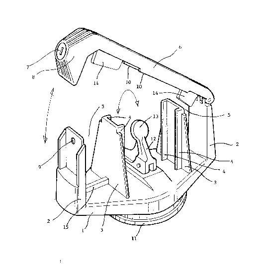
Figure 1 shows a perspective view a rack according to
to this concept with the bar closed,
Figure 2 shows a perspective view of the rack of
figure 1 with the bar opened, and
Figures 3 and 4 show.side and bottom views of the rack.
DETAILED DESCRIPIION OF PREFERRED EMBODIMENT
Referring first to figures 1 and 2 the rack may
comprise an elongated base 1 with upstanding
end flanges 2 and intermediate flanges 3. The
flanges may be stiffened by further vertical
rlbs 4 extending up along their sides. Preferably
the flanges are parallel and extend across the
width of the base at right angles to its length
to define a pair of channels 5 at each end. A
bar 6 is hinged to the upper end of one of the
end flanges and when the rack is closed it
extends across to attach onto the opposite
flange at the other end by means of a lock.
This lock may comprise a key operated tumbler 7
mounted ln an overhanging bulbous end section

207~3~
8 of the bar. Rotating this tumbler allows it
to also move axially so that a lug can be
either inserted into an aperture 9 in the end
flange 2 to lock the rack closed or withdrawn
from this aperture to open it (as shown in
figure 2). The bar 6 is preferably concave on
its underside so that the edges 10 extend down
on each side of the flanges 2 and 3. In this
way the channels can be more effectively closed
without gaps and a strong interlocking structure
lS provided.
A flexible suction cup assembly 11 of any
suitable design is located on the underside
of the base 1 and connects with an L shaped
cam lever 12 located above the base and between
the two intermediate flanges 3. In the position
shown by figure 2 with the rounded end 13 of the
lever at r1ght angles to the plane of the base
the centre of the cup is pulled upward so as
to clamp the rack by vacuum - onto any
smooth and nonporous surface such as a vehicle
roof. Preferably when in this position the end
13 of the lever extends up into the recessed underside of
the bar 6 when it is closed so that the rack mustbeopenedby
unlocking this bar before the suction mounting
can be released.
In use one or more pairs of these racks can be

207~31~
quite easily fitted to a vehicle by positioning
them one behind the other on the roof and then
rotating the cam levers l2 from a release
position ,here the rounded end 13 is parallel
to the base to the clamping position shown.
Snow skies or the like can then be placed into
the aligned channels 5 so that they are supported
at intermediate points along their length. Sub-
sequent closing and locking of the bar 6 across
the channels secures the skies to the vehicle
for transport and/or protection against theft.
As shown in figures 1 to 3 ribs 14 and 15 may
extend down from the underside of the bar 6 and
up from the base inside each of the channels 5.
The ribs 14 are also preferably mounted on
resiliently deflectable spring leaves 16 in the
bar. When the bar is closed the skis are thus
securely clamped between the opposite pairs of
ribs 14 and 15 in each channel to prevent move-
ment during transport.
It will thus be appreciated that this invention
at least in the form of the embodiment described
comprises a novel and improved form of vehicle
roof rack. Clearly however the particular example
disclosed is only the currently preferred form
of this invention and a wide variety of modifica-
~ions may be made which would be apparent to a
person skilled in the art. For example the shape

2~75313
and configuratlon of the base flanges and locklng
bar may all be modified according to application
or design preference as could the number of
~hannels provided in the rack. Also, while the
?referred material for constructing the rack is
a suitably tough and mouldable plastic the invention
extends to any other material such as aluminium or
fibreglass etc.
For the purposes of this specification expressions
such as "above", "below", "front" and "rear" refer
to the device in a position of use as illustrated
and are not to be read as necessarily limiting.

Representative Drawing
A single figure which represents the drawing illustrating the invention.
Administrative Status

2024-08-01:As part of the Next Generation Patents (NGP) transition, the Canadian Patents Database (CPD) now contains a more detailed Event History, which replicates the Event Log of our new back-office solution.

Please note that "Inactive:" events refers to events no longer in use in our new back-office solution.

For a clearer understanding of the status of the application/patent presented on this page, the site Disclaimer , as well as the definitions for Patent , Event History , Maintenance Fee  and Payment History  should be consulted.

Event History

Description Date
Time Limit for Reversal Expired 1995-02-07
Application Not Reinstated by Deadline 1995-02-07
Deemed Abandoned - Failure to Respond to Maintenance Fee Notice 1994-08-05
Inactive: Adhoc Request Documented 1994-08-05
Application Published (Open to Public Inspection) 1994-02-06
Request for Examination Requirements Determined Compliant 1993-05-27
All Requirements for Examination Determined Compliant 1993-05-27

Abandonment History

Abandonment Date Reason Reinstatement Date
1994-08-05
Owners on Record

Note: Records showing the ownership history in alphabetical order.

Current Owners on Record
LEWIS L. ROBSON
LEWIS L. ROBSON
Past Owners on Record
None
Past Owners that do not appear in the "Owners on Record" listing will appear in other documentation within the application.
Documents

To view selected files, please enter reCAPTCHA code :


To view images, click a link in the Document Description column (Temporarily unavailable). To download the documents, select one or more checkboxes in the first column and then click the "Download Selected in PDF format (Zip Archive)" or the "Download Selected as Single PDF" button.

List of published and non-published patent-specific documents on the CPD .

If you have any difficulty accessing content, you can call the Client Service Centre at 1-866-997-1936 or send them an e-mail at CIPO Client Service Centre.

({010=All Documents, 020=As Filed, 030=As Open to Public Inspection, 040=At Issuance, 050=Examination, 060=Incoming Correspondence, 070=Miscellaneous, 080=Outgoing Correspondence, 090=Payment})


Document
Description 
Date
(yyyy-mm-dd) 
Number of pages   Size of Image (KB) 
Claims 1994-02-05 2 27
Abstract 1994-02-05 1 10
Drawings 1994-02-05 4 57
Descriptions 1994-02-05 5 102
Representative drawing 1998-08-19 1 20
PCT Correspondence 1993-05-26 1 24
Courtesy - Office Letter 1993-08-10 1 46