Note: Descriptions are shown in the official language in which they were submitted.
20'~~~96
The present invention relates to a recording
apparatus, and particularly a recording apparatus in which
shading correction processing can be performed.
In the widespread use of computers and communication
apparatus, recording apparatus outputting information of
these apparatus by enabling recording heads to form
digitized dots has been general7_y used. In addition, such
digitized recording apparatus is generally applied into
copy machines. In a recording apparatus using recording
heads, in order to increase the recording speed, it is a
general habit to used a multi-head including a plurality
of recording elements. However, it is rather difficult to
fabricate a plurality of recording elements in an
individual mu7_ti-head in a uniform quality and hence, the
characteristic of fabricated recording elements may not be
stabilized. As a result, shading or density shading
(density ununiformity of an image which is recorded on a
recording medium by the reading head which has a plurality
of recording elements) occurs in the recorded image which
causes the reduction of the image quality. By repetitive
use of recording elements, recording elements suffer from
aged deterioration which also causes characteristic
instability and shading.
In order to solve above problems, what is proposed is
method for correcting characteristic of recording elements
by means that a specific read-out part for reading out
- 2 -
20'~~~9~
shading at an arbitrary time is placed in the recording
apparatus and shading correction. data are generated
according to the read-out data.
Fig. 1 shows a diagrammatic picture illustrating an
example of such a method for reading out shading as
described above.
In Fig. 1, a reference numeral 121 is a recording
sheet, 122 a recording head, 123 a recording element
placed in the recording head 122, 124 a read-out head
composed of CCD, 125 a read-out element installed in the
read-out head 124, and 126 a test pattern obtained by
scanning in the X direction the recording head 122
including recording elements 12:3 which are arranged in the
Y direction relative to the recording sheet in order to
record one line pattern. The n,.~mber of the read-out
elements in the read-out head 124 is equivalent to that of
the recording elements of the recording head 122. By
scanning the read out head 124 in the direction of an
arrow B in Fig. 1, the density of the pattern 126 is read
out. In this configuration shown in Fig. l, the number of
density data read-out by each read-out element 125 in a
single scanning operation is equal to the number of the
recording elements 123 of the recording head 122, and the
average of these density data is used as an ideal density
to be realized by individual recording elements.
Even if input signals to a7_1 the recording elements
123 of the recording head 122 are identical to one
- 3 ~-
20'~~~9~
another, in case that the read out density has shading
property, the input signals should be corrected. For
example, with respect to the recording element giving
lower density, the input signal is corrected so as to be
larger, and with respect to the recording element giving
higher density, the input signa7_ is corrected so as to be
smaller. So far, the density defined by individual
recording elements can be corrects ed to be uniform. In
case that shading occurs as the recording apparatus is
used, further shading correction is performed in order to
establish uniform density. The modification of input
signal values described above is performed by referring
conversion tables.
By referring to Figs. 2 and 3, an outline process of
the shading correction processing is described below.
Now assume that the relationship between the input
(driving) signal to a certain recording element n and the
density of the recorded (outputt:ed) image or dot is one
shown in Fig. 2. It can be staged that the recording
element n recording an image with the density ODn with
respect to the input signal S. If the average density
over all the recording elements with respect to the
driving signal S is assumed to be OD, in other words, the
correction density is assumed to be OD, the recording
element n records an image with higher density. In order
to correct the density of the recording element n from ODn
to OD, the intensity of the input signal to the recording
- 4 -
20'~~~9~
element n is modified from S to S' by referring to the
conversion table.
Fig. 3 is a graph illustrating a content of the
conversion table. The table shown in Fig. 3 contains 64
correction curves or straight lines, each of which
corresponds to a couple of an input signal S and its
corresponding output signal, each signal formed in 255
gray level data. In Fig. 3, on7_y two out of 64 lines, A
and B, are shown. Information about which correction
curve is selected to an individual recording element are
separately stored and referred in responsive to the read-
out density data in order to se7_ect a desirable correction
curve. When the input signal S is inputted with respect
to one recording element, this Element giving the density
according to the correction curve or line selected. For
example, with respect to the recording element accepting
the input signal S and outputting the density ODn,
correction line B is selected and input signal is modified
to S' so that the density recorded by that recording
element is OD .
The density distribution es~~ablished in the
configuration defined as in Fig. 1 is generally found to
be one shown in Fig. 4, where the horizontal axis
represents the position of recording elements in the
recording head, and the vertical_ axis represents the
recording density defined by individual recording
elements. One problem in this ~;ituation is that the
- 5 -
2075596
density by the recording elements at the end parts of the
array of recording elements is different from the density
by the recording elements at the rest part of the array.
That is, a pixel recorded by the recording elements at the
rest part of the array involves recorded parts by the
adjacent recording elements, on the other hand, the pixel
recorded by the recording elements of the end parts of the
array involves a part of ground of the recording sheet.
Therefore, in the case that the sheet color is white, as
shown in Fig. 4, the density at the edge parts is formed n
a gradually increasing or decreasing curve in which the
measured density is estimated to be less than the actual
density. If the density correction is performed in such a
situation, the density at the connection parts between the
recording lines repetitively developed by multiple
scanning operations of the recording head may be modified
to be greater than the actual density.
In order to solve the above problem, there is a known
correction method in which three lines (three time scan
operations) are recorded and only the central line data are
used for correction calculations. In the case of recording
three lines, recording elements at the both end parts of the
array of recording elements form pixels so as to be adjacent
to each other so that the above described problem may be
2 5 solved .
- 6 -
C
20'~~~0~
In either method for density shading correction, it
is known that several problems specific to text-pattern
read-out procedures still exist.
(1) The first problem relates to the density shading
correction in recording images by using a multi-head, for
example, in reduction recording in copy machines.
As for a method for reduction recording, what is well
known is a method that, by sele<aing input signals defined
to individual recording element:>, recording is performed
not by all the recording elements but by partial recording
elements. This method is further categorized into two
methods. Examples on these methods applied to reduction
recording in the recording apparatus shown in
Fig. 5 are described below.
Fig. 5 is an isometric view of the main part of the
recording apparatus using an ink jet recording method. In
Fig. 5, the recording head 4 has a plurality of orifices
for ejecting ink fluids in an array extended in Y
direction ejecting ink fluids corresponding to individual
orifices. The recording head 4 is guided by the guide
shaft 5 and scanned in X direction in the figure, and in
responsive to this transport movement, the recording head
ejects ink fluids and forms dots on the recording sheet 2.
By the single scan movement of the recording head, one
line recording is established. The recording sheet 2 is
fed in Y direction by the feed roller 1 driven by the
motor not shown, which establishes a plurality of line
20'~~~9~
recordings continuously. The paper press board 3 is
installed near the recording area developed by the
recording head 4 in order to ma~:e the recording area on
the recording sheet 2 flat.
In the first method of reduction recording, the
rotational movement of the feel roller 1 is controlled in
an ordinary manner, and the scan operation of the
recording head 4 is performed several times in responsive
to a single rotational movement of the feed roller 1. At
each scan operation, orifices used for recording operation
are altered by blocks. This means that, in a multi-head
having N orifices, in the first scan, orifices from the
edge to n1 are used, and in the second scan, orifices from
(n1 + 1) to n2 are used, and in the K-th scan, orifices
from n(k-1) + 1 to N are used for recording, respectively.
Owing to this sequence, reduction recording with 1/k
magnification can be performed. After terminating the
recording at the K-th scan, the feed roller 1 is rotated
in order to move the recording :>heet in the transport
distance equivalent to the N pitches of orifices. So far,
reduction recording is repeated in the same manner.
In the second method of reduction recording; the
rotational movement of the feed roller 1 and the scan
operation of the recording head 4 are altered mutually, or
the rotational angles of the feE:d roller 1 which
determines the transport displacement of the recording
sheet 2 is controlled in respon:>ive to the recording
- g _
20~~j9~
magnification. For example, in recording by using L(L <
N} orifices in the multi-head h<~ving N orifices, reduction
recording with L/N magnification can be performed, in
which the transport displacement, of the recording sheet is
equivalent to the L pitches of orifices.
In the above two methods, the number of reduction
patterns obtained by the second method is greater than
that obtained by the first method. In the first method,
as recording is performed by K times sheet feed
operations, in each time of whi<:h N orifices are used, K
must be a divisor of N and the number of reduction
patterns is limited to the number of divisors of N. On
the other hand, in the second method only if the
condition, L 5 N, is satisfied, the number of reduction
patterns is theoretically taken to a the number of
orifices. This is the reason why the second method is
usually used for reduction recording.
However, even in the above described method for
reduction recording, if the conventional method for
density shading correction is adopted, the following
problems exist.
As described above, the density of a specific pixel
to be read is affected the density of pixels adjacent to
the specific pixel. In the example of a multi-head having
n orifices (recording elements}, the correction data for
the i-th recording element includes the effect by the (i-
1)th and (i+1)th recording elements. In other words, the
- 9 -
20'~~~9~
correction data for the i-th recording element is most
effective when a pixel is recorded by the i-th recording
element between pixels defined by the (i-1)th and (i+1)th
recording elements.
Figs. 6A and 6B are recorded pixels and density
distributions in an ordinary recording condition without
density shading correction and with density shading
correction, respectively. Without density shading
correction as shown in Fig. 6A, density shading is found
to be to a relatively large extent. In contrast, in the
example shown in Fig. 6B, by altering the number of pixels
at individual recording elements instead of varying the
values of input signals, density shading in a designated
region can be reduced.
However, in case of reduction recording by using
orifices from 1 to i out of n orifices, recording is
performed in the following manner.
At first, the recording head is moved in X direction
in Fig. 5 while recording one line using recording
elements from 1 to i. Next, at the time when the
recording head is moved back to the home position, the
recording sheet is moved in Y direction by the i pitches
of recording elements which is i_/n of an ordinary
transport displacement of the recording sheet. And one
line is recorded by using recording elements from 1 to i.
In recorded images in an ordinary magnification ratio,
pixels adjacent to the pixel defined by the i-th recording
- 10 -
20'~~~96
element are those defined by the (i-1)th and (i+1)th
recording ratio, as the i-th recording element is defined
as a recording element at the edge part, the pixel defined
by this i-th recording element i.s located between the (i-
1)th recording element and the l.st recording element.
Recorded pixels and density distribution in reduction
recording after density shading correction are shown in
Fig. 6C. Density shading correcaion applied in Fig. 6B is
also applied to individual recording elements in reduction
recording in Fig. 6C. In this case shown in Fig. 6C, if
density shading correction is performed without
considering the mutual effect between recording elements
"i" and "1" which form a connect, ion part of recorded
images, density shading correction is not sufficient
enough and density shading may be contained in the density
distribution which is found to be a black or white line
noise in a recorded image. In i~he prior art, due to above
described density shading, there is a problem that the
quality of reduced recorded images is worse than that of
ordinary recorded images.
(2) The second problem relates to above described
density shading in a recording apparatus for recording
images with a plurality of different ink colors.
In reading out a test pattern recorded with a
plurality of different ink colors, the density levels of
individual ink colors are generally different from one
another. Therefore, the levels of density shading found
- 11 -
__.. 20'~~~9~
in read-out data changes in every individual color image.
If an identical density shading correction is applied
commonly to individual ink colors, density shading for
specific color tones may not re:~olved.
In order to solve this problem, a method in which a
distinctive correction procedures is applied to a specific
color tone is possible. However, this method requires a
complex apparatus structure and control process which may
lead to another new problem.
This problem is not specific to the recording
apparatus using an ink jet recording method but found in a
recording apparatus using a plurality of recording
elements and a plurality of ink colors, for example, a
thermal printer.
(3) The third problem is that, in case of using an
exchangeable recording head, density shading correction
may give a bad effect dependent of the characteristics of
the recording head.
(4) The fourth problem is that, in case that a test
pattern chart is not placed in ;~ proper position the read-
out data of the test pattern cannot be obtained precisely.
(5) The fifth problem is that, in case that a test
pattern is not recorded in a good condition on the test
pattern chart, the read-out data of the test pattern
cannot be obtained precisely.
- 12 -
._ 20'~~~96
An object of the present invention is to provide a
recording apparatus which can always make the optimum
correction of shading according to a recording head to be
used and recording mode.
Another object of the present invention is to provide
a recording apparatus which can always make the optimum
correction of shading by using a different shading
correction process, respectively, when recorded by all
recording elements of the recording head and when recorded
by a portion of recording elements.
Further object of the present invention is to provide
a recording apparatus which makes a recording by using a
plurality of colors, in which the density shading of each
recorded color is reduced with a simple construction.
Still further object of the present invention is to
provide a recording apparatus which can correct and record
input image data on the basis o:f density shading
correction data made by read-out of an image pattern
recorded by the recording head, and which can make and
renew the correction data with a high reliability.
In a first aspect of the present invention, there
provided a recording apparatus comprising:
a recording head having a plurality of recording
elements;
a test pattern recording means for recording a test
pattern;
- 13 -
2U'~~~9fi
a read-out means for reading out the test pattern
recorded by the test pattern recording means;
a correction data setting means for setting shading
correction data used when the recording head recording on
the basis of the read-out data read by the read-out means;
and
a modification means for modifying the test pattern
recording means and/or the correction data setting means
in responsive to at least one oi= a recording mode of the
recording apparatus, a state of the recording head and a
state of the test pattern recording means.
In a second aspect of the present invention, there
provided a recording apparatus f=or performing recording by
a set of pixels comprising:
a recording head having a plurality of arrayed
recording elements for forming t:he pixels;
a test pattern recording means for recording a test
pattern by using the recording head, the means recording a
test pattern by using only a part of the plurality of
arrayed recording elements, the part of the plurality of
arrayed recording elements being used for the recording;
and
a shading correction means for correcting a
characteristic of each of the plurality of arrayed
recording elements of the recording head in forming the
pixel based on the test pattern recorded by the test
pattern recording means.
- 14 -
20~~~9~
Here, the test pattern recording means may record a
test pattern so that a pixel de:Eined by one end part in
the plurality of arrayed recording elements used for the
recording may be adjacent to a pixel defined by the other
end part of the plurality of ar:rayed recording elements.
The shading correction means may correct the
characteristic on the basis of <~ read-out result of a
read-out means for reading out t=he test pattern.
Each of the recording elements may have an orifice
for ejecting ink fluid and a thermal energy generation
element for generating thermal energy for ejecting the ink
fluid from the orifice, may generate a bubble by the
thermal energy, and may eject the ink fluid accompanied by
generation of the bubble.
In a third aspect of the present invention, there
provided a recording apparatus for performing recording by
using a recording head having a plurality of recording
elements with a plurality of recording colors comprising:
a read-out means for readin~~ out data of an image
recorded by the recording head;
a density changing means fo:r changing a density level
of the read-out data by changing a reference data used for
transferring the read-out data i.n converting the data read
out by the read-out means into a recording data for the
recording head; and
a shading correction means :Eor correcting a density
recorded by each of the plurality of recording elements of
- 15 -
20"~~~96
the recording head based on the changed density level by
the density changing means.
Here, the density changing means may have a CPU, the
CPU changing a reference data of an A/D conversion circuit
for converting the read-out data into a digital signal.
The density changing means may change black data in
applying a black correction process to the read-out data.
The density changing means may change black data by
changing a black shading plate z:ead for sampling black
data in responsive to the recording color.
In a fourth aspect of the present invention, there
provided a recording apparatus recording by using a
recording head having a plurality of recording elements,
the recording head having a means for storing an
identification information of the recording head and a
first shading correction data specific to the recording
head, the first density shading correction data being
referred in recording, the apparatus comprising:
a first memory means for reading the identification
information and the shading correction data and storing
both with one being corresponding to the other;
a shading correction data making means for making a
second shading correction data by using the first shading
correction data read from the first memory mean s
a second memory means for storing the second shading
correction data made by the shading correction data making
- 16 -
20'~~~9~
means and the identification information corresponding to
the first shading correction dat;a in a coupled form;
a storing means for reading the identification
information and the first shading correction data from an
installed recording head in a designated timing and
storing both into the first memory means; and
a recording head driving means for comparing the
identification information read out from the second memory
means and a recording head identification information
stored in the first memory mean:>, the recording head
driving means driving the recording head by using the
second shading correction data read out from the second
memory means if the both identification informations equal
to each other, or the recording head driving means driving
the recording head by using the first shading correction
data read out from the first memory means if the both
identification information do not equal to each other.
Here, the designated timing may be a time when an
electric power supply to the apparatus is turned on.
The designated timing may be time when a door
installed for opening an inside of the apparatus and
accepting a work for exchanging the recording head is
opened or closed during an electric power supply to the
apparatus is turned on.
A recording apparatus may further comprise a battery
for backing up the first memory means and the second
memory means.
_ 1~ __
._ 20'~~~9~
The second density shading correction data may be
stored in the second memory means only by the shading
correction data making means.
The shading correction data making means may have a
means for making a new second shading correction data by
correcting the second shading correction data and for
revising a content of the second memory means.
A recording apparatus may further comprise:
recording means for recording a designated test
pattern on a recording medium repetitively in a plurality
of times;
a read-out means for reading the designated test
pattern;
a density determination means for obtaining a density
or a density ratio for each of ;aid plurality of recording
elements with respect to each of a plurality of said read-
out test patterns and for determining an average value of
the density or the density ratio over the plurality of the
read-out test patterns as a density or a density ratio for
each of the plurality of recording elements.
In a fifth aspect of the present invention, there
provided a recording apparatus forming an image by using a
recording head having a plurality of recording elements,
the recording apparatus having a correction means for
avoiding a generation of shading in the formed image by
correcting at least one image processing condition of the
plurality of recording elements, the apparatus comprising:
- 18 -
207~~96
a forming means for forming a designated test pattern
on a recording medium by the recording head;
a read-out means for reading the test pattern;
a shading correction data making means for making
data for the correction by using the read-out result; and
a judging means for judging whether the recording
medium on which the test pattern is formed is placed in a
proper read-out position with respect to the read-out
means in making the correction data.
Here, the judging means may judge that the read-out
position is not correct in case that the displacement
between a position of an edge part of the test pattern
detected by the read-out means and a position of an edge
part of the test pattern at a time when forming the test
pattern is greater than a designated value.
The judging means may judge that the read-out
position is not correct in case that the difference
between a width of the test pati:ern detected by the read-
out means and an actual width of the test pattern.
A recording apparatus may further comprise a memory
means for storing the made shading correction data,
wherein the shading correction data making means revises a
content of the memory means every time when the shading
correction making means making a shading correction data.
The test pattern may be formed repetitively a
plurality of times on the recording medium; and
- 19 --
20'~~~96
the density shading correction data making means may
determine the density or the density ratio for each of the
plurality of recording elements with respect to each of
the plurality of read-out test patterns, and may determine
an average value of the density or the density ratio over
the plurality of test patterns as a density or a density
ratio for each of the plurality or recording elements.
In a sixth aspect of the present invention, there
provided a recording apparatus forming an image by using a
recording head having a plurality of recording elements,
the recording apparatus having a correction means for
avoiding a generation of shading in the formed image by
correcting at least one image processing condition of said
plurality of recording elements, the apparatus comprising:
a forming means for forming a designated test pattern
on a recording medium by the recording head;
a read-out means for reading the test pattern;
a shading correction data making means for making
data for the correction by using the read-out result; and
a judging means for judging whether the test pattern
is formed in a proper state or not from the read-out
result.
Here, the judging means may judge that the test
pattern is not formed in the proper state in case that the
test pattern read out by the read-out means contains a
part with its density being lower than a designate
absolute density value.
- 20 -
207~~~~
A recording apparatus may further comprise a memory
means for storing the made shading correction data,
wherein the shading correction data making means revises a
content of the memory means every time when the shading
correction making means making a shading correction data.
The test pattern may be formed repetitively a
plurality of times on the recording medium; and
the density shading correction data making means may
determine the density or the density ratio for each of the
plurality of recording elements with respect to each of
the plurality of read-out test patters, and determines an
average value of the density or the density ratio over the
plurality of test patterns as a density or a density ratio
for each of the plurality of recording elements.
In a seventh aspect of the present invention, there
provided a recording apparatus performing recording by
using a recording head having a plurality of recording
elements, the recording head storing an identification
information and shading correction data specific to the
recording head, the apparatus comprising:
a first storing means for reading out the
identification information and t:he shading correction data
and storing both into a first memory area when the
recording head is installed; and
a second storing means for :revising the shading
correction data in the first memory area and storing the
revised shading correction data into a second memory area
- 21 -
2~'~~~~6
together with the identification information stored in the
first memory area, wherein
by comparing said identification information
stored in said first memory area and the
identification information stored in the second
memory area in a designated timing, the shading
correction data stored in the second memory area is
used for recording, if the both identification
informations equal to each other, or the shading
correction data stored in the first memory area is
used for recording, if the both identification
information do not equal to each other.
In an eighth aspect of the present invention, there
provided a recording method comprising the steps of:
providing a recording head having a plurality of
recording elements;
recording a test pattern by using the recording head;
reading out the recorded pattern;
setting shading correction data used when the
recording head recording on the basis of the read-out
data;
modifying the test pattern recording and/or the
shading correction data setting in responsive to at least
one of a recording mode of the recording apparatus, a
state of the recording head and a state of the recording
of the test pattern; and
- 2 2 -
2~"~~~9~
performing recording on the basis of the shading
correction data obtained by the modification of the test
pattern recording and/or the shading correction data
setting.
In a ninth aspect of the present invention, threr
provided a recording apparatus for performing recording by
a set of pixels, the apparatus being able to perform
reduction recording, comprising:
a recording head having a plurality of arrayed
recording elements for forming i~he pixels;
a test pattern recording means for recording a test
pattern by using the recording head, the means recording a
test pattern by using only a part of the plurality of
arrayed recording elements, the part of the plurality of
arrayed recording elements being used for the reduction
recording;
a read-out means for reading out the test pattern
recorded by the test pattern recording means; and
a shading correction means for correcting a
characteristic of each of the part of the plurality of
arrayed recording elements of the recording head in
forming the pixel based on the test pattern.
Here, the test pattern recording means may record a
test pattern so that a pixel defined by one end part in
the part of the plurality of arrayed recording elements
used for the reduction recording may be adjacent to a
- 23 -
2~'~~~9~
pixel defined by the other end part of the plurality of
arrayed recording elements.
A recording apparatus may further comprise:
an original read-out means for reading an original;
and
a signal processing means for performing reduction
processing of the read original and for supplying the
result of the reduction processing to the part of the
plurality of arrayed recording elements.
Here, the original read-out means and the read-out
means may use a portion of the :recording apparatus in
common.
In a tenth aspect of the present invention, there
provided a reduction recording method in a recording
method for performing recording by a set of pixels,
comprising the steps of:
providing a recording head having a plurality of
arrayed recording elements for forming the pixels;
recording a test pattern by using the recording head,
the recording of a test pattern being performed by using
only a part of the plurality of arrayed recording
elements, the part of the plurality of arrayed recording
elements being used for reduction recording;
reading out the recorded test pattern; and
correcting a characteristic: of each the part of the
plurality of arrayed recording elements of the recording
- 24 -
20"~~~9~
head in forming the pixel based on the read out test
pattern.
The above and other objects, effects, features and
advantages of the present invention will become more
apparent from the following description of embodiments
thereof taken in conjunction with the accompanying
drawings.
Fig. 1 is a diagram illustrating recording of a test
pattern by a multiple head and .reading of the test pattern
by a reading head;
Fig. 2 is a graph illustrating correction of shading;
Fig. 3 is a graph illustrating the correction of
shading;
Fig. 4 is a graph showing density (gray level)
distribution of the test pattern which is read in the
reading illustrated in Fig. 1;
Fig. 5 is a schematic perspective view showing an
example of an ink jet recording apparatus;
Figs. 6A, 6B and 6C each are explanatory diagrams
illustrating the relation between the correction of
shading and reduction recording;
Fig. 7 is a schematic perspective view showing a
recording part of a copy machine according to embodiment 1
of the present invention;
Fig. 8 is a diagrammatic view showing an orifice
disposed surface of a recording head shown in Fig. 7;
- 25 -
20'~~5~6
Fig. 9 is a flow chart illustrating shading
correcting procedure in accordance with embodiment 1 of
the present invention;
Fig. 10 is a diagrammatic view showing the test
pattern according to embodiment 1 of the present
invention;
Figs. 11A and 11B are diagrammatic views each of
which illustrates relation between orifices and the
respective test patterns of ord_Lnary recording and
reduction recording according to embodiment 1 of the
present invention;
Figs. 12A and 12B are graphs showing the density
distribution of the each test pattern of both the
recording illustrated in Figs. 11A and 11B, respectively;
Fig. 13 is a flow chart illustrating an operation of
the shading correcting according to embodiment 1 of the
present invention;
Fig. 14 is a graph illustrating a correction table
according to embodiment 1 of thf=_ present invention;
Fig. 15 is a block diagram showing the construction
of the shading correcting processing according to
embodiment 1 of the present invention;
Fig. 16 is a sectional view of the copy machine
according to embodiment 2 of the present invention;
Figs. 17A and 17B are diagrammatic views illustrating
the shading in a recorded image;
- 26 ~-
20'~~~9fi
Fig. 18 is a block diagram of an image processing
circuit according to embodiment 2 of the present
invention;
Fig. 19 is a graph illustrating change in an output
corresponding to that in a reference voltage in an A/D
converter shown in Fig. 18;
Fig. 20 is a block diagram showing in detail a head
shading circuit and a shading measuring circuit both shown
in Fig. 18;
Fig. 21 is a block diagram of a circuit realizing the
construction shown in Fig. 20;
Fig. 22 is a graph illustrating a content of a 'y-
correction table shown in Fig. 20;
Fig. 23 is a flow chart illustrating shading
correcting procedure according t:o embodiment 2 of the
present invention;
Fig. 24 is a diagrammatic view showing the test
pattern according to embodiment 2 of the present
invention;
Figs. 25A and 25B are graphs illustrating equalizing
of a gray level of read data of each recorded color in
accordance with embodiment 2 of the present invention;
Figs. 26A, 26B and 26C are graphs illustrating
influence of black-correction data upon black-correction
processing;
_ 2 ~ __
20'~~~96
Fig. 27 is a flow chart illustrating shading
correction procedure according t:o embodiment 2A of the
present invention;
Fig. 28 is a diagram illustrating the construction of
a CCD line sensor used in a color copy machine according
to embodiment 3 of the present invention;
Fig. 29 is a perspective view showing the external
appearance of an example of the ink jet recording head
which is applicable to embodiment 3 of the present
invention;
Fig. 30 is a perspective view showing an example of a
substrate of the recording head shown in Fig. 21;
Figs. 31A and 31B are circuit diagrams of a heater
board in the recording head and an EEPROM of embodiment 3,
respectively;
Fig. 32 is a timing chart of a driving signal in the
circuit shown in Fig. 31A;
Fig. 33 is a graph illustrating relation between the
diameter of an ink droplet to be ejected and driving
energy applied to a heating element of the recording head
for ejecting ink;
Figs. 34A and 34B are a diagrammatic view
illustrating the result of half--tone recording by an ideal
recording head and a diagrammat~_c view illustrating that
of half-tone recording by an actual recording head after
the shading correcting for the actual head has been
performed, respectively;
_ 2g __
20'~~~96
Fig. 35 is a block diagram showing the construction
of an image processing circuit according to the present
embodiment;
Fig. 36 is a graph illustrating relation between
input and output signals of y-transformation circuit shown
in Fig. 35;
Fig. 37 is a diagram illustrating an internal
assignment of a RAM according to the present embodiment;
Fig. 38 is a diagram illustrating an internal
assignment of a head shading table of the ROM according to
the present embodiment;
Fig. 39 is a graph illustrating relation between
input and output signals of y-correction circuit shown in
Fig. 35;
Fig. 40 is a block diagram .showing the construction
of y-correction circuit shown in Fig. 35;
Fig. 41 is an explanatory diagram illustrating
relation between the reading of a scanner part and the
recording of a printer part in a reduction mode in the
present embodiment;
Fig. 42 is a diagram illust=rating an HS data storing
area and an available area when a magnification is changed
shown in Fig. 37;
Fig. 43 is a diagram illustrating a method of storing
the HS data in the case that only the orifices from No. 1
to No. 64 are used when a magnification is changed in the
present embodiment;
- 29 -
2
Fig. 44 is a schematic perspective view in an
external appearance, showing the constriction of the color
copy machine according to the present embodiment;
Fig. 45 is a flow chart illustrating briefly the
whole procedure of control of the color copy machine;
Fig. 46 is a diagram illustrating the HS data storing
area according to the present embodiment;
Fig. 47 is a flow chart illustrating an example of
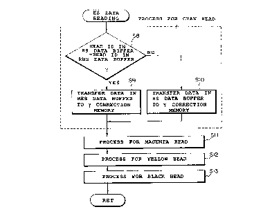
the procedure of reading of the HS data illustrated in
Fig. 45;
Fig. 48 is a flow chart illustrating an example of
the procedure of copying operation illustrated in Fig. 45;
Figs. 49A and 49B are flow charts illustrating an
example of the procedure when a door is opened and
illustrating that when the door is shut, respectively;
Fig. 50 is an explanatory diagram illustrating the
test pattern for measuring shading according to the
present embodiment and the read_~ng method thereof;
Fig. 51 is a flow chart illustrating the procedure of
an RHS operation illustrated in Fig. 45;
Fig. 52 is a diagram illustrating relation between
the test pattern and the CCD line sensor in the present
embodiment;
Figs. 53A, 53B, 53C and 53D are schematic views
showing various states of the loading of a recording paper
to a reader, to the recording paper the test pattern of
the present embodiment being recorded;
- 30 -
2
Figs. 54A, 54B, 54C and 54I> are illustrations showing
the states of the reading of the test patterns which
correspond to the loading states of Figs. 53A, 53B, 53C
and 53D and the content of the read density data,
respectively;
Figs. 55A, 55B and 55C are diagrams for explaining
means for detecting any errors from the density data read
by the reader;
Fig. 56 is a flow chart illustrating an example of
the procedures of the error detecting processing in Fig
51;
Fig. 57 is an explanatory diagram illustrating the
assignment of the density data :read by the reader to each
orifice;
Fig. 58 is a schematic diagram illustrating the state
of forming of dots in the test pattern;
Fig. 59 is a diagram illustrating a shift mean value
operation for obtaining the density data of every orifice;
Fig. 60 is a flow chart illustrating a further
example of density ratio operat_Lon processing in Fig. 51;
Figs 61A and 61B are diagrams for explaining the
shift mean value operation illu:>trated in Fig. 60;
Fig. 62 is a block diagram .showing in detail an
example of the construction of t:he control part according
to the present embodiment;
- 31 -
2~'~~~96
Fig. 63 is a block diagram showing in detail an
example of the construction of the control part according
to the present embodiment;
Fig. 64 is a block diagram showing in detail an
example of the construction of the control part according
to the present embodiment;
Fig. 65 is a block diagram showing in detail an
example of the construction of the control part according
to the present embodiment; and
Fig. 66 is a schematic diagram showing an address
selector of a SRAM in each control mode of the control
part .
Embodiments of the present invention will be
explained hereinafter with reference to the drawings.
Embodiment 1
As embodiment 1, an ink-jet type color copy machine
with five kinds of reduction ma<~nification will be
described hereinafter. Fig. 7 is a schematic perspective
view showing a recording part oi_ the color copy machine.
A recording head 34 is a removable head of a
cartridge type with an integrated ink reservoir, which is
movable along a guide bar 35 in an X direction shown in
Fig. 7 by using driving means (not shown). A recording
paper 32 is transported in a Y direction by rotating a
paper feeding roller 31 in a direction of an arrow. The
- 32 -
.. 20'~~JO~
ink is ejected as the recording head 34 moves in the X
direction, thereby, the whole face of the recording paper
can be recorded. At this time, a paper press 33 presses
the recording paper 32 in order to maintain it flat. The
color copy machine of the present embodiment is provided
with four recording heads 34 each corresponding to black,
cyan, magenta and yellow ink.
Fig. 8 is a diagrammatic view showing an orifice
disposed surface of orifices of the recording head 34.
Each of the recording heads 34 is provided with 128
orifices n 1 through n 128. In order to generate thermal
energy for ejecting the ink, an electro-thermal converting
element is provided in a portion communicated in fluid to
each orifice. A pixel is formed by the ink ejected from
each of these orifices. In every one scanning cycle in
which the recording head 34 ejects the ink while it moves
in the X direction shown in Fig. 7 and returns to the
original position, the recording paper 32 is transported
to the extent of recording width for one line, and is
recorded in order.
When it is identically (equal) sizing recording,
namely ordinary recording, all t:he 128 orifices are used,
therefore, the length of paper transportation equals to
the length L corresponding to the 128 orifices. However,
if it is reduction (reduced) recording, the orifices are
used, which is less than 128 from the orifice at the end
of the orifice array shown in Fi.g. 8, therefore, the
- 33 -
20'~~~~~
length of the paper transportation equals to that
corresponding to these orifices. For example, with
respect to 75 percents (o) reduction recording, the
orifices to be used orifices n 1 through n 96 shown in
Fig. 8, and the length of the paper transportation is L X
0.75.
Referring to the flow chart. shown in Fig. 9, a
shading correcting mode will be explained as an example in
which the 755 reduction recording is compared with the
identically sizing recording.
First, when it is in a shading correction mode, in
step 551, a test pattern is recorded by the recording part
of Fig. 7.
This test pattern is recorded with a constant gray
level (density) of each color as shown in Fig. 10, wherein
a reference numeral 61 designates a recording paper, and
62 a recording area. As described above, when the shading
of each orifice is corrected by reading the sample in the
test pattern, the recording of t;he test pattern by the
endmost orifice must be made under the same condition as
other orifices, taking into con:>ideration the effect of
next orifices on both sides. That is, in the ordinary
recording, a pixel recorded by t:he orifice n 128 should be
positioned in front of a pixel by the orifice n 1, and the
pixel recorded by the orifice n 1 should be positioned
next to the pixel by the orifice n 128. While in the 755
reduction recording, a pixel recorded by the orifice n 96
- 34 -
2~'~559~
should be positioned in front of a pixel by the orifice n
1, and the pixel by the orifice n 1 should be positioned
next to the pixel by the orifice n 96. Figs. 11A and 11B
show in detail the above-mentioned matter, in which in
order to record the test pattern, it is necessary to scan
three times.
In the above recording of the test pattern, the test
pattern of the reduction recording occupies a recording
area smaller than that of the ordinary recording.
Further, in the pattern recording shown in Figs. 11A and
11B, several pixels are respectively recorded next to the
respective side pixels recorded by orifices at a both end
portions, thereby the effect of the secondary reflection
can be prevented, which is derived from a ground of the
surface of the recording paper when the test pattern is
read out. It is, therefore, possible to allow shading
correction conditions of the orifices at the end portions
to approach closer to those of other orifices.
Next, the test pattern is read out in step 552.
In the present embodiment, a chart which the test
pattern is recorded is put on an original (manuscript)
stand and read out in the same manner as the read-out in
the ordinary operation of the copy machine. At this time,
the test pattern should be positioned such that the
direction of a recording scanning of the test pattern may
be at right angles to that of a reading scanning of a
reading head. In this embodiment, the scanning direction
- 35 -
20'~~~06
of the reading head is the direction designated arrow Y in
Fig. 10. Thereby, equalized can be the variation of read-
out characteristic of each sensor in the recording head.
Figs. 12A and 12B show gray level (density)
distribution which was read out during one scanning of the
reading head (sensor). Fig. 12A shows the density
distribution of the identically sizing recording, and Fig.
12B that of the 75o reduction recording. Fig. 12A further
shows the shading made by the orifices n 1 through n 128,
and Fig. 12B further shows that made by the orifices n 1
through n 96. The shading data on one color is obtained
by one scanning of the reading head, the test pattern is
then scanned as the reading head moves to an X direction
shown in Fig. 10, and the test pattern with a next color
is read out. When the shading data is obtained with
respect to four colors, the read-out of the test pattern
is completed.
Next, in a correcting operation of step 53, the
shading data read out as mentioned above is divided into
recording areas and non-recording areas. That is, as
shown by dotted lines in Fig. 12, areas above the dotted
lines each of which means a threshold level fixed to a
certain absolute gray level are set to the recording areas
and other areas the non-recording areas. Next, the
central position of the recording area is obtained from a
step-up position and a step-down position of the recording
area distinguished in the above manner. The central
- 36 -
24?'~~~~
position is set to that of the orifices used in the
recording. In the present embodiment, the position
between an orifice n 64 and an orifice n 65 and the
position between an orifice n 48 and n 49 are determined
as the central position in identically sizing recording
and 75~ reduction recording, respectively. The
correspondence between each orifice and the reading
density data is taken on the basis of the central
position. Next, the ratio of the density data assigned to
each orifice to the average density is calculated. The
correcting operation of step 53 is in detail explained
below.
Now, the density of each of the orifices from n 1 to
n 128 in the identically sizing recording is set to as Dn
(i), where i - 1 through 128, and that in the 750
reduction recording is set to as Ds (i), where i - 1
through 96. After that, the ca_Lculation which uses those
density is performed on the basis of a flow chart shown in
Fig. 13. First, in step 591, when in an identically
sizing recording mode, the average density is calculated
about all the orifices, 128 orifices, and when in a 75~
reduction recording mode, that is calculated about 96
orifices from n 1 to n 96. Next:, a correction ratio of
each orifice is calculated in step S92, where the
correction ratio is a reciprocal_ of the ratio of its
density to the average density. In other words, the
correction ratio means how much correction is required to
_ 37 _.
20'~~~96
its orifice. The value of the correction ratio becomes
lower as the density becomes higher. Next, the processing
is returned to the calculation of the average value in
step 591, because the recording areas of the test pattern
are four about every color as shown in Fig. 10 and in
Figs. 12A and 12B and it is necessary to perform one by
one the calculation processing. Due to the processing
like this, the number of the density data to be read is
increased and as a result, the reliability of the
correction is increased. In addition, the reading errors
of the density is decreased, which is produced by putting
the test pattern on a slant against the reading sensor.
As described above, in steps 59:1 and 592, four units of
the correction ratio are obtainf=d to each orifice. Next,
in step 593, these correction ratio are averaged and the
final correction ratio is obtained. Next, in step 594,
the optimum correction table for each orifice is selected
from among predetermined 64 correction tables on the basis
of the final correction ratio.
Where, the correction table is provided for
determining the relation between the recording duty of an
input signal and that of an output signal. The number of
pixels (dots) to be recorded to the predetermined area is
increased or decreased according to the density by using
this correction table. Accordingly, if the correction
table is suitably selected on th.e basis of the above
correction ratio, the duty of th.e orifice of which density
- 38 -
207~~96
is higher than the average density is reduced by the duty
correction, and the number of the dots to be recorded is
decreased. On the other hand, in the orifices of which
the recording density is relatively low, the reverse is
performed. The present embodiment includes 64 correction
tables, in which the No. 32 table does not give any
correction to the input signal, and 64 tables are set at
equal interval of to correction ratio around the No. 32
table centered. The numbers, 1, 2, ~~~ 64, are given in
order from the first table with the smallest slope. These
number are selected in a table lVo. selection processing of
step S94 shown in Fig. 13.
This selection processing will be concretely
explained. First, the value subtracted 1 from the
correction ratio Pn (or Ps) is that which represents
increase or decrease in the output signal to the input
signal by using plus sign (+) and minus sign (-) and its
magnitude. The value multiplied the above value by 100
represents a direction and a di:>tance from the center of
the table which is set every lg. The final table number
of the orifice is selected by adding the central table
number, 32 to this value. As described above, after the
128 table numbers corresponding to the 128 orifices are
obtained in the identically sizing recording, and
similarly, after the 96 table numbers are obtained in the
reduction recording, the correction operation in step S53
- 39 -
20'~~~9~
of Fig. 9 is completed, and then, the processing transfers
to the next step 554, or memorization step.
A memory for the correction table number is renewed
every correction. However, when the recording with
different magnification is made, like the present
embodiments, the table number data is stored in different
areas according to the magnification without erasing the
memory. That is, there is provided memories corresponding
to the number of the reduction magnification, and the
table data is read out of the si~orage memory which is
corresponding to the recording magnification.
Fig. 15 shows the control construction for the
shading correction processing arid a series of recording of
the test pattern as explained above.
In Fig. 15, a reference numeral 125 designates a
recording sensor, 121 image pro<:essing circuit for
performing a series of image processing when a copy
machine is effectively used for masking, edge enhancement
and so on, 113 a read only memory (ROM) in which the 64
correction tables shown in Fig. 14 are written, 114 a
binarizing circuit for performing binarizing processing
when the recording is made, 115 a central processing unit
(CPU) for carrying out the processing of the whole copy
machine, such as the correction operation in the shading
correction mode, reference numerals 116 through 119 each
designates a random access memory (RAM) in which the table
number data is written corresponding to each
- 40 -
2p'~5~96
magnification. There are provided only three reduction
correction table in this embodiment, however, any
reduction magnification may be performed by combination of
the orifices less than 128.
When the test pattern of a reduction recording is
recorded, the driving data of the orifices n 1 through n
96 in the recording head 34 are switched "on" and the
orifices n 97 through n 128 switched off. In addition,
the rotation of a transporting ~°oller 31 is controlled by
the CPU 115 through a transport_Lng roller driving part
31A, thereby the recording paper is transported by a
distance that corresponds to the length of the orifice
array from n 1 to n 96. It is t=herefore possible to
record the test pattern of the reduction recording.
In the shading correction processing, the density
data of the test pattern obtainE~d by the reading sensor
125 is sent to the CPU 115. After step S53 of Fig. 9 is
performed, the data are written into the RAM of its
magnification mode. At this tune, the original data
written in the RAM are renewed.
When usually used as the copy machine, the manuscript
data which is read by the reading sensor is transformed
into a signal by using the correction tables of the ROM
113 corresponding to the orificE~s respectively when
recording duty of each orifice :is obtained through a
series of the image processing. At this time, the table
number is specified by the RAM :in which the table number
- 41 --
20'~~~96
of each orifice is written in accordance with the
reduction magnification. As described above, excellent
images without the shading can be always recorded in the
various magnification, by providing the density shading
correction mode to every reduct_~on magnification and
storing those correction data in different areas to one
another.
The above embodiment 1 was explained about the ink
jet type apparatus with the recording head, but the
present invention is not limited to such an application
and may be applied to other apparatus such as the thermal
type apparatus with the recording head.
EMBODIMENT 2
Fig. 16 is a sectional side view of the color copy
machine using the ink jet recording apparatus according to
embodiment 2 of the present invention.
This color copy machine is mainly provided with an
image reading and image process_Lng part (hereinafter, both
parts are referred to as a reader part 224) and printer
part 244. The reader part 224 :>cans and reads the
manuscript 202 put on a manuscr_Lpt glass 201 by using a
CCD line sensor 205 including three color filters, or R
(red), G (green) and B (blue). The read data performed a
predetermined processing by the image processing circuit
is set as the recording data to be used in the printer
part 244. In the printer part 244, the image is recorded
- 42 --
20'5596
on the recording paper by using four recording heads
respectively corresponding to the four ink colors, a cyan
(C) , a magenta (M) , a yellow (Y) and a black (B) on the
basis of the recording data.
Hereinafter, the operation of the copy machine will
be described in detail.
The reader portion 224 is composed of member or
elements 201 through 223, and the printer part 244 members
or elements 225 through 243. In this construction, the
left and upper side of Fig. 16 corresponds to the front of
the machine.
The printer part 244 is provided with four ink jet
recording heads 232 which eject ink and make recording, in
each of which 128 ink orifices a re arranged in a vertical
direction (or in a sub-scanning direction and in the right
and the left directions of Fig. 16) at a pitch of 63.5 Vim.
Whereby, the recording with 8.128 mm width can be made by
one main scanning. When recorded on the recording paper,
repeated is the operation including the steps of; stopping
transporting (paper transportation) the recording paper,
carrying out the main scanning of the recording head,
making the recording with 8.128 mm width, transporting the
recording paper by 8.128 mm lone, and making the recording
with 8.128 mm width.
In the construction of the present embodiment, the
main scanning direction of the recording head corresponds
to the direction perpendicular t:o the surface of Fig. 16,
- 43 --
2~'~~~96
and the sub-scanning direction uts right and its left
directions.
Also in the reader part 224, the reading of the
manuscript 202 with 8.128 mm width is repeated in
correspondence with the printer part 244. The moving
direction for read-out of the reading head is called as
the main scanning direction, the direction in which the
reading head moves to the next reading line is called as
the sub-scanning direction. In this embodiment, the main
scanning direction is the right and the left direction of
Fig. 16, the sub-scanning direction is the direction
perpendicular to the surface of Fig. 16.
The operation of the reader part 224 will be
explained below.
The manuscript on the glass of the manuscript stand
is read out in order by the main scanning and sub-scanning
of the reading head. That is, t:he reading head comprising
of lens arrays 204 and light re<:eiving elements 205 is
provided on a main scanning carriage 7. The manuscript
202 is emitted by a lamp 203, tree light reflected from the
manuscript 202 is incident to the light receiving element
205 (CCD) through the lens arrays 204. The main carriage
207 engages to the main scanning rail 208 mounted on a
sub-scanning unit 209 and is slidable to the rail 208.
Further, the main scanning carriage 207 is connected to a
main scanning belt 217 by an engagement member (not
shown), and can move in the right and the left direction
- 44 --
207596
on the surface of Fig. 16 by the rotation of the main
scanning motor. As the main scanning carriage moves, the
lamp 203 emits the light to the manuscript and the main
scanning for read-out is carried out.
The sub-scanning unit 209 engages to a sub-scanning
rail 211 fixed to an optical frame and is slidable to the
rail 211. Further the sub-scanning unit 209 is connected
to a sub-scanning belt 218, therefore, the sub-scanning
operation can be performed by tree rotation of a sub-
scanning motor 219.
The read-out data of an electric signal into which
the light received by the CCD 205 is sent through a loop-
like signal cable 213 to the printer part 244. That is,
one of the end portions of the signal cable 213 is held in
its neighborhood by a holding portion 214, and the other
is fixed to a bottom surface 220 of the sub-scanning unit
209 by a member 221 and is bonded to a sub-scanning signal
cable 223 connected to an electric control unit 226 of the
printer part 244. The signal cable 213 follows the
movement of the main carriage 209, and the sub-scanning
signal cable 223 follows the movement of the sub-scanning
unit 209.
The operation of the printer part 244 will be
explained below.
The recording papers are transported from a recording
paper cassette 225 one by one through a feeding paper
roller 227 driven by a power source (not shown). On the
- 45 --
20'~~~~~
paper, image is recorded by the main scanning of four
recording heads 232 corresponding to four kinds of ink.
The four heads 232 are arranged in the main scanning
direction. Therefore, only one of the heads is shown in
Fig. 16. Each recording head is integrated with an ink
reservoir 233 and is mounted releasably on a carriage 234.
These recording heads 232 are provided with the electro-
thermal converting elements in t;he ink path connected to
each of the orifices, and bubbles are produced in the ink
by the thermal energy generated by the electro-thermal
converting element. The ink is ejected substantially at
the same time the bubbles are produced. The carriage 234
is engaged slidably to a main s<:anning rail 235 of the
printer. The carriage 234 is connected to a main scanning
belt 236 by an engagement member (not shown), thereby the
main scanning can be carried out: through the rotation of a
main scanning motor 237.
The carriage 234 is provided with an arm portion 238
to which one end of a printer signal cable 239 for sending
signals such as a driving signal to the recording head 232
is connected. The other end of the printer signal cable
239 is fixed to a mid-board 240 of the printer by a member
241, and is connected to the elE'Ctric component unit 226.
The line of the printer signal cable 239 follows the
movement of the carriage 234, but it is arranged not so as
to contact with the upper optical frame 210.
- 46 --
20'~5~9~
The sub-scanning of the printer part 244 is performed
by rotating one pair of rollers 228 and 229 and the other
pair of rollers 230 and 231 by a power source (not shown),
and transporting the paper by 128 mm long. A reference
numeral 242 designates a bottom board 245 of the printer
part 244, 245 an outside board, 246 a manuscript press
board, 247 a paper discharging gray, and 248 an electric
component of an operational port: ion.
The fundamental factor of the production of the
shading will be explained again.,
Fig. 17A is a schematic enlargement diagram of the
state recorded by an ideal recoi_-ding head 232. A
reference numeral 261 designate:> orifices for ejecting the
ink. When recording is performE:d by using the recording
head 232, ink dots 260 with identical diameter is formed
on the recording paper. In such a case, the shading is
not produced. Such the case that from all the orifices
ink is ejected was described hereinbefore. However, it
should be understood that the shading may not be produced
also in a half-tone recording such as the recording at
using 50 $ of orifices.
On the other hand, in the case of Fig. 17B, the
diameters of dots 262 and 263 formed by the second and the
(n-2)th orifices are less than t:he average diameter, and
dots formed by the (n-2)th and (n-1)th orifices are out of
the center. That is, the (n-2)t:h dot 263 is formed in the
right and the upper direction of. the center, and the (n-
- 4 7 _.
20'~~~96
1)th dot 264 is formed in the left and the lower
direction.
As a result of these recording, an A area shown in
Fig. 17B appears as a light band, and a B area also
appears as a substantial band lighter than other areas,
because the distance between the center of the (n-1)th dot
and that of the (n-2)th dot become longer than the average
distance eo between the dots. On the other hand, the
distance between the center of t:he (n-1) th dot and that of
the n-th dot is shorter than the average distance eo,
therefore, the C area appears as the band darker than
other areas.
As described above, the shading is produced mainly
due to the variation of the dot diameters and that of the
difference from its central position.
The shading correction processing of the printer
described above will be explained below.
As described hereinbefore, 'the shading is produced
mainly due to two kinds of causes, (1) the variation of
the shape of the orifices or thE: ink path, and/or the
variation of the thermal characteristic of the electro-
thermal converting elements, which are produced in the
course of the manufacturing process, and (2) the variation
of the characteristic of ejection which is produced by
performing a recording operation, in other words, the
variation of the characteristic of ejection which is
produced as time passes. The variation of the
_ 4g _.
__. 20'~~a9s
characteristic of ejection which is produced in the course
of the manufacturing process, c<~n be corrected by a
shipping inspection. However, it is difficult to take a
countermeasure against the variation due to time-passing.
It is considered that the variation due to the time-
passing is caused by the variat_Lon of deterioration of the
orifices, the change in a water head pressure, the
invasion of foreign substances unto the orifice, etc.
However, the true cause is not ~:nown yet in detail.
As to such the shading produced mainly due to the
time-passing, the apparatus itself detects the shading and
resets a new correction curve, as described above.
Fig. 18 is a block diagram showing the process of the
image processing in which the shading correction
processing according to the pre:>ent embodiment is
performed.
In Fig. 18, the reading data read out by the CCD 205
is amplified by an amplifier 2200, and transformed into 8-
bit digital image signal by an A/D converter 2201. A
reference voltages RT and RB of the A/D converter 2201 can
be set by using a microcomputer (not shown). For example,
as shown in Fig. 19, it is possible to extend the
transform of a very small value of an input voltage into
8-bit value by changing the reference voltages RT and RB
to RT' and RB', respectively.
The image signal converted by the A/D converter is
corrected against a white signa7_ by a white correction
- 49 --
20'~~~9fi
circuit 2202, and is corrected against a black signal by a
black correction circuit 2203.
The corrected signal is transformed from the three
primary colors of light, R(red),. G(green) and B(blue) into
that of recording colors C(cyan), M(magenta) and Y(yellow)
by a LOG conversion circuit 2204. The Bk (black) portion
of the C, M and Y signals is extracted as the common
component, or a portion of the <:ommon component of those
signals is extracted as a portion of black component. The
extracted signal is input to a head shading circuit 2206
as C, M, Y and Bk signals.
In the head shading circuit 2206, 'y-correction
(shading correction) is made to the image signal
corresponding to each orifice according to the ejection
characteristic of each orifice of each of the four
recording heads. The head shad9_ng circuit 2206 is
comprised of a SRAM and an EPROM as described below. On
the basis of the orifice corresponding to the data which
is input to the SRAM, the table number to be stored in the
SRAM is referred. Next, the data is corrected by using a
'~-correction curve which stored in the EPROM and
corresponds to the table number. A 'y-conversion circuit
2207 has a plurality of function to calculate output data
to the input data of the conver:~ion circuit, and set the
function suitable to the color gone which users like and
to density balance of each recording color. Further, the
- 50 -
20'~~~96
function is set according to the characteristic of the
recording paper and that of the ink to be used, too.
The output of the y-conversion circuit 2207 is sent to
a binarization circuit 2208. In the present embodiment, a
mean density reservation method (MD method) is used for
the binarizing processing. The output of the binarizing
circuit 2208 is sent the recording head driving circuit
232A of the printer part 244, and the recording is made by
the recording head 232 on the basis of the output data.
Referring again to Fig. 18, a reference numeral 2209
designates a density shading measuring circuit in which
the gray level data (density data) of each orifice is
calculated on the basis of the data from the LOG
conversion circuit 2204. Fig. 20 shows in detail the head
shading circuit 2206 and the shading measuring circuit
2209, and Fig. 21 shows an example of the concrete circuit
realizing the blocks shown in Fig. 20. That is, a RAM
2152 shown in Fig. 21 owns jointly a temporary hold memory
2134 and y-correction memory 21:36 both shown in Fig. 20.
The 64 kinds of y-correction curve shown in Fig. 22 are
stored in an EPROM 2126. An operational circuit 2135
shown in Fig. 20 is comprising of a CPU 2151 shown in Fig.
21.
Fig. 23 is a flow chart of the shading correction
processing according to the present embodiment.
For example, when the user finds the production of
the shading on the recorded picture image, the user pushes
- 51 -
... 20'~~~96
down the button for the shading correction provided in the
operation portion (not shown) (step S1). In response to
the action, the printer part 244 outputs the pattern shown
in Fig. 24 for the shading measurement as a printed matter
(step S2).
Next, the user puts this recorded sample of the test
pattern on the manuscript stand with the main scanning
direction of the CCD 205 being perpendicular to the moving
direction of the recording head with respect to the
recorded sample as shown in Fig. 24 (step S3). And then
the user pushes down again the correction button (step
S4 ) .
In response to this operation, the CPU sets the
reference voltage of the A/D co:nverter corresponding to
its reading color (step S5). That is, if the A/D
conversion is carried out at th~~ reference voltage of the
A/D converter 2201 in the ordinary read-out, namely at a
constant reference voltage, the gray level of the read
data is different depending on -the recorded color even if
the patterns recorded with the name density is read out,
as shown in Fig. 25. If the extent of the shading (the
width of the gray level change) of each recorded color
equals to one another, with respect to, for example,
yellow, the extent of the shading is read out in the state
of shading smaller than that of other colors, because the
level of the density of the read data is relatively low.
Therefore, in such a construction that the correction is
- 5 2 --
29'~5~96
made by using the same algorithm for the shading as the
different color, the extent of the correction of yellow
becomes smaller. As a result, the shading is not
eliminated, therefore, the shading of yellow becomes
remarkable in the image to be recorded having combination
color of yellow and other colors.
According to the present embodiment, the read image
in which the extent of the shading is equal to any
recorded colors is obtained by changing the reference
voltage of the A/D converter 2201 in accordance with the
recorded color (see Fig. 25B). As the result, it is
possible to use the identical algorithm to each of the
recorded colors, and simplify the construction for the
shading correction processing.
After setting the above reference voltage, the
correction of the shading of the CCD 205 is made as
follows (1) reading out by the CCD in the state of light-
off, (2) setting the value of t:he black correction such
that the value of each pixel ma_y be equal to the black
level, (3) carrying out the main scanning, after setting
white board in the state of light-on, and (4) read out the
black test pattern by scanning o f the CCD 205 (step S7).
Next, in similar manner, the above process is performed in
order with respect to cyan, magf~nta, and yellow.
The read result is stored in a SRAM 2136 (step S8)
after it was processed in each of the circuits 2200
through 2204 and in the shading measurement circuit 2209.
- 53 --
2~,~~~~
That is, in step S8, the average of the number of the
sampling of the read data corresponding to each orifice is
obtained by using the circuits 2131 through 2135 shown in
Fig. 20.
Next, a shift mean value Dn of three pixels is
calculated every orifice (step S9), which includes one
pixel before and behind the read pixel corresponding to
each element of the CCD 205. It is appreciated that the
average of the total 9 pixels may be used as the shift
mean value of this case, and the weighted pixels may be
used. After the calculation of the shift mean values, the
average value of all of the shift mean value Dn obtained
in step S9 is calculated (step S10) . The ratio Ocn (~) of
the value obtained in step S10 to the average value
obtained in step S9 is calculated, where n is an orifice
number between 1 and 128. The above processing from step
S9 to step S11 is performed on 'the test patterns 1 through
4 shown in Fig. 24 (step S12).
Next, the average value Ocn (ave) of the value Ocn in
each pattern is obtained (step S13), and a new correction
table number Ti+1 is obtained from the Ocn (ave) and a
present correction table number Ti as follows (step S14),
Ti+1 (n) - Ti (n) + (pin (ave) - 100) (1)
The newly obtained table number Ti+1(n) is written in a
SRAM 2136 (step S15) .
The above processing from step S5 to step S15 is
performed to each color (step S:L6) .
- 5 4 --
207~~9~
When the test pattern is read out, the output of the
filter of green, red, green and blue are sampled to the
patterns of black, cyan, magenta and yellow, respectively,
where the former colors are they complementary colors of
the latter, respectively. It is possible to use another
color except green, instead of black.
As it is clear from the above description, in the
present embodiment, the table data of the SRAM 2136 is
renewed by the above processing to prevent the production
of the shading due to the time-passing.
At this time, in order that: the renewed data is
stored even at power-off, the shading data is transferred
to a RAM backed up by a battery (not shown) in the printer
control portion.
In the above embodiment, th~.e reference voltage of the
A/D converter is set according t o the ink color by using
the CPU before reading out the 'test pattern. However, it
may be possible that pattern is read at a normal reference
voltage, the variation of the read data and the density at
the time is detected, and the test pattern is read out
again after setting the reference voltage on the basis of
the detected result.
Embodimen 2A
In the above embodiment 2, t he gray (density) level
of the read data becomes equal between recorded colors by
setting the reference voltage of_ the A/D converter
- 55 --
24'~~~~6
according to each of the recorded colors. Accordingly,
the actual shading is reflected equally to the read data
of each recorded color.
On the other hand, in the present embodiment, the
density level of the read data becomes equal by making a
black correction according to the recorded colors in the
black correction circuit shown in Fig. 18.
Embodiment 2A of the present invention will be
explained below.
Figs. 26A, 26B and 26C are graphs illustrating the
black correction according to the present embodiment.
When the CCDs 205 read out a jet-black manuscript,
not all of light receiving elements outputs the "0" level
due to the variation produced in the course of the
manufacturing process of each element. It is necessary to
sample the black value read (in this embodiment, sampling
during light-off) and store it in a memory, in which the
black value is obtained by reading a black shading
correction board painted jet-bl<~ck, or by reading the
manuscript after lighting off an illumination lamp for it.
In the ordinary recording, the black correction is
made by subtracting the stored black read-out value from
the read-out data of the manuscript, and by multiplying
the subtracted value by the corx:ection value. That is, by
subtracting the black data (solid line) shown in Fig. 26B
which was previously sampled from the read-out data shown
- 56 -
2~~~~96
in Fig. 26A, data (solid line) shown in Fig. 26C are
obtained.
If the black correction dat a with relatively high
brightness as shown in dotted line of Fig. 26B is obtained
by sampling the shading board which is not jet-black, it
is possible to reduce the brightness of the input data
(increase the density) as shown at the dotted line of Fig.
26C when it is made the black correction.
As described in the above embodiment 2, when the
density level decreased like yellow, it is possible to
equalize the density level of the read-out data of each
recorded color by using the data with relatively high
brightness as the stored data (sampling data) in the black
correction of yellow (Y).
Fig. 27 is a flow chart of the shading correction
processing according to the present embodiment. In this
processing, only step 5105 is different from the
processing of embodiment 2 shown in Fig. 23. Therefore,
only the processing of step 5105 will be explained, and
the description of the processing of other steps is
omitted.
In step 5105, the black data are sampled by reading
out the black shading board corresponding to the recorded
color to be read out at the time. That is, as usual, for
example, when the data obtained by sampling after light-
off is used in common as the black data of each recorded
color, the density level of the read-out data is different
- 5 7 _.
207~~96
according to the recorded color. even if the pattern
recorded by the ink with identical density is read out as
shown in Fig. 25A, as explained in embodiment 2. For
example, in the case of yellow (Y), the extent of the
shading is rad out in the state of shading smaller than
that of other colors, because the level of the density of
the read-out data is relatively low. Therefore, in such a
construction that the correction is made by using the same
algorithm for the shading as the different color, the
extent of the correction of yellow becomes smaller. As a
result, the shading of yellow becomes remarkable in the
image to be recorded having the combination color of
yellow and other colors.
According to the present err.bodiment, the density
level is increased according to each recorded color in the
black correction processing, therefore, the actual shading
is equally reflected to the den;;ity level after the block
correction in each recorded color. Accordingly, the black
shading board for sampling the black data is different
according to the recorded color, thereby, the following
shading correcting to other recorded colors can be made in
a similar manner.
It should be understood than the actual board is not
used as the black shading board for each recorded color of
the present embodiment. In the present embodiment, the
black correction colors for each color are painted out the
side surface of the white shading correction portion in
- 58 -
2~~~~9~
the operation area of the CCD which is outside of the
manuscriptglass, and the CCD samples after moving down to
the portion where the necessary color is painted. The
sampling method is well-known to a person skilled in the
art, therefore, the detailed description will be omitted.
In the above embodiment, tree copy machine provided
with the manuscript read-out device has been explained as
an example. However, it will be apparent that the present
invention may be applied to a recording apparatus which
records with a plurality of colors and can read out the
recorded test pattern.
Further, the recording apparatus of the ink jet tape
has been explained hereinabove. However, the present
invention is applicable to a recording apparatus of the
thermal transfer type. That is,, it should be understood
that the present invention is applicable to any apparatus
which has a plurality of recording elements and records
with a plurality of colors.
Embod~m n
In this embodiment, the application of the present
invention to the apparatus similar to the copy machine of
embodiment 2 shown in Fig. 16 will be explained.
Accordingly, like reference numerals identify similar
elements of which the detailed description is omitted.
Fig. 28 is a diagrammatic vuew showing in detail a
CCD line sensor 205 of the present embodiment. This line
- 59 -
sensor is provided with a line of 498 light receiving
cells. Three cells, R,G and B correspond to one pixel
(hereinafter, referred these three cells to as one pixel
cell). Therefore, 166 pixel are substantially read out by
the 498 light receiving cells. The number of effective
pixel cells is 144, and the pixel width of these 144 pixel
cells is about 9 mm.
Fig. 29 is a perspective view showing the external
appearance of an ink jet cartridge in the printer part 244
of the color copy machine of the present embodiment. And,
Fig. 30 shows the details of a ~orint board 285 of Fig. 29.
Referring to Fig 30, a reference numeral 851
designates a print substrate, 852 an aluminum radiator
plate, 853 heater board compressed of a heater element and
a diode matrix, 854 memory mean;; for preliminarily storing
the density shading information,. a non-volatile memory
such as EEPROM, and other memorues, 855 a contact
electrode which forms a joint portion to a body. A line
of orifices are not shown here.
As shown in Fig. 30, the EE)?ROM 854 in which shading
data of respective recording heads are to be stored is
equipped on the print substrate 851 including heater
element of the recording head 232 and drive control part.
The shading data or its correction data to respective
orifice or orifice group, which is set on the basis of
shading measurement data measured with respect to the
respective recording head when produced.
- 60 -
2~7~~5
Thereby, when the recording head 232 is attached to
the main device, the information on the shading is read
out of the recording head 232, and the predetermined
control is performed in order to improve the shading.
Accordingly, it is possible to maintain the improved image
quality.
Figs. 31A and 31B show an example of main circuit
construction on the print substrate 851 shown in Fig. 30,
where the circuit construction in the heater board 853 is
at the inside of a dotted line block. The heater board
853 has NXM matrix structure of a circuit which connected
in serial the heater element to a diode 856 for preventing
a current flowing into. That is, these heater elements
are driving in time sharing every block as shown in Fig.
32, and the supply of the driving energy is controlled by
changing pulse width (T) applied to the segment (Seg)
side.
Fig. 31B shows an example of the EEPROM 854 shown in
Fig. 30. In the EEPROM, the shading information according
to the present invention is stored. This shading
information is transmitted in serial communication to the
main device in response to the demand signal (address
signal) from the main device.
Fig. 33 is a diagrammatic view showing the relation
between the diameter of an ink drop to be ejected and
driving energy applied to a heating element 853 of the
orifice of the recording head 2~~2. As understood from the
- 61 -
characteristic curve of Fig. 33, the diameter of the ink
drop is increased as the energy is increased within a
certain range of the driving energy. The increase in the
diameter stops when the driving energy deviates from the
range. However, it is to be understood that the diameter
of the ink drop between a larger orifice and a smaller
orifice is greatly different in the same driving energy.
Referring to Fig. 33, in order substantially to match
the diameter the ink drops between orifices with different
diameters, for example, in order to control the diameter
of the ink drop to the identical value eo, driving energy
E2 is supplied to the smaller orifice, while driving
energy E1 (E2 > E1) is supplied to the larger orifice. In
such a manner, the suitable driving energy is determined
according to the magnitude of tJze actual diameter of the
ink drop, and the value of its driving energy, or the
discrimination information corresponding to the driving
energy is written in the non-volatile memory (EEPROM) 854
shown in Fig. 30. Thereby, only the shading due to the
difference in the ink drop diameter between the orifices
can be eliminated.
In addition, when the variable control of the driving
energy of the respective orifice increases the scale of
the circuit, for example, in the case that matrix-drive
recording head as shown in Fig. 31A is used, each block is
set to a minimum unit, the average value of the ink drop
diameter of orifices in the block of minimum unit may be
- 62 -
2~7~~~~
calculated, and the driving energy based on the average
value is written in the non-volatile memory 854 in a
manner similar to the above embodiment. Accordingly, it
is possible to control the shading every block unit,
thereby, the circuit is simplified. As the discrimination
information described above, it is possible to use control
pulse width, a driving voltage, a driving current and so
on.
Next the countermeasure against another cause of the
shading, the difference between the center positions of
recorded dots will be explained below. The shading due to
the cause is mainly reproduced :by the deflection of the
direction of ink-ejection, which is due to the limitation
of accuracy of finishing. Accordingly, it is difficult to
correct the deflection. And hence, in order to reduce the
shading, the image density within a certain area which is
recorded by this recording head is detect before shipping
of its product. The control dai:a based on the detected
value is stored in the non-volatile memory 854, and the
amount (number) of ink ejection to the area is controlled.
For example, in the case that the 50 o half-tone
recording by the ideal recording head as shown in Fig. 34A
and is performed by using the rE:ading head producing the
shading due to the variation of the drop diameter, etc.,
the following processing is performed in order to reduce
the shading. That is, the total. dot area in the area
enclosed with dotted line shown in Fig. 34B is drawn near
- 63 -
207~~96
that in the area shown in Fig. 34A. Thereby, the
recording by the recording head with the characteristic as
shown in Fig. 34B is not distinguishable from that of Fig.
34A.
As to the b area of Fig. 3~1B, by like processing, the
shading is substantially eliminated. The density
correction is controlled by the image processing in Roader
part 24.
For the sake of brief description, the result of
processing of the density correction control is expressed
schematically by using blocks as shown in Fig. 34B,
wherein oc and (3 designate dots for correction. What is
known as a general binarization method for image
processing is a dither method, an error distribution
method, a mean density reservation method and etc. as
these methods are not subject m<~tter of the present
invention, explanation of the method is omitted in the
specification.
The density correction processing of the present
embodiment can be processed as ';~-correction control
processing in the flow of the s_Lgnal processing of reader
part 224 as shown in Fig. 35.
In Fig. 35, an image signal is read from the CCD
sensor 205, one of solid image pick-up element. The
sensibility of the sensor is corrected in the shading
correction circuit 391.
- 64 _.
207~~9~
The corrected signal is tr<~nsformed from the three
primary colors of light, R(red), G(green) and B(blue) into
that of recording color, C(cyan), M(magenta) and Y(yellow)
by LOG conversion circuit 392. The Bk (black) portion of
the C, M and Y signals is extracted as the common
component, or a portion of the common component of those
signal is extracted as a portion of black component. The
extracted signal is input to a head shading circuit 394 as
C, M, Y and Bk signals .
In the head shading circuit. 394, 'y-correction (density
correction) is made to the image signal corresponding to
each orifice according to the ejection characteristic of
each orifice of recording heads. The y-correction data is
supplied to a '~-conversion circuit 395. The y-conversion
circuit 395 has a plurality of functions each of which
corresponds to each step for calculating an output data
out of input data as shown in F:ig. 36, in which the
relation between the input data and the output data can be
selected in accordance with density balance of each color
and color like of user. These functions are also
determined according to characteristics of ink and that of
reading paper. Further, the out: put signal from y-
conversion circuit 395 is sent t:o a binarizing circuit.
In the present embodiment, a mean density reservation
method (MD method) is used for t:he binarizing processing.
The output of the binarizing circuit is sent the printer
part 244, and forms a driving data for the recording head.
- 65 -
2~'~~~9~
In Fig. 35, the head shading circuit (y-correction
circuit) 394 is at the prestage of the y-conversion
circuit 395, and y-conversion is performed after y-
correction. However, the reverse construction is also
effective.
In Fig. 35, a reference numueral 397 designates a
density shading measurement portion. In the present
embodiment, the combination par, 3100 of the head shading
circuit (y-correction circuit) 394 and the shading
measurement portion 397 is simi:Lar in an electrical
construction to that of Fig. 21 in embodiment 2. And the
portion 3100 of Fig. 35 is simi:Lar in a detailed function
to that of Fig. 35 is similar in a detailed function to
that of Fig. 20 in embodiment 2. In addition, detail of
the portion 3100 shown in Fig. 35 is similarly shown in
Fig. 20.
In Fig. 20, the average density data of each orifices
is calculated by an operational portion 2135 (CPU 151),
and the correction tables shown in Fig. 37 are assigned to
each of the orifices. The obtained correction table
number is stored in a RAM 2136 for correction of Fig. 20.
As shown in Fig. 20, a memory 2134 for storing
temporarily the read-out density data and a y-correction
memory are common to a RAM 2152. Fig. 37 illustrates the
inside assignment.
In an EPROM 2126 shown in F:ig. 21, 64 kind of y-
correction curves are stored in the layout of Fig. 38.
- 66 -
207~~96
Next, y-correction processing will be explained
concretely. A Y-correction circuit 394 is provided with
many correction function (in this case, 64 kinds of
function, or #0 to #63). For example, the function #32 is
a direct line at an angle of inclination of 45 degrees, an
input is outputted as it is . In the font-.t-; nn ~f ~.~r; ~.r,
number is less than #31, the input multiplied the input
signal by a constant less than 1 is output. When this
function is caused to correspond to the high density
portion of the recording head, the input image signal is
corrected to lighter density than the actual density,
while in the function of which number is more than #33, by
multiplying the input signal by a constant more than 1,
the input image signal is corrected to darker density than
the actual density. In this ca:>e, therefore, that
correction is effective for the orifices of recording head
32 recording relatively lighter image (pixel).
In addition, this correction table takes any one of
the curves as shown in Fig. 22 according to the running of
ink which depends on the relation between the ink and a
paper and the binarization methc>d, for example, the error
distribution method or the density reserving method.
Generally speaking, the increasing ratio when the
dots are formed on a white sheet is higher than that when
the dots are formal again on the dot which has been
already formal. In higher duty, the shading does not
becomes so remarkable, because the dots is already
- 67 -
207~~~6
superimposed. Accordingly, the correction ratio is the
highest in the neighborhood of half-tone (80H), it become
lower as gaining away from the half-tone. In addition, in
lower duty, it is not necessary to correct, because the
distance between dots is very large. If corrected, the
difference between the ejection orifice and the non-
ejection orifice increase, thereby the band becomes
clearer.
In this embodiment, a function of a plurality of
characteristics corresponds to one of the orifices of the
recording heads 232, respective:Ly. That is, the
discrimination number of the correction function
corresponding to respective orifice as shown in Fig. 22 is
stored in advance in the non-vo_Latile memory. By
referring these discrimination number, the image signal is
made a y-correction in the y-correction circuit 394, and
the result of correction is sent. to the binarization
processing circuit 396 through a 'y-conversion circuit 395.
The binarization processing circuit 396 has the function
for converting multiple valued information (8-bit in Fig.
22) into a binary value, "1" or "0", in which the
binarization is performed by using dither method, error
distribution method or average density reserving method as
described previously. In the present embodiment, the
average density reserving method. is adopted, as a binary
output, the output result as shown in Fig. 17A of
embodiment 2 is obtained at the printer part 44.
- 68 -
2o~~~~s
Fig. 40 is a block diagram showing in detail a
circuit construction of the Y-correction circuit 394 shown
in Fig. 35.
In Fig. 40, reference numeral 3120 designates a
counter, and 3121 a decoder. A:ny one of RAMs 3122 through
3125 at the post-stage is selected by output of the
decoder. These RAMs (Random Ac~~ess Memories) store color
conversion data corresponding each color. As shown in
Fig. 20, ~-correction RAM (3122 to 3125) and density data
temporary hold RAM 2134 are co-owned. 2126 y-correction
ROM (Read Only Memory) which stores y-correction table
data shown in Fig. 38.
The color signals T1, T2 supplied from Bk
production/UCR circuit 393 of Fug. 35 are 2-bit signal
each having any one of "00" "O1" "10" and "11", and in
order to discriminate colors, the contents of the above 2-
bit corresponds to Y, M, C, and Bk, respectively. The
counter 3120 to which the lower bit signal T2 of the 2-bit
color signal is input, counts u~> at rising-up of the
signal T2 when the output of they decoder is Bk(CS - EK).
In other words, at the end of c signal, the counter 3120
is added by +1. Because a set of Y, M, C, and Bk means
one pixel information, the counter 3120 is counted up
every pixel unit. The output of the counter 3120 is
applied to address input terminals of four RAM 3122
through 3125.
- 69 -
24'~~~96
The content of a non-volatile memory 854 is
transferred and is written in advance to the RAMs 3122 to
3125 via the CPU 151 (see Fig. 20). The output of the
decoder 3121 designate and gain access the address of the
RAM 3122 through 3125 in order, in synchronization with
the color signals T1 and T2, as a result, the content of
the RAM gained access is output selectively and is input
as the upper address of the y-correction ROM 2126.
That is, the output of the counter 3120 designate the
orifice number of the recording head 232 corresponding to
the image data at that time. The number (#0 to #63 of the
characteristic curve of Fig. 22) of y-correction curve of
the orifice is recorded at the area pointed out the
address which is the orifice number stored in the RAMS
3122 through 3125. Accordingly, the upper address of the
y-correction ROM 2126 points out the table number, and at
its lower address, the image data which is output from the
Bk production/UCR circuit 393 i~: input is it is. The
input image data is corrected according to one function
selected among the ~-correction curves of Fig. 22, and it
sent to a 'y-conversion circuit 395.
Next, the operation of the ~~-conversion circuit at the
varied magnification will be explained.
Fig. 41 shows the relation between the read-out of
the scanner and the recording of the printer in the
reduction mode of the present embodiment. Fig. 41 shows
- 70 -
207~~96
50~ reduction record for the sake of simplification of
description.
In this case, the information obtained by reading the
manuscript by 128 sensors of the CCD 205 is carried out a
thinning out by half, and is recorded by the 64 orifices
of the recording head at the printer part. In the present
embodiment, as shown in the same drawing, the printer part
makes a recording by using a lsi~ orifice to a 65th orifice
(a first group) in a first scanning of the CCD 205, and by
using a 65th orifice to a 128th orifice (a second group)
in a second scanning of the CCD 205. In a similar manner,
the printer part makes a recording by using the first
group in a third scanning, and by using the second group
in a fourth scanning. That is, in the reduction mode, the
recording head is used half by half. Therefore, in the
printer part 44, the recording sheet is transported every
8.128mm long even in the reduction mode, where the main
scanning carriage 234 of the printer scans twice the same
region (8.128mm width) of the recording sheet. As seen
from the above description, since in the reduction mode,
the orifices to be used are alternately changed, the
initial value of the counter 3120 in Fig. 40 is determined
to be "0" in case of recording with the first group, and
its initial value is determined to be "64" in case of
recording with the second group, which is performed by CPU
2135 shown in Fig. 20. CCD 205 has 166 sensor elements.
In case of an image processing f>y such a band processing
_ ~l _.
20'~~~96
as in this embodiment shown in :E'ig. 43, in an algorithm
for the binary process, it is required to perform a
connection processing between adjacent bands, the scan n
and the scan (n + 1). In order to do so, the image
processing part of the scanner part actually image
processing over 128 + 06 pixels in an individual band.
Such image processing includes procedures performed in the
head shading circuit 394 in Fig. 38.
What is shown in Fig. 42 is a content of data stored
in the storage area for HS data (density correction table
numbers) in RAM 2152 in Figs. 20 and 37 of this
embodiment. HS data corresponding to orifices from 1 to
128 are stored in the address a~__°ea starting from 1800H,
and from 1880H, HS data corresponding to orifices from 1
to 128 are also stored. This i:> because HS data should be
stored redundantly in order to cope with the connection
processing between adjacent bands as shown in the right
side of Fig. 42, in which HS data storage is determined on
the bases that which orifices are used for recording a
connection part shown by dotted arrows in the next main-
scan displacement of the carriage 234.
As described in Fig. 41, in this embodiment, in
recording operation, as the fir~;t group and the second
group are selected alternately, a single set of table
structure for HS data is eventually sufficient for both
cases of reduction recording and magnification recording,
which can be realized by modifying the access region as
_ 72 _
20'~~~96
shown in the right side of Fig. 41. However, in case of
only 64 orifices included in the first group, HS data
table in RAM 2152 is reformed b;y storing HS data
corresponding to orifices form 1 to 64 into the address
are starting from 1840H. Therefore, in this case, it may
be allowed that HS data area in RAM 2152 is selectively
used as shown in Fig. 42 and 43 in responsive to the
magnification ratio. In this case, a memory area is
prepared for storing temporaril:~ contents of data shown in
Fig. 42 and 43. In addition, even in case of recording
with an arbitrary number of ori:Eices continuously adjacent
to one another, it can be possible by modifying HD data in
RAM 2152 in designated values.
In the above embodiment, what is shown is a case
that, a copy machine is constructs ed by connecting an image
reading apparatus and an ink jet: recording apparatus and
that the density correction pro<:ess is performed in the
image reading apparatus itself. The philosophy of the
present invention is not limited within this embodiment
but applicable to an ink jet recording apparatus which
accepts image data in an RGB signal format from color VTR
apparatus as well as applicable to a facsimile. In this
case, the y-correction circuit 394 for correcting the
density shading is formed in the signal processing system
in the ink jet recording apparatus.
Next, by referring to Fig. 44 illustrating an example
of an external structure and shape of an apparatus of this
- 73
20'~~~9~
embodiment, Fig. 45 showing a schematic control flow of
the apparatus of this embodiment, Fig. 46 describing
procedures in step Sl shown in Fig. 45, and also referring
to Figs. 47, 48, 49A and 49B showing procedures in steps
S2, S4, S6 and S7, respectively, an overview of
operational procedures of the apparatus of this
embodiment.
In step S1 in Fig. 45, after the main electric power
switch 1008 in Fig. 44 is turned on, a temperature control
is started for maintaining the izead temperature to be
around 25°C for preparing the recording operation, and
next, data stored in a non-volai~ile memory of the
recording head installed in the apparatus are coped to
SRAM used as an HS buffer together with the head
identification ID. The data sto red in the non-volatile
memory of the recording head in<:lude the head
identification ID specific to the installed recording head
and y-correction table numbers, each corresponding to an
individual orifice of the recording head. Procedures in
step S1 are performed always in case that the recording
head is replaced or exchanged due to user's requirement,
for example, at the time when the electric power supply is
turned on, or the door 1010 in F'ig. 44 formed for service
operations in exchanging the recording head is opened or
closed.
In the SRAM of the printer part, the new HS data
obtained in the latest RHS processing are stored and
- 74 -
2~'~~~9~
backed up by the batteries. The previously described RHS
data buffer are also backed up by the batteries. As the
HS data buffer and the RHS data buffer contain couples of
the head identification ID's and the y-correction table
numbers, each couple corresponding to an individual
orifice of the recording heads. These data buffers are
prepared for an individual recording head, each
corresponding to one of individual ink fluid colors, cyan,
magenta, yellow and black.
Next, in step S2 HS data are transferred to the y-
correction memory, and at the same time, the following
judgment is performed in order to used the latest HS data
of the installed recording head.
If the ID of the recording head for cyan ink color
which is copied at the electric power supply as shown in
step S8 in Fig. 47 is turned on and the ID stored in the
RHS data buffer are identical to each other, HS data to
which RHS processing is applied are used for recording in
step S9 as this comparison resu=Lt means that RHS
processing has been already app7_ied to the recording head
and that the result of RHS processing sill remains in RAM.
As data stored in a non-volatile memory of the recording
head are not revised again, RHS data to which RHS
processing is applied are guaranteed so as to be newer
than the initial HS data of the recording head.
If the ID of the recording head and the ID stored in
the RHS data buffer are not identical to each other, as ID
- 75 -
20'~~~96
data store in the RHS data buffer are specific to another
recording heads, there ID data cannot be applicable to the
currently installed recording head. In this case, ID data
stored in the HS data buffer of the recording head are
transferred to the y-correction memory in step S10. With
respect to another recording heads for magenta, yellow and
black ink colors, steps 511, S12 and S13 including
procedures similar to steps S8, S9 and S10 are applied.
After transferring HS data corresponding to the
currently installed recording head into the 'y-correction
memory, input judgment process for detecting input signals
from keys such as COPY key 1005 used for prompting a
request for a copy operation in step S4 in Fig. 45, which
is a major objective of the apparatus, said keys being
placed on the apparatus operation part 1004 in Fig. 44,
and input signals from a door switch not shown but
installed on the door used for :>ervice operation such as
exchanging the recording head (:>tep S3 in Fig. 45).
In the following, a schematic flow of the copy
operation in step S4 in Fig. 45.
Fig. 48 is an example of procedures for the copy
operation which is started in responsive to the operation
of the COPY key 1005. At first, in step S4-1, what is
judged is whether the recording mode is reduction mode or
magnification mode. In case of reduction mode, step S4-2
is selected next in which, as described with Fig. 42,
recording is performed as changing the access regions so
- 76 -
that HS data (table numbers) corresponding to an
individual group selected in a single scan operation may
be selected. Alternately in step S4-2, as described with
Fig. 43, recording is performed after HS data are revised
so as to correspond to the currently used recording head,
for example, HS data are transformed from those shown in
Fig. 42 into those shown in Fig. 43. On the other hand,
in case of magnification mode, .as described with Fig. 42,
after altering the access regions so that an access region
corresponding to the current recording mode in order to
assure that all the orifices are applied in a single scan
operation, or after converting HS data into those shown in
Fig. 42, recording is performed in step S4-3.
Next step is step S6 in Fig. 45 for processing in
case that the door for service operation of an exchange of
the recording head, which includes procedures shown in
Fig. 49A. When the door is opened, the door switch is
turned off which is detected in step S3, and then
processors in step S6 are executed. As shown in Fig. 49A,
these procedures include a process for shutdown of all the
driving motor in the apparatus i.n step S6-l, a process for
turning off the halogen lump in the read-out system and
shutdown of the electric power supply for driving the
recording head in step S6-2, and. so on. A series of these
procedures are aimed for protecting the user by shutting
down currents in electric circuits and mechanical movement
of components of the apparatus. After the door-open
_ 77 _
20'~~~96
process is performed, input operations by another keys are
prohibited until the door is closed again which is
detected by the turning-on of the door switch in step S3
in Fig. 45, during which the LED display 1007 in Fig. 44
reports an error message in step S6-3 in order to announce
to the user that the door is open.
When the door is closed, th.e door-shut process in
step S7 is executed. By referring to Fig. 49B, if the
door is detected to be closed, 'the head temperature is
controlled to be a designated operational temperature for
preparing the recording operation in step S7-l, and the
LED display stops reporting an error message and displays
ordinary operation conditions such as the number of copies
sheets in step S7-2.
In the apparatus of the present embodiment,
procedures corresponding to keys other than that installed
on the operation part described already are also executed.
These procedures are not mentioned and not described in
detail specifically in Fig. 45, as they are not directly
related to the present invention.
RHS (Reader Head Shading) operation of step S5 in
Fig. 45 is one of the important operations in this
embodiment, that is, a correction processing for shading
using an apparatus read-out system described in
embodiments 1 and 2. In the shading correction
processing, by reading a recorded pattern by the apparatus
read-out system and modifying HS data so as to
_ 78 -
compensating shading, can be corrected shading caused by
aged deterioration of recording heads. This is the end of
explanations of operations schemes of the apparatus of
this embodiment.
In this embodiment, the apparatus itself has a means
for correcting shading caused by aged deterioration of
recording heads. This means th<~t, at the generation
shading, a test pattern shown in Fig. 50 is recorded at
first in an operational procedure to be described later.
This recorded test pattern is read-out by CCD 205 and used
for shading measurement processing.
As shown in Fig. 50, what is prepared on the
manuscript stock is a manuscript: sheet on which a basic
pattern for measuring shading, for example, 50 ~ half-
toned pattern, is formed so that. the direction in which a
one-dimensional array of orifices is defined may be
vertical to the direction in which a one-dimensional array
of CCD line sensor 205. This basic pattern formed on the
manuscript sheet is scanned by t;he CCD line sensor 205.
In the case that the resolution of the recording head 232
is equal to the resolution of the CCD line sensor 205,
pixel density data of pixels they number of which is
corresponding to the number of light receiving elements of
the CCD 205 can be obtained. In the case that the
resolution of CCD 205 is higher than the resolution of the
recording head 232, it is necessary to calculate the pixel
density of a recorded single pixel using pixel density
- 79 -
20'~~~96
data of a plurality of light receiving elements of CCD
205.
An average density of each orifice is calculated
numerically by CPU 2135 and a correction table as shown in
Fig. 22 assigned to each orifice is defined. Each
correction table has its own ID number, which is newly
stored in Y-correction RAM 2136 in Fig. 40 and its
corresponding old correction table is revised. As
described earlier, in this embodiment, RAM 2134 and RAM
2136 are embedded into a single RAM 2152.
Next, a specific control flow of RHS is described by
using Fig. 51. Procedures in the control flow are
categorized into two groups; procedures for recording test
patterns and procedures for reading out the recorded
patterns by the read-out system and for numerical
calculation of HS data.
At first, in responsive to user's operation of
pressing down RHS key 1006 in Fi.g. 44 on the operation
part of the apparatus test patterns are recorded. This
process is performed in step S19 for ejections restoration
action and in step S15, both in Fig.5l. In step 514,
sticky ink fluids are removed from the recording head, air
voids are removed by sucking ink fluids from the orifice
and the head heater is cooled, all of which are performed
sequentially. Procedures in step S14 are preferable as
preparatory actions for establishing good pre-conditions
for recording test patterns used in RHS process.
- 80 -
2~'~~~9~
In step 515, a test pattern shown in Fig. 50 is
recorded. This test pattern contains 16 blocks, each 4
blocks corresponding to an individual ink color which are
recorded in the vertical direction in Fig. 50 with their
pattern density being 50 ~ half-tone. Each block of the
test pattern is recorded in a designated position on the
recording sheet. This recorded position of blocks is
determined so that error detection procedures in the test
pattern read-out process to be described later may be
easily established. Each block is recorded by scanning a
single recording head three times, that is, each block is
composed of three recorded linea. The first and third
lines are formed by ejecting ink fluids from 16 orifices
at the top end part of the recording head and 16 orifices
at the bottom end part of the recording head, which means
that 32 orifices out of overall 128 orifices of the
recording head are used. The second line is formed by
ejecting ink fluids from overal=L 128 orifices of the
recording head. As a result, the width of each half-tone
pattern block is equivalent to :L60 pitches of orifices of
the recording head. The reason why the width of each
pattern block is 160 orifices pitch is described below.
As shown in Fig. 52, in the case of using a recording
head 232 having, for example, 128 orifices, in reading out
of a test recorded by the recording head 232 by the CCD
sensor 205, because the reading out is influenced by the
color of ground of the recording paper, which is, for
g1 _.
20'~5~96
example white, the read-out density data An corresponding
to dots formed by orifices at the top and bottom end parts
of the recording head end to be less than the actual dot
density. Therefore, if each block is formed only by 128
orifices, the reliability of the read-out density data for
the edge part of the recorded block may not be
established. In this embodiment, each block is recorded
by 160 orifices, and by using the read-out density data
which satisfy a certain threshold level as effective and
reliable data and by defining a center orifice as to be an
orifice located at the center of orifices all of which
define effective and reliable read-out density data, a
couple of dot density data at the dot positions apart from
the center orifice by the half of the total number of
orifices, for example, 64 orifices in this case, are
assigned to the lst orifice and the 128th orifice,
respectively.
In addition, the reason why edge dots of each block
are recorded by 16 orifices is t hat the storage area of
RAM 2152 for storing temporarily shading data and that a
test pattern formed repetitivel~T as shown in Fig. 50 may
be scanned by a scanner in case of using such a small-
sized recording apparatus as an A4-size sheet recording
apparatus.
After recording a read-out :pattern, in step S16 in
Fig. 51, whether or not RHS key 1006 is pressed down or
not is judged. The user of the apparatus is expected to
- g 2 _.
2Q~~~~~
set the output sheet on which a. read-out pattern is
recorded on the manuscript stock with the face of the
sheet baing down so that the recorded test pattern may be
scanned and that a set of four blocks recorded with an
identical color ink may be arranged in the direction
identical to the direction in which the CCD sensor 205 is
scanned. At the time when the user presses RHS key 1006,
step S17 in Fig. 51 is selected to be executed next.
Procedures from step S17 tc> step S28 are for reading
out shading data and for calculating HS data. AT first,
in step 517, a shading process of the CCD sensor 205 is
performed by using a reference white board 1002 shown in
Fig. 44, and next, in step 518, a test pattern is read-
out. In step 518, "1 line" means a single scanning action
of the CCD sensor by which a set of four blocks recorded
with an identical color ink are read out at one time. So
far, in step S18, test pattern data of a set of four black
color black is are read out and store. As blocks are
placed on the recording sheet in designated positions so
that shading data may be stored in a designated area in
the memory, the layout of data storage areas in the memory
and the volume of these areas are established as shown in
Fig. 50 in case that shading data are read out properly.
In this embodiment, 1st set of :shading data for one blocks
occupy the data storage are between OOOOH and 01FFH.
Similarly, 2nd to 4th sets of shading data are stored
- g 3 _.
20'~~~~~
between 0200H and 03FFH, between 0400H and 05FFH, and
between 0600H and 07FFH, respectively.
Next, in step 519, what is executed is an error
detection of shading data stored in that memory areas. In
this embodiment of RHS, as the user is required to put a
recording sheet, on which a test pattern is recorded is
recorded, precisely on the manuscript stock for reading
the recording sheet, it is necessary to consider improper
cases in which the user fails t~a put the recording sheet
precisely on the manuscript stock. In order to avoid such
cases, user's manual operations should be checked as
strictly as possible. In addition, even if user's
operations may seem to be correct, it is further necessary
to verify the correctness of read-out data so that
improper correction processing for shading may be avoided
and that dot pattern shading ma:y not be enhanced further.
In this embodiment, RHS is prop.=rly established by error
detection procedures in step S19 for read-out data.
At first, what is assumed is a case that a chart
including a recorded test pattern is not fixed in a proper
position for read-out process, i~hat is, the user puts the
chart in a position displaced from a designated position
in which the read-out process requires the user to put the
chart. For example, although tile chart shown in Fig. 50
should be placed on the manuscript stock 201 as shown in
Fig. 53A, in case that the user put the chart in an
improper position displaced from the proper position in
g4 __
24~~~96
the direction in which the CCD reader is scanned, read-out
data corresponding to one block may be lost or incomplete
as shown in Fig. 54C. In case 'that the chart is placed in
an improper position displaced from the proper position in
the direction in which the elements of CCD are arranged in
one dimensional array, null ("0") data are read-out which
may be interpreted as lower density data and even as
density data corresponding to unexpected ink fluid colors
as shown in Fig. 54D. And furthermore, in case that the
chart is tilted as shown in Fig. 53B, an area assigned to
a specified orifice may be occupied by some orifices
adjacent to the specified orifi~~e as shown in Fig. 54B.
In either case described above, a precise correction
process cannot be performed witizout error detection of
read-out data.
In order to perform error detection, in this
embodiment, an error is assumed to be detected only if
data for a recording area including dot density greater
than a certain threshold level :is not stored in a
designated memory address after the reader is scanned
once. A recording area means an area in which dot density
of an individual ink color is m<~intained to be greater
than a certain value. If a whine sheet without any
pattern recorded is read and nu:l1 ("0") data may be
contained in read-out data, a recording area cannot be
defined. As for the other error detection method, the
width of a recording area is used for judging whether the
_ g5 __
20'~~~9~
width is greater than a certain. threshold level, in which
the chart is considered to be placed in a tilted position
and hence an error is identified as that the chart is not
placed in a proper read-out position.
In the above method for error detection, incorrect
data for RHS caused by improper placement of the chart can
be prevented from being stored in the memory. The kind of
error detection can be valid for improper placement of the
chart manipulated by the user him/herself, especially not
only for the case of vertical or horizontal translating
displacement but also for rotational or reversed
displacement of the chart. In such erroneous cases, the
read-out operation of the chart may be repeated again by
placing the chart in a proper position and pressing down
the RHS button.
However, even if the user places that chart in a
proper position, in case that the ejection condition of
the recording head is not estab:Lished to be stable, ink
fluids may not be accidentally Ejected from orifices. A
chart recorded by such a recording head including non-
ejection orifices should be detected as an improper one
before performing the read-out operation. Even if a
recording head includes only one non-ejection orifice as
shown in Fig. 55C, dot density of its corresponding
recording area is not lowered tc> the ground density of the
white sheet area. In this embodiment, an additive
threshold level used for detecting non-ejection orifices
- g6 _.
is defined, and if read-out dot. density data contain dot
density less than this threshold level, it can be judged
that non-ejection occurs. If n.on-ejection occurs in all
the four sets of blocks in the test pattern shown in Fig.
50, this can be interpreted as a complete non-ejection.
If non-ejection does not occur in the three set of blocks
in the above case of four sets of blocks, RHS correction
calculation may be allowed by using these three sets of
blocks in which non-ejection does not occur or RHS error
is reported so as to ask the user to record a test pattern
again. Even in case that non-ejection occurs in all the
four sets of blocks, if recording is performed by using
orifices at edge parts of the recording head, RHS
calculation may be further proceeded or it may be allowed
that recording operation with respect to a specific ink
color is not performed and SRAM data for another ink
colors may be revised. In addii~ion, without defining an
additive threshold level for dei~ection non-ejection
orifices, by shifting the threshold level for detecting
placement error for recording areas to a little higher
value, non-ejection error and chart-displacement error can
be simultaneously detected. In either cases described
above, detecting non-ejection orifices is strongly
desirable for RHS calculations.
With this embodiment, it wi.l1 be appreciated that
correct and proper data can be :stored in SRAM by
- g ~ _.
~o~~~~s
preventing from writing erroneous density data by error
detecting operations described above.
Next, referring to Fig. 56,, orders of error detection
process described in detail. These procedures in Fig. 56
are included in step S19 in Fig. 51. In step S19-1,
density data of one block with a single ink color are read
out and processed for recording position error detection
in which displacement of a block in main-scan direction
and sub-scan direction is detected. The shape of density
data is ordinarily found to be shown in Fig. 55A. In Fig.
55A, the horizontal axis represents addresses of the
reader and the vertical axis represents the gray level
(density) of dots. As described earlier, a recording area
is defined to be an area in which its corresponding dot
density is greater than a certain threshold level. In
this embodiment, by observing dot density from the bottom
address and marking the address to be X1 at which the dot
density comes to be greater than a certain threshold level
for the first time, what is judged is whether the marked
address X1 is located within an allowable area. Assuming
that the position from which recording starts is an
address X relatively measured from the beginning of read-
out of the reader, checked is whether X1 is located
between X-Ox and X+OX. If the density data does not
satisfy this condition, a recording position error is
identified and error messages are displayed in step S20 in
Fig. 51, and step S16 is next sE~lected. The user is
- g g _.
._ 20'~~~96
requested to place the chart again on the manuscript stock
and push down the RHS button in. order to start the read-
out operation.
If the error detection for the recording position
error does not report any error, step S19-2 is next
selected for recording width error detection, that is,
tilted chart detection. As each block of the test pattern
has a constant width, in case of recording a test pattern
by using overall 160 orifices as in this embodiment, the
dot density should decrease below a certain threshold
level at the address between Xl+160-~x and Xl+160+0x at
X2. In case that the density data does not satisfy this
condition, what is judged as an error is tat the chart may
be placed in a tilted position. In such a case, a
recording width error is identified and error messages are
displayed in step S21 in Fig. 51, and step S16 is next
selected. In the similar manner to the recovery from the
recording position error, the user is requested to place
the chart again on the manuscript stock and push down the
RHS button in order to start the read-out operation.
The density data which do not contain the recording
position error and the recording width error ar next
checked in step S19-3 for non-e=jection error detection.
In this step, density data from addresses X1 and X2 which
are judged to be an effective recording area are checked
in a pixel-by-pixel manner by cc>mparing each density at
the pixel with a threshold level. for jading a non-ejection
- g9 _.
20'~~~96
condition. If only one pixel is judged to be non-
ejection, a non-ejection error is identified and error
messages are displayed in step S22 in Fig. 51. As this
error case refers to an error caused in the recording
process of the test pattern, at the time when pressing the
RFiS button again in step S23 in Fig. 51, step S14 is next
selected and RHS correction calculations are restarted
from initialization.
As a result of error detection procedures, the
density data without including any erroneous data are
inputted to the calculation circuit as shown in Fig. 51.
As shown in Fig. 51, the calculation procedures are
composed of a density ratio calculation process (step S24)
and a line correction table number calculation process
(step S25). In the density ratio calculation process, the
ratio of the dot density recorded by each orifice to the
average dot density is obtained. In the line correction
table number calculation process, with respect to each of
orifice to which an individual density ratio defined in
the above manner is assigned, what is determined is which
64 correction tables priorly dei=fined is assigned to the
orifice. As described earlier, in each correction table,
revised output signals are stored with respect to each
input signal. That is, with re:>pect to an orifice gibing
a lower density, assigned is a correction table with which
any input signal is converted tc> a higher output signal.
In contrast, with respect to an orifice giving a higher
- 90 -
20'5590
density, assigned is a correction table with which any
input signal is converted to a lower output signal.
Assuming that data shown in Fig. 55A are supplied
from the error detection process, an exemplary correction
calculation is explained by using Fig. 57. At first, the
central address of the recording area is obtained by
averaging the addresses Xl and X2 where dot density goes
up and down at the both end parts in the address area.
For example, the central address is density of the lst
orifice is taken to be the dot density of the orifice 64-
orifice down from the central address and the dot density
of the 128th orifice is taken t~a be the dot density of the
orifice 64-orifice up from the central address. Thus,
individual recording density data n(i), where i is from 1
to 128, are established with reapect to individual
orifices. However, it is not reliable to used directly
and explicitly these estimated :recording density data
n(i), each corresponding to a Bangle pixel as actual
individual density data for individual orifices. This is
because this density data of an individual pixel to be
read may include the density of dots ejected from adjacent
orifices, and orifices may not precisely placed in
designated positions and/or the direction of ink fluids
ejected from orifices is not established uniformly, and
even because do shading of a specific pixel position may
be affected by its adjacent pig:els dot patterns.
Therefore, in this embodiment, i.n estimating a dot density
- 91 -
20'~~~96
of each orifice, the average of three dot density data
(Ai-1. Ai. Ai+i) at the specified pixel and its adjacent
pixels is used as the orifice density ave(i).
The average density of overall 128 orifices, AVE, is
obtained by averaging data frorr~ ave (1) to ave (128) . Next,
the ratio of the individual orifice density to the average
density AVE is calculated. It should be noted that the
ratio d(i) is defined by AVE/ave(i). In order to correct
lower density data, it is required to increase the
density, and in order to correct higher density data, it
is required to decrease the density. In order to
facilitate numerical calculations to be described later,
the ratio d(i) is thus defined as a reciprocal of the
original meaning . So far, dot rat io data d ( i ) with
respect to each of 128 orifices obtained in step S24 are
supplied to a line correction table number calculation
process in step S25 in Fig. 51.
At first in step 525, a multiplication of current
density ratio data d(i) and previous density ratio data
D(i) is obtained as revised density ratio data D(i), that
is, D (i) - d(i) x D (i) . In every correction calculation,
past d(i)'s are incorporated by as multiplication to the
previous density ratio data D(i). As dot shading property
changes gradually, the past history of density ratio data
are effective to estimating the current correction data.
Next, according to the following formulae, a desirable
table the number of which is defined to be T(i) is
- 92 -
20'~~~~fi
selected; T (i) - (D (i) - 1) x 100 + 32 . As described
before, 64 correction tables are prepared for selection
and the gradient of density is increased and decreased
from the 34th correction tables.
By referring to Fig. 22, the relationship between the
correction table and the above formulae is described in
detail. In Fig. 22, the correction curve in the table #32
is a straight line with its gradient being 1, with which
an output value is always equivalent to an input value.
This table (#32) should be used by an orifice which gives
a dot density equivalent to the average density over 128
orifices. The gradient of correction curves in the
correction tables from #33 upto #64 increases by 1 $. The
gradient of correction curves in the correction tables
from #32 downto #1 decreases by 1 $. T(i) obtained by the
above formulae is so transformed that it may be matched
with the density ratio at the input signal of 50 $ half-
tone pattern (80H) . So far, 128T (i) 's are obtained in
step 525.
After steps S24 and 525, in which a test pattern
corresponding to a single line, that is, a single ink
color is scanned to read out density data, and HS data (y-
correction table number) are ca7_culated after performing
shading correction of read-out density data, in step 526,
judged is whether or not all the four lines corresponding
to individual four ink colors arid their recording heads
are treated. If HS data on all the four lines are
- 93 -
~0'~~~96
calculated, step S27 is next selected in order to revise
'y-correction memories. The HS data (y-correction table
number) after the previous RHS calculation process are
stored in the y-correction memories and hence, the '~-
correction memories are revised with the current HS data
obtained in steps S24 and 525. Consequently, in step 528,
the old HS data stored in the R:HS data buffer in the back
up memory of the printer part are substituted by the
current HS data. This is the e:nd of the explanation of
the control flow of RHS procedures.
As being apparent from the above description, in this
embodiment, at the time when a new recording head is
installed, the HS data (y-corre<aion data) stored in
FEPROM of the recording head are transferred into SRAM
2136, and in case that the recording head is aged, in
responsive to the operational conditions, according to the
procedures described above, the HS data stored in SRAM
2136 are revised. In order to prevent the revised HS data
from being lost when the electr:ic power supply is turned
off, in this embodiment, the current HS data are
transferred to the RAM installed in the printer controller
part, which is not shown in the figures, and the RAM is
backed up by the batteries.
As for density ratio calculation in step 524, in
stead of calculating the shift rnean value of densities
over the adjacent three pixels as shown in Fig. 59, the
following method can be applicable.
- 94 --
20'~~~96
Fig. 60 shows another procedures for density ratio
calculation in another embodiment, where procedures in
step S31 are realized by the adder 2132 and the average
circuit 2133.
The average data obtained i.n step S31 are used for
obtaining the shift mean value over the adjacent orifices
in step 532. In this embodiment, as shown in Figs. 61A
and 61B, by weighting values are assigned to density data
of the adjacent orifices, the average density value of the
recorded image is obtained. For example in r_ase
obtaining the density of pixel data corresponding to the
pixel AO in Fig. 61A, the density data of its adjacent
pixels (A_4 ~ A4) are averaged with weighing values as
shown in Fig. 61B. The objecti;re of this process if to
consider the effect of dot density of adjacent pixels
around the specific pixel in the human sight recognition
of patterns. Using the shift mean value Dn, where n is
the orifice number, for an individual orifice obtained in
the above manner, the average D of overall the orifice is
obtained instep 533. Next in step 534, what is obtained
is the reciprocal of the density ratio of an individual
density Dn to the average density D , 1/OCn 1 (= Dn/ p ) .
The reason why the reciprocal i:> defined is that, with
respect to orifices with density lower than the average
D , that is, orifices satisfying (Dn/D) < 1, what is
selected is the correction curvE~ having (Dn/D) > 1 shown
in Fig. 22, which leads to multiply its input value to the
_ g5 _.
20~~~~~
'y-correction circuit 394 in Fig. 35, by D/Dn times in
order to obtain its out value greater than its actual
density.
On the other hand, with re~;pect to orifices with
density higher than the average D, the correction curve
is selected so as to multiply its input value by D /Dn
times, which is less than l, in order to obtain its out
put value less than its actual density.
Next, in step S35 in Fig. 60, a multiplication Ocn of
the previous multiplication OC~ ,end the current O~n obtained
as a reciprocal of the density ratio by the measurement of
the present shading. This means that, the previous
correction coefficient oc~ was e:~tablished for the basic
pattern for shading measurement and, in the present
correction processing, the density ratio is given by
Dn/ D (= 1/OCn) and hence, the current correction
coefficient an is necessary to be multiplied to the
previous correction coefficient.. as the aged
deterioration proceeds, if a plurality of correction
processings are consequently applied, the effective
correction coefficient Ocn is given as to be
OCn - OGn - OGn . an . an . . . .
According to Ocn obtained in the above manner, in step S25
in Fig. 51, the correction tablE: can be selected to obtain
an appropriate correction curve.
- 96 -
2Q?5~~
One of the characteristics of the present embodiment
is that RAMS 3122 to 3125 for storing y-correction table
numbers corresponding to 'y-correction circuits shown in
Fig. 40 and RAM 2134 used for storing temporarily shading
data in the shading measurement block in Fig. 20 are
implemented in a single RAM device. The memory assignment
in RAM 2134 is shown in Fig. 37. The electric structure
of the shading processing circuit 3100 shown in Fig. 35 is
shown in Fig. 21, in which its control part 2150 is formed
as a gate array.
Figs. 62 to 65 are block diagrams of the control part
2150, in which symbols C1 to C~4 are identical connecters
between different figures.
There are three operation modes in the control part
2150; CPU mode for allowing CPU to access SRAM, copy mode
for head shading operation and head shading (HS) mode for
measuring shading characteristics of recording heads.
At first, HS mode is described below. As described
earlier, in order to measure the shading in the present
operational condition, a test pattern shown in Fig. 50 is
recorded on a sample sheet by inputting half-tone data
from binary data processing circuit 396 to the printer
part 244, and the recorded samp7_e sheet is scanned by the
CCD line sensor 205 for sampling density data. In this
case, in order to reduce the memory area of RAM 2152 shown
in Fig. 21, a modified three-line recording is performed,
in which the central line is recorded by all the 128
20'~~~96
orifices and the top and bottom edge parts are recorded
only by 16 orifices. This makes it possible to data for a
single pattern can be stored within a 512 byte memory
area. In the right side of Fig. 50, each block pattern
are shown. This picture may be understood by referring to
Fig. 37.
In Fig. 64, WINDOW 3161, ADDR 3162 and DIVIDER 3163
are parts of the average circuit connected to SRAM for
supplying calculation data. In order to estimate the dot
density developed by a certain orifice, the average
circuit obtains the average val,ae of 128 dot density data
as shown in Fig. 52. The sampling number, 128 in this
example, can be altered by changing the preset value
stored in the register corresponding to the sampling
number, which is one of the registers 3160 shown in Fig.
62. This average value is an average of sampling data
during a time period in which VE (video enable) signal is
activated, that is, a single scan period of CCD 205.
WINDOW circuit 3161 specifies tree data fetch region with
respect to the data input range (VBE signal; block video
enable) of CCD 205 as shown in F'ig. 64. The average
density data corresponding to individual orifice are
stored temporarily in RAM with their address specified as
shown in Fig. 37. These specific addresses are Qenerated
by the selector 3167 in Fig. 65 selecting HS mode. The
average density data obtained in the above manner are
verified for judging whether they can be used for shading
_ 9g _.
29'~~~96
calculations. For example, in case that individual color
ink blocks of the test pattern contains any non-ejection
part, specific blocks are considered not to be used for
shading calculations. The average density data verified
in the above manner are referred by CPU for numerical
computations in such a procedural manner as shown in Fig.
51, and finally, individual density correction table
numbers, each corresponding to each orifice, are obtained.
Next, CPU writes the obtained table numbers into SRAM
2152. At this time, CPU changes the control part into CPU
mode. In this embodiment, as shown in Fig. 37, the
density correction table numbers are stored in the bottom
address region of SRAM.
Next, CPU mode is described. below. In Fig. 65, at
CPU mode, by selector 3167, the lower 10 bits of the
address bus of SRAM 2152 are connected to the address bus
of CPU. The upper 3 bits are given by the register in the
control part. The data bus of SRAM 2152 is controlled by
CPU via signals S WEN-1 and S OEN in Fig. 63, generated by
a write signal WRN for the write operation and a read
signal RDN for the read operation.
Finally, Copy mode is described. In Copy mode, the
address bus of SRAM 2152 is connected by the selector 3167
to the counter 3166 corresponding to an individual
orifice, and the address is count up synchronously in
responsive to the scanned pixel signal of CCD 205 in order
to access the memory area storing density correction table
- 9 9 --
2~7~~~~
numbers shown in Fig. 37. The upper addresses 1T and 2T
in Fig. 64 are ink color identification codes for the
recording head. SRAM 2152 outputs an individual density
correction table number corresponding to each orifice,
which is stored in the table ROM 2126 used for the upper
address in Fig. 21. The contents of the table ROM include
64 table corresponding to individual ink colors as shown
in Fig. 38. This means that the output from SRAM 2152
specifies the table number. In addition, the 8-bit image
signal from data stored in the lower address of table ROM
2126 which is used as the horizontal axis data in Fig. 22.
As a result, these data are supplied to the data bus of
table ROM 2126. The output from table ROM 2126 is
supplied to the binary data processing circuit shown in
Fig. 35.
The structure of the address bus of SRAM 2152 in each
mode described above is summarized in Figs. 66A to 66C.
In this embodiment, the control part 2150 shown in
Fig. 21 is formed by a gate arr<~y. As it is necessary to
store the density correction table numbers in SRAM 2152
even if the electric power supply to the apparatus is
turned off, in this embodiment, STRAM is backed up by the
batteries, and in another embodiment, it is allowed that
the density correction table numbers stored in EEPROM 854
shown in Fig. 30 may be revised every time when HS mode is
selected. In the latter case, specifically, in case that
a plurality of recording heads a.re installed and prepared
- 100 --
20'559
for continuous operations in a single apparatus, as every
recording head has always contains the current HS data,
even if the operation temperature of the recording head
reaches an extremely high level, it will be appreciated
that recorded images without density shading can be
continuously obtained only by exchanging damaged recording
head by prepared recording heads.
In addition, it will be appreciated that recorded
images without shading can be established in case that
recording heads are instaled in separated recording
apparatus.
The present invention achieves distinct effect when
applied to a recording head or ,~ recording apparatus which
has means for generating thermal energy such as
electrothermal transducers or laser light, and which
causes changes in ink by the the=rural energy so as to eject
ink. This is because such a system can achieve a high
density and high resolution recording.
A typical structure and operational principle thereof
is disclosed in U.S. patent Nos., 4,723,129 and 4,740,796,
and it is preferable to use thi:> basic principle to
implement such a system. Although this system can be
applied either to on-demand type or continuous type ink
jet recording systems, it is particularly suitable for the
on-demand type apparatus. This is because the on-demand
type apparatus has electrotherma.l transducers, each
disposed on a sheet or liquid passage that retains liquid
- 101 --
20"~~~9~
(ink), and operates as follows: first, one or more drive
signals are applied to the elect~rothermal transducers to
cause thermal energy correspond:Lng to recording
information; second, the therma:L energy induces sudden
temperature rise that exceeds the nucleate boiling so as
to cause the film boiling on heating portions of the
recording head; and third, bubb:Les are grown in the liquid
(ink) corresponding to the drives signals. By using the
growth and collapse of the bubb:Les, the ink is expelled
from at least one of the ink ejection orifices of the head
to form one or more ink drops. The drive signal in the
form of a pulse is preferable be cause the growth and
collapse of the bubbles can be achieved instantaneously
and suitably by this form of dr:LVe signal. As a drive
signal in the form of a pulse, t:.hose described in U.S.
patent Nos. 4,463,359 and 4,345,.262 are preferable. In
addition, it is preferable that the rate of temperature
rise of the heating portions described in U.S. patent No.
4,313,124 be adopted to achieve better recording.
U.S. patent Nos. 4,558,333 and 4,459,600 disclose the
following structure of a record_Lng head, which is
incorporated to the present invention: this structure
includes heating portions disposed on bent portions in
addition to a combination of the ejection orifices, liquid
passages and the electrothermal transducers disclosed in
the above patents. Moreover, tree present invention can be
applied to structures disclosed in Japanese Patent
- 102 -
20'~5~90
Application Laying-open Nos. 123670/1984 and 138461/1984
in order to achieve similar effects. The former discloses
a structure in which a slit common to all the
electrothermal transducers is used as ejection orifices of
the electrothermal transducers, and the latter discloses a
structure in which openings for absorbing pressure waves
caused by thermal energy are foamed corresponding to the
ejection orifices. Thus, irrespective of the type of the
recording head, the present invention can achieve
recording positively and effect:ively.
The present invention can be also applied to a so-
called full-line type recording head whose length equals
the maximum length across a recording medium. Such a
recording head may consists of <~ plurality of recording
heads combined together, or one integrally arranged
recording head.
In addition, the present invention can be applied to
various serial type recording heads: a recording head
fixed to the main assembly of a recording apparatus; a
conveniently replaceable chip type recording head which,
when loaded on the main assembly of a recording apparatus,
is electrically connected to the main assembly, and is
supplied with ink therefrom; and a cartridge type
recording head integrally including an ink reservoir.
It is further preferable to add a recovery system, or
a preliminary auxiliary system for a recording head as a
constituent of the recording apparatus because they serve
- 103 --
20~~~~~
to make the effect of the present invention more reliable.
As examples of the recovery sysi~em, are a capping means
and a cleaning means for the recording head, and a
pressure or suction means for the recording head. As
examples of the preliminary auxiliary system, are a
preliminary heating means utilizing electrothermal
transducers or a combination of other heater elements and
the electrothermal transducers, and a means for carrying
out preliminary ejection of ink independently of the
ejection for recording. These systems are effective for
reliable recording.
The number and type of recording heads to be mounted
on a recording apparatus can be also changed. For
example, only one recording head corresponding to a single
color ink, or a plurality of re<:ording heads corresponding
to a plurality of inks different: in color or concentration
can be used. In other words, the present invention can be
effectively applied to an apparatus having at least one of
the monochromatic, multi-color and full-color modes.
Here, the monochromatic mode performs recording by using
only one major color such as black. The multi-color mode
carries out recording by using different color inks, and
the full-color mode performs recording by color mixing.
Furthermore, although the above-described embodiments
use liquid ink, inks that are liquid when the recording
signal is applied can be used: for example, inks can be
employed that solidify at a tem~~erature lower than the
- 104 ~-
24'~~~96
room temperature and are softened or liquefied in the room
temperature. This is because in the ink jet system, the
ink is generally temperature adjusted in a range of 30°C -
70°C so that the viscosity of the ink is maintained at
such a value that the ink can be ejected reliably.
In addition, the present invention can be applied to
such apparatus where the ink is liquefied just before the
ejection by the thermal energy as follows so that the ink
is expelled from the orifices in the liquid state, and
then begins to solidify on hitting the recording medium,
thereby preventing the ink evaporation: the ink is
transformed from solid to liquid state by positively
utilizing the thermal energy which would otherwise cause
the temperature rise; or the ink, which is dry when left
in air, is liquefied in response to the thermal energy of
the recording signal. In such cases, the ink may be
retained in recesses or through holes formed in a porous
sheet as liquid or solid substances so that the ink faces
the electrothermal transducers as described in Japanese
Patent Application Laying-open ~Vos. 56847/1979 or
71260/1985. The present invention is most effective when
it uses the film boiling phenomenon to expel the ink.
Furthermore, the ink jet recording apparatus of the
present invention can be employed not only as an image
output terminal of an information processing device such
as a computer, but also as an output device of a copying
machine including a reader, and as an output device of a
- 105 -
207~59fi
facsimile apparatus having a transmission and receiving
function.
The present invention has ~>een described in detail
with respect to preferred embodiments, and it will now be
apparent from the foregoing to those skilled in the art
that changes and modifications may be made without
departing from the invention in its broader aspects, and
it is the intention, therefore, in the appended claims to
cover all such changes and modi:Eications as fall within
the true spirit of the inventl011.
- 106 --