Language selection

Search

Patent 2075873 Summary

Third-party information liability

Some of the information on this Web page has been provided by external sources. The Government of Canada is not responsible for the accuracy, reliability or currency of the information supplied by external sources. Users wishing to rely upon this information should consult directly with the source of the information. Content provided by external sources is not subject to official languages, privacy and accessibility requirements.

Claims and Abstract availability

Any discrepancies in the text and image of the Claims and Abstract are due to differing posting times. Text of the Claims and Abstract are posted:

  • At the time the application is open to public inspection;
  • At the time of issue of the patent (grant).
(12) Patent Application: (11) CA 2075873
(54) English Title: BICYCLE FRAME TUBE CONNECTING DEVICE
(54) French Title: DISPOSITIF DE RACCORDEMENT DES TUBES DU CADRE D'UNE BICYCLETTE
Status: Deemed Abandoned and Beyond the Period of Reinstatement - Pending Response to Notice of Disregarded Communication
Bibliographic Data
(51) International Patent Classification (IPC):
  • B62K 19/28 (2006.01)
  • B62K 19/18 (2006.01)
(72) Inventors :
  • WU, YUNG-YUAN (Taiwan, Province of China)
  • WU, YUNG-YUAN (Taiwan, Province of China)
(73) Owners :
  • YUNG-YUAN WU
  • YUNG-YUAN WU
(71) Applicants :
(74) Agent: KIRBY EADES GALE BAKER
(74) Associate agent:
(45) Issued:
(22) Filed Date: 1992-08-12
(41) Open to Public Inspection: 1994-02-13
Examination requested: 1992-08-12
Availability of licence: N/A
Dedicated to the Public: N/A
(25) Language of filing: English

Patent Cooperation Treaty (PCT): No

(30) Application Priority Data: None

Abstracts

English Abstract


BICYCLE FRAME TUBE CONNECTING STRUCTURE
ABSTRACT OF THE DISCLOSURE
A bicycle frame tube connecting device includes a
frame tube connector having at least one tubular lug, which
has each a plurality of circular recesses spaced from one
another around the respective inside surface, and at least
one frame tube respectively inserted in the at least one
tubular lug and treated through the process of squeezing to
fore a plurality of circular projections respectively
engaging the circular recesses on the respective tubular lug.
A reinforcing tube each may be respectively inserted in the
at least one frame tube, and then treated through the process
of squeezing to form a plurality of circular projections
around the outside surface respectively fit the circular
projections on the respective frame tube.


Claims

Note: Claims are shown in the official language in which they were submitted.

Claims:
1. A bicycle frame tube connecting device
comprising a frame tube connector having at least one lug,
said lug having a plurality of circular recesses spaced from
one another around the inside surface of a bore through the
longitudinal axis thereof, at least one frame tube
respectively inserted in said at least one lug and treated
through the process of squeezing to form a plurality of
circular projections around a respective outside surface and
respectively engaging said circular recesses.
2. The bicycle frame tube connecting device
according to claim 1 which further comprises at least one
reinforcing tube respectively inserted into said at least one
frame tube and treated through said process of squeezing to
form a plurality of circular projections spaced around a
respective outside surface and respectively fit said circular
projections.
3. The bicycle frame tube connecting device
according to claim 1 wherein said circular recesses on each
lug of said frame tube connector may be variously shaped.

Description

Note: Descriptions are shown in the official language in which they were submitted.


~7~3
BICYCLE FRA~E TUBE CONNECTING DEVICE
.
BACKGROUND OF THE INVENTION
The Dresent inventinn relates tn a bicv~ie frame
tube cnnnecting device which connects a frame tube tn a
lug Dn a frame tube cnnnector b~ means of squeezine the frame
tube into a Pluralitv nf circular proiectinns arnund its
S nutside surface respectivelv en~a~ing the pre-fabricated
circular recesses arnund the inside surface nf the lu~.
: The frame of a bicvcle is generally cnmprised of a
top tube. a down tube. a seat tube and two seat stays
respectively cnnnected by a front fraDe tube connector. a
rear frame tube connector and a botto~ frame tube connector
(see Fig. 1). The front frame tube connector has two lugs.
which receive the top tube and the down tube respectively.
The rear frame tube connector has two lugs. which receive the
lS top tube and the seat tube respectively. The bottom frame
tube connector has two lu~s. which receive the down tube and
the seat tube respectively. ~ccording to conventional
manufacturin~ process. theses tubes and frame tube connectors
., ~ : ~ . - . , , : .
- -: . ~ . .: . , ~ -
~- . . . .
. . . . : : . . .

~7~
are cnmmnnlv made from irnn. and the connection between
either tube and either frame tube connectnr is made through
the Drocess of weldin~. In recent years. aluminum and
aluminum alloys have been used in makin~ bicycles for the
advanta~e of li~ht-wei~ht. When aluminum or alu~inum
alloYs are used in makin~ a bicycle frame. the connection
between either tube and either frame tube connector can not
be made thrDugh the process nf welding. Therefore. a scre~
ioint or an adhesive ioint may be used. However. because
each frame tube connector receives two fra~e tubes. it is not
suitable for connecting frame tubes to a frame tube cnnnector
through scre~ ioints. Fi~. 2 illustrates a frame tube
connectin~ method which connects a frame tube to a lu~ on a
frame tube connector through an adhesive ioint. According
to this connectin~ ~ethod. the inside surface of ths lu~ and
the outside surface of the frame tube are respectively coated
~ith a layer of a bondin~ resin. After coatin~t the fra~e
tube is inserted into the lug and becomes firmly retained in
place as the bonding resin is hardened. However, the
~0 bondin~ resin may hrittle easily causin~ the connection
loosened. Fig. 3 illustrates another fra~e tube
connecting method which is to ~ake an inside step on the

~7~8~3
inside surface Mf the lu~ and an outside step on the outside
surface of the frame tube sn that the steps ~n~age each other
as the frame tube has been inserted into the lu~. The
precision of the inside step and the autside, step is
critical. and therefore precision apparatus is needed for
makin~ the steps. Any small error in size ~ay cause the
connection unstable.
SUMMARY OF THE INVENTION
The present invention has been accomplished under
the aforesaid circumstances. It is therefnre an Db~iect of
the present invention to provide a bicycle frame tube
connecting device which firmly connects a frame tube tn a lu~
on a frame tube connector. It is another obiect of the
present invention to provide a bicycle frame tube connectin~
device which is eas~ to install and inexpensivs to
~anufacture. Accordin~ to the present inventinn~ the
bicycle frame tube connectin~ d0vice is comprised of a frame
tube connector having a plurality of lu~s. and a plurality of
frame tubes respectively inserted in the lu~s. Ths lu~s
have each a plurality of circular recesses spaced around the
respective inside surface. The frame tubes are
.... .. ~ . . .
:

2~7~
respectivelv inserted in the lu~s, and then treated through
the prncess of squeezing to for~ a plurality of circular
projections around the respectiva nutside surface
respectively en~a~in~ the circular recesses on the respective
lu~. Because the circular projections on the fra~e tubes
are made after the frame tubes have been respectiYely
inserted in the lugst the locations of the circular
proJections are accurate.
SUHHARY OF SHE INYENTION
Fig. l is an elevational view of a bicycle fra~e
assenbly;
Fig. 2 is a pictorial dra~ing shouing that
two fra~e tubPs are rsspectiv~ly insert0d in twn lu~s of a
frame tube connector and secured in place by a bondin~ resin;
Fig. 3 illustrates that the frame tu~es havc each
an outside st~p respectiv~ly en~a~d ~ith the inside step on
the respectiv0 lu~;
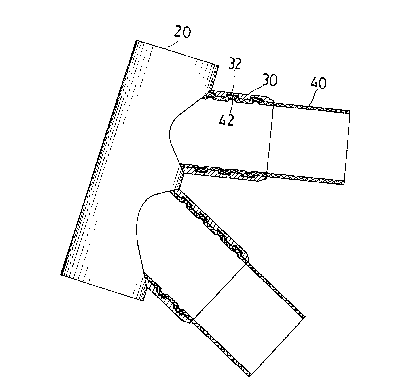
Fig. 4 is a sectional vie~ accordin~ to the
pressnt inventinn sbo~in~ that each fra~e tube has a
plurality of circular projections around the respective
outside surface respectively engaging the circular recesses
.. . .. . . .

~,~7~73
on the inside surface of a respective lug on a fra~e tube
cannectnr; and
Fi~. 5 illustrates an alternate for~ of the present
invention in ubich a reinforcin~ tube is inserted in each
frame tube to reinforce the connection.
DETAILED DESCRIPTION DF THE DRAWINGS
.
Referrin~ to Fig. 4, the present invention is
generally comprised of a fra~o tube connector 20 haYing at
least one lug 30. which receives a respective fra~e tubs 40.
Each lug 30 of the fra~e tube connector 20 has a plurality of
circular recesses 32 spaced fro~ one another around the
inside surface therenf. Each fra~e tube 40 is insartad in
the respective lug 30, and then treated through th~ process
Gf squeezing to for~ a plurality of spaced circular
projections 42 around the outside surface thereof
raspectively engaging the circular recesses 32 on tha
respectiv~s lug 30. Therefore~ each fra~e tuba 40 beco~as
tightly :retained in the respective lug 30 on the fra~e tuhe
connector 20.
Referring to Fig. 5~ a reinforcing tube 60 ~ay be

~0~73
inserted in each framQ tube 40 before the process of
squeezing. After the process of squee~ing, a plurality of
spaced circular projections 62 are for~ed around the outside
surface nf each reinforcing tube 60 and respsctively engagin~
the circular recesses Inot indicated) formed Dn the inside
surface of the circular projectiDns 42 of the respective
frane tube 40 to reinforce the connection. In practice,
the nu~ber of the circular recesses 32 on each lug 30 and the
nunber of the circular projections 42 or 62 on each fraae
tube 40 or reinforcing tube 60 may be changed accordin~ to
different requirements. The sbape of the cross section of
each circular recess 32 ~ay bE variously embodied.
~ .

Representative Drawing
A single figure which represents the drawing illustrating the invention.
Administrative Status

2024-08-01:As part of the Next Generation Patents (NGP) transition, the Canadian Patents Database (CPD) now contains a more detailed Event History, which replicates the Event Log of our new back-office solution.

Please note that "Inactive:" events refers to events no longer in use in our new back-office solution.

For a clearer understanding of the status of the application/patent presented on this page, the site Disclaimer , as well as the definitions for Patent , Event History , Maintenance Fee  and Payment History  should be consulted.

Event History

Description Date
Inactive: IPC from MCD 2006-03-11
Time Limit for Reversal Expired 1996-02-12
Application Not Reinstated by Deadline 1996-02-12
Inactive: Adhoc Request Documented 1995-08-14
Deemed Abandoned - Failure to Respond to Maintenance Fee Notice 1995-08-14
Application Published (Open to Public Inspection) 1994-02-13
All Requirements for Examination Determined Compliant 1992-08-12
Request for Examination Requirements Determined Compliant 1992-08-12

Abandonment History

Abandonment Date Reason Reinstatement Date
1995-08-14

Maintenance Fee

The last payment was received on 

Note : If the full payment has not been received on or before the date indicated, a further fee may be required which may be one of the following

  • the reinstatement fee;
  • the late payment fee; or
  • additional fee to reverse deemed expiry.

Please refer to the CIPO Patent Fees web page to see all current fee amounts.

Fee History

Fee Type Anniversary Year Due Date Paid Date
MF (application, 2nd anniv.) - small 02 1994-08-12
Owners on Record

Note: Records showing the ownership history in alphabetical order.

Current Owners on Record
YUNG-YUAN WU
YUNG-YUAN WU
Past Owners on Record
None
Past Owners that do not appear in the "Owners on Record" listing will appear in other documentation within the application.
Documents

To view selected files, please enter reCAPTCHA code :


To view images, click a link in the Document Description column. To download the documents, select one or more checkboxes in the first column and then click the "Download Selected in PDF format (Zip Archive)" or the "Download Selected as Single PDF" button.

List of published and non-published patent-specific documents on the CPD .

If you have any difficulty accessing content, you can call the Client Service Centre at 1-866-997-1936 or send them an e-mail at CIPO Client Service Centre.


Document
Description 
Date
(yyyy-mm-dd) 
Number of pages   Size of Image (KB) 
Drawings 1994-02-13 4 84
Claims 1994-02-13 1 25
Abstract 1994-02-13 1 20
Cover Page 1994-02-13 1 14
Descriptions 1994-02-13 6 147
Representative drawing 1998-08-20 1 11
Fees 1994-08-05 1 61
Courtesy - Office Letter 1995-10-17 1 18
Prosecution correspondence 1994-12-22 2 54
Courtesy - Office Letter 1993-01-18 1 30