Note: Descriptions are shown in the official language in which they were submitted.
WO 91/11133 PCI/Al)91/00016
2 ~ 3 2
TITLE
BATH SEAT ASSEMBLY
FIELD OF THE INVEN~IO~
This invention relates to a bath seat assembly for
assisting persons into and out of a bath tub.
BACRGROUND ART
Incapacitated or invalid persons, such as the aged,
infirm, paraplegics and others with physical disabilities,
often experience difficulties getting into and out of a bath
tub. For many such persons, the operation of bathing can be
quite dangerous and they are unable to enter and leave the
bath tub unassisted. Nurses in particular are frequently
required to lift patients, particularly elderly patients, into
and out of baths. Those confined to wheelchairs ~lso require
the assistance of others when bathing. Nurses and other
helpers often risk injury to themselves, eg. back sprain, when
lifting patients into and out of a bath.
Furthermore, the shape of the common bath tub, and
its slippery surface, make it notorious as a common cause or
site of many accidents in the home. Serious and sometimes
fatal accidents are known to have occurred when persons have
slipped and fallen when manoeuvring into or out of the bath
tub. Injuries such as broken arms, legs, hips or ribs
resulting from a fall can leave elderly or infirm persons
stranded in the bath. ;
Various devices have been proposed to assist persons
.to get into and out of the bath tub. Australian patent
application no. 23310/84 discloses a wall mounted elevatable
- - , . . .
: ~ - , , -, . - ................ - .: , ' , . -. : ''
- . , . ,. ~ .
' ~ ~ ! ' . , '
WO91/tll33 PCT/AU91/00016
q~ 2
bath seat whlch enables the seated bather to be gradually
lowered into the bath and raised therefrom. However, wall
mounted lifting devices are complex in construction and hence
expensive. Furthermore, the devices need to be installed by
professional trades persons and may not be suitable in all
bathrooms. The devices are permanent fixtures and, in the
event that they are removed, unsightly and unhygienic holes
will remain in the wall.
Australian patent application 83837/82 describes a
device for lifting invalids in bath tubs which uses
collapsible bellows to raise and lower a plate or stretcher on
which the bather rests. The collapsible bellows are inflated
by a household water supply such as taps. The disadvantage
with bellows is that while they provide vertical force for
lifting the bath stretcher, they tend to wobble and thus are
laterally unstable. For this reason, scissor linkages are
provided in and/or around the collapsible bellows to provide
the required support. As such linkages operate in soapy
water, the pivot joints are susceptible to corrosion and
clogging. Further, the whole apparatus is cumbersome and
heavy to use.
The applicants earlier patent application 18992/88
describes a self-supporting inflatable bath seat having an
inflatable bladder, and a seat portion on top of the
inflatable bladder, the bladder being characterised in that it
comprises a plurality of upright tubes spaced around its
~; circumference, the tubes being inflatable with air or water.
Th~ bladder is of a special design to allow it to be inflated
...... . . . - ~ - ~ , -
-', : : -
: .
, ~ .
WO91/11133 PCT/AU91/00016
3 2 ~ 3 ~
with the minimal amount of water or air. As the bladder must
be made specially for this application, it increases the
overall cost of the product.
DISC~OSURE OF THE INVENTION
It is an object of the present invention to provide
an apparatus for assisting a person into and from a bath which
may substantially overcome the disadvantages of the prior art.
In one form, the invention resides in an apparatus
for assisting a person into and from a bath, said apparatus
comprising
a frame assembly adapted to be positioned in a bath
and supported by a bottom wall of the bath, said frame
assembly including at least one guide member extending
upwardly in use,
a bath seat slidably connected to the at least one
guide me~ber for movement between a raised position adjacent -
an upper portion of the bath and a lowered position adjacent a
lower portion of the bath, and
an inflatable bladder operatively associated with
the bath seat to move the bath seat between the raised and
lowered positions upon inflation or deflation of the bladder.
The frame assembly suitably includes a plurality of
leg members to facilitate the apparatus to be free standing.
The plurality of leg members may include front leg members and
rear. leg members. Suitably, a pair of spaced front leg
members and a pair of spaced rear leg members are provided.
The front leg members are sui~ably interconnected by
one or more interconnecting member~. Suitably, an
~ ., ' '. , ''
....
WO91~11133 ~ ' PCT/AU91/00016
interconnecting member extends between lower ends of
respective front leg members and the interconnecting member
may also be engagable with a support surface such as a bath
floor.
Similarly, the rear leg members may be
interconnected by one or more interconnecting members.
Suitably, a lower interconnecting member extends between lower
ends of the rear leg members and may be engagable with a
support surface. Upper ends of the rear leg me~bers may also
be interconnected by an upper interconnecting member.
Suitably, the, front leg members and rear leg members
are interconnected by side interconnecting members. The side
interconnecting members may extend from adjacent upper
portions of the front leg members to an intermediate- portion
of the rear leg m,embers. The side lnterconnecting members can
assist in providing a rigidity to the frame assembly and may
also function as arm rests when the bath seat is in the
lowered position.
The frame assembly may be stabilised against
,20 movement along the bath by one or more movement inhibiting
members. The movement inhibiting members may comprise suction
pads which can secure the frame assembly to a bottom wall of
the bath. Alternatively, the movement inhibiting member may ,
include an anti-slip pad formed from suitable material such as
rubb,e,r. In a further alternative, a non-slip mat may be
placed between the apparatus and a bottom wall of the bath
onto which the apparatus is positioned.
A support means may he proviaed to support the
: ~ .
~ ~ .
WO91/11133 PCT/AU91/00016
5 2~7;~32
inflatable bladder and especially a lower portion thereof.
~he support means may be supported by the frame assembly. The
support means suitably comprises a support platform to support
a bottom wall of the inflatable bladder. The support means
may extend between the front and rear leg members adjacent
lower portions thereof and is suitably supported by the leg
members or respective interconnecting members.
The at least guide member is suitably located
adjacent the reàr leg members. Suitably, a plurality and
preferably two such guide members are provided. The or each
guide member suitably extends between the lower
interconnecting member and upper interconnecting member
interconnecting the rear leg members. It is preferred that
the or each guide member is secured to the rear leg members
and/or respective interconnecting members. The or each guide
member may be inclined.
Preferably, the or each guide member has a
substantially cylindrical outer configuration. It is further
preferred that the parts of the frame asse~bly such as the leg
members and interconnecting members are formed from
interconnecting tubes.
The bath seat suitably includes one or more
connecting portions which can be slidably connected to the at
least one guide member thereby slidingly connecting the bath
seat thereto. The connecting portions preferably comprise
collars extending at least partially about a respective guide
member. It is preferred that a number of collars are coupled
to each respective guide member.
: . ,
''
: .. .. .
WO91/11133 PCT/AU91/00016
~ ~ ` 6
The connecting portions are suitably coupled to a
back support portion of the bath seat.
- Various invalid retaining accessories such as
security belts may be associated with the bath seat or the
apparatus. The bath seat may be formed from moulded plastics
material to resist corrosion or degradation upon repeated
immersions into the bath water. The bath seat may include
drainage apertures or ridges to allow water to drain from the
seat with a person seated thereon.
In the manner described above, the bath seat can
slide up and down relative ~o the guide member while still
being coupled thereto. It should be appreciated however that
other types of connections between the bath seat and the frame
assembly can be made.
The bath seat may be pivotally connected to the at
least one guide member to enable it to be swung to one side of
the bath so that a person can be seated thereon and then
subsequently swung back into the bath. Alternatively, the
bath seat may include a pivoting portion to allow a person to
pivot to the side of the bath to facllitate exit from the bath
seat when the bath seat is in the raised position.
The inflatable bladder is preferably located below
the bath seat and preferably between the bath seat and the
support means. ~he inflatable bladàer is typically formed of
a fl.exible fluid impervious material and preferably is
substantially inextensible. The 1nflatable bladder may
comprise plastics, rubber, metallic foil or combinations
thereof. The bladder may encapsulated in a flexible
' ~ :
.
- .
,~: ; , ~ . :.
WO91/11133 PC~/AU91/00016
2 ~ 3 ~
inextensible surround of fabric or mesh material to inhibit
over inflation.
Preferably, a pressure relief valve is associated
with the inflatable bladder to prevent overinflation of the
bladder. The pressure release valve may be in the form of a
constricted opening in the bladder.
The bladder ~ay comprise a single inflatable body or
a plurality of separate inflatable bodies which may be
interconnècted. The bladder may comprise a bellows-type
configuration. The bladder may be inflated by any suitable
source of pressurized fluid, suitable fluid including
compressed air or more preferably pressurized water.
Preferably, the bladder is filled by a source of pressurized
water which suitably comprises tap water. The bladder may ~e
fixed to the frame assembly and/or bath seat or may be formed
separately therefrom. Preferably, the bladder comprises a
cylindrical inflatable body which may be tapered such that
upon deflation the bladder collapses onto itself.
The bladder may be inflated or filled through an
inlet coupled to a source of pressurized fluid through a
suitable supply conduit. The supply conduit may extend
partially through a portion of the frame assembly.
Preferably, a valve is associated with the conduit to regulate
fluid entry into the inflatable bladder.
BRIEF DESCRIPTION OF THE FIGURES
In order that the invention may be more fully
understood a preferred embodiment will now be described with
reference to the accompanying drawings in which
WO91/11133 ~q~ PCT/AU91/00016
8 -
Figure 1 is a perspective view of the apparatus
according to a preferred embodiment of the invention.
Figure 2a is a side section elevation view of the
apparatus of Figure 1 in a lowered position .
S Figure 2b is a side section elevation view of the
ap~aratus of Figure 2a in a raised position.
BEST MODE OF CARRYING OUT THE INVENTION
-
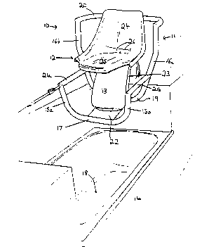
Referring to Figure 1 there is disclosed an
apparat~-s for assistin~ a person into and from a bath. The
apparatus 10 comprises a frame assembly 11, a bath seat 12 and
an inflatable bladder 13.
The apparatus is dimensioned to allow it to be
positioned into a bath tub shown generally as 14.
~rame assembly 11 is formed from a number of
interconnecting tubes and includes a pair or spaced front leg
members 15a, 15b and a pair of spaced rear leg members 16a,
16b.
Lower portions of front leg members 15a, 15b are
interconnected by a transverse interconnecting member 17. In
the embodiment, front leg members 1Sa, 15b and
interconnecting member 17 are formed form a unitary tubular
~member. Interconnecting member 17 engages with a bottom wall
18 of bath tub 14 in use.
Lower portions of rear leg members 16a, 16b are
~ inte~connected by a lower transverse interconnecting member 19
; and upper parts of rear leg members 16a, 16b are
interconnected by an upper transverse interconnecting member
20.
::
~:
. . - .: - . ,
WO91/11133 PCT/AU91/00016
- ~ - 2 ~ 7 .~ 9-3 ;~ - - - -
- -
Upper portions of front leg members 15a, lSb are
connected to intermediate portions of rear leg mem~ers 16a,
16b by side interconnecting members 2la, 2lb. The side
interconnecting members 21a, 21b function as arm rests for a
person when bath seat 12 is in the lowered position, and
provides rigidity to the frame assembly.
A support means in the form of a platform 22 extends
between interconnecting members 17 and 19 and is secured
thereto. Platform 22 provides support for the bottom wall of
infl-atable bladder 13.
A pair of spaced guide members 23 (only one shown in
the Figures) is located between lower interconnecting member
19 and upper interconnecting member 20 and comprises a
generally cylindrical tubular body. Upper and lower ends of
guide members 23 are secured to interconnecting members 19 and
20 respectively.
Bath seat 12 in the embodiment comprises a seating
po~tion 25 and a back support portion 24. The seat is
typically moulded from plastics material and can include
drainage apertures 26 to drain any fluid from the seat portion
25.
As more clearly illustrated in Figures 2a and 2b,
the ~ear of back support portion 24 includes a pair of spaced
: connecting portions in the form of collars 27 which are in
linear alignment and uhich extend about a respective guide
member 23. Although not illustrated in the drawings, a second
pair of collars extend about the second guide member.
Inflatable bladder 13 comprises a generally
-
~ ~ .
~: ~: ~ ' " ' ' '
. . . . . . .
W091/11133 PCT/AU91iO0016-
cylindrical hollow body which in the embodiment is formed from
vinyl plastic.
sottom wall 28 of bladder 13 is supported by
platform 22 while top wall 29 of bladder 13 abuts under seat
portion 25 and can be connected thereto.
Bladder 13 includes a fluid inlet 30 connected to a
supply conduit 31 which extends through side interconnecting
member 21a and to a soùrce of pressurized fluid such as a
water tap 32. A valve 33 is conveniently located adjacent the
end of interconnecting member 21a to allow it to be easily
manipulated by a person seated on the bath seat.
To prevent over inflation of bladder 13, a pressure
release valve 34 is provided adjacent an upper portion of the
bladder to which is connected a ~hort length of conduit 35.
~alve 34 is permanently open but has a constricted diameter
thereby allowing .inflatable bladder 13 to be inflated but not
overinflated.
In use, the apparatus can be placed inside bath with
interconnecting members 17 and l9 supporting the apparatus
from the floor of the bath. The .inflatable bladder is
connected to a bath tap via supply conduit 31. As the bladder
is filled with wa~er, the bath seat rises from the position
shown in Figure 2a to the position shown in Figure 2b. The
bladder is dimensioned such that when it is inflated, the bath
seat... is approximately the same level as the rim of the bath
tub. A person can sit on the bath seat and switch off valve
33 whereby the weight of the person results in water flowing
through pressure release valve 34 thereby deflating the
': .- ', ,: ~
. .: .,: .. . . .
WO91/11133 PCT/AU91/00016
3 ~
bladder to move the ~ath seat from the position shown in
Figure 2b to the position shown in Figure 2a. It should be
appreciated however that instead of pressure release valve 34,
a further outlet valve may be used (not shown) to empty
bladder 13. When the person has finished bathing, valve 33 is
opened to allow water to flow into the inflatable ~ladder
thereby moving bath seat 12 back to its position shown in
Figure 2b at which time the person may alight from the bath.
The apparatus according to the invention has several
advantages. Firstly, the apparatus is portable and is not
bolted or otherwise fixed in a non-removable fashion to the
bath or a bath surround portion. The apparatus is lightweight
and can be easily placed into a bath. The apparatus is
freestanding and does not require additional braces or stru.s
to position it in a bath tub. The apparatus is formed from
relatively few simple parts and is therefore inexpensive to
manufacture and less susceptible to breakdown.
~he apparatus although particularly suitable for a
bath tub can also be used for spa tubs, therapeutic baths and
other bathing devices which are difficult to enter into or
exit from by frail or elderly people.
It should be appreciated that various other changes
or modifications may be made to the embodiment described
without departing from the spirit and scope of the invention
as d~fined in the appended claims.
. , , .:, . : . ~ . .-. , . . - -