Note: Descriptions are shown in the official language in which they were submitted.
~7r)9~1
WO91/12169 PCT/NO91/00022
~''~: .
Equipment for recovery of liquid tank cargo from a vessel.
The present inventlon relates to equipment for recovery of
llquid tank cargo from a vessel at sea, such as a tanker having
an oil cargo, in the case of a leakage, for instance by running
aground.
It has shown to be nearly impossible to prevent a disaster when
oil leaks from a tanker, when the leakage itself cannot be
stopped. Recovery of the oil that has leaked out has shown to
be little efficient.
.
The present invention relates to equipment being defined in the
succeeding claims.
The background of the invention is the little efflcient
recovery of the leaked oil which has been attempted and the
appreciation that the problem can be attacked in a
substantially different manner, by limiting the leakage itself
substantially.
This is achieved with the equipment according to the invention,
which constitutes stand-by equipment to be used as immediately '
as possible after a leakage from a tanker has been discovered,
in order to limit as far as possible the ~uantity of leaking
oil.
: ' '
Oil is usually transported in tankers in such a manner that the
oil level in the tanks of the vessel is higher than the water -
level outside the vessel. Moreover, an excess pressure is
usually established by means of an inert gas above the oil, in
order to prevent evaporation of oil. Thus, if the formation of
a hole occurs in the bottom of the vessel, oil will be forced
out because of the excess static pressure of the oil relatively
to the static pressure of the water surrounding the vessel, and
the excess pressure of the gas above the oil will contribute to
increase the leakage of oil. If nothing is done to prevent the
leakage, except that the excess pressure may come to an end
:, , . ~ . : : .
~ ; ,, i . :
W ~ 1
WO91/12169 PCT/N091/000~
wh~n the volume of the free space above the oil increases due
to the leakage, the leakage may continue untll a static
equilibrium between the remaining oil in the vessel and the
surrounding sea water has been established. When such an
equilibrium occurs very large quantitles of oil may have leaked
out, and a disaster will usually be a fact, even if attempts of
recovering the oil from the sea are made.
The primary purpose of the equipment according to the present
invention is to stop the leakage itself, by as quickly as
possible to pump oil out of the vessel or from the tank or
tanks of the vessel from which leakage occurs, whereby the oil
is collected in a container which is carried along or stored
in a collapsed state and which in a case of leakage is placed
in the sea, whereupon oil is pumped from the vessel and into
the container.
:'~
Preferably a low pressure is established in the free space of
the vessel above the leaking oil, in order to limit the outflow
of oil. The pumping of oil to the container floating in the sea
is, however, the most important, in order to reduce the oil
level inside the vessel so that the static excess pressure of
the oil relatively to the static pressure of the sea water in
the leakage area diminishes and preferably is eliminated or
becomes so small that continued leakage can be prevented by the
low pressure.
The collapsed container, which may for instance lie on the deck
of the vessel, can be permanently coupled to a hose connected
to a pump in the vessel. The hose can be wound on a drum, and
the collapsed container, which can be made of a fabric, may for
instance be stored on some kind of a catapult device, in order . --
to be hurled onto the sea.
~ -
A pump for establishing low pressure above the leaking oil may
also be permanently connected and ready for use.
The equipment according to the present invention can also
- - , . :-. : - . ,- , . . .: . . .
. . . , . : : .
,~
:: . ~ . .: . ~, : .
~-, ,, ~ , : , : :
:, . ~ ; .:: : ,, . . :: .: ,. . . ,~:, :-:. . .
: . . - :. .. .. .. ... .
2 ~ 7 ~
W~91/12169 PCT/NO91/0002
constitute a mobile unlt whlch comprises a collapsible fabric
container and a hose being wound on a drum and coupled to the
container, whereby the container in collapsed condition is
releasably fastened to a stand in wh}ch the drum is journalled.
Moreover, the unit may comprise another drum with a hose
adapted to be introduced in a leaking tank in a vessel, and the
two hoses may be coupled together. A pump may be interposed
between the two hoses.
Such a mobile unit ~or several) according to the invention can
be permanently situated aboard a vessel, but the most important
use is assumed to be that several units are placed on land,
preferably in coastal areas, in order that they may be carried
by helicopters or seagoing vessels to a leaking vessel. After
having been brought to the vessel the unit is made ready for
use, in that the fabric container is hurled onto the sea, the
stand is placed on a deck on the vessel and the hose being
coupled to the container is brought in communication with the
leaking tank in order to pump oil into the fabric container.
: : ,
In order to be efficient the fabrïc container must have a large
volumetric capacity, but the capacity will in practice be
limited by the total weight of the unit in its stand-by
condition, depending on how the unit is to be transported, when
it is assumed that it is situated on land. For transportation
by helicopter the weight should presumably be limited to about
3 tons, and this is supposed to permit a volumetrlc capacity of
the fabric container of up to about lO.000 m~. For transpor-
tation by seagoing vessels the limit is of course substantially
higher.
~n order to prevent that the container, when lying in the sea
and receiving oil from a leaking vessel, drifts away so that -
the hose for transfer of oil is torn apart, it may be necessary
to moor the container to the vessel. The unit may for this
purpose also conveniently comprise a third drum carrying a
mooring line.
.: . : . ........................ : - . , . . :
., . ~ ~ - , . : .-. .
.:
.
2 ~ o l
WO91/12169 PCT/NO91/0002~
In the stand-by condition the container in a collapsed state
may slmply be fastened to the stand by suitable means, but
preferably in such a manner that the container ca~ be released
from the stand whlle the stand is hanging below a helicopter.
It may for instance be used strap fasteners which can be
released from the helicopter. The container may, however, be
situated in some kind of a cover, for instance a bag or a box.
The bag may for instance have an opening in the bottom which is
closed during storage and transportation and which can be
opened from the helicopter in order to be dropped onto the sea,
for instance by cord release. Correspondingly the box may have
a lid which can be opened from the helicopter, or the box may
be open along one side or end, for pulling out the container. :
The invention will be explained more detailed in the following,
by means of dlagrammatlcally shown examples, with reference to
the accompanying drawings.
Fig. l shows equipment which can be in a permanent stand-by
condition aboard a vessel, in order to be taken into use
immediately when a leakage occurs.
Figs. 2 and 3 show equipment in the form of a mobile unit.
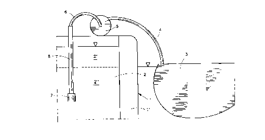
Fig. l shows a vertical section through a portion of a tanker
l, which is presupposed to have a leakage in the bottom
portion, so that oil in a tank 2 flows out into the sea. The ~ ;
Fig. shows a ballast room l' at the outer side of the tank 2.
The Fig. illustrates the use of the equipment according to the
invention, which comprises a flexible container 3 of fabric,
situated in the sea near the vessel l and connected to the
vessel through a hose 4, through which is pumped oil from the
tank 2 to the container 3. The vessel is equipped with a pump 7
for the pumping and a vertical tube 8 in the tank 2, and
another hose 6 connects the tube 8 to a drum 5, on which the
hose 4 has been wound before use.
Prior to being used the container 3 has been stored aboard the
vessel, for instance on deck, in a collapsed condition. The
.. . :, . . . . . .................................. .
: . ; ~ .
~- - - , : ,
2~75r~
WO91/12169 PCT/NV91/00022
container 3 may conveniently be stored on a catapult device, in
order to be hurled onto the sea for being used.
In the situation shown the tank 2 contains a quantity of oil 2
situated below the sea water level outslde the vessel l, and a
quantity of oil 2~ is situated above the sea water level. '
Despite the lower density of the oil relatively to the sea
water the difference between the levels (before any substantial
quantity of oil has leaked out) is usually so large that the
static oil pressure at the bottom of the tank 2 is higher than -
the statlc sea water pressure at the same level on the
outside. The mentioned excess pressure caused by gas above the
oil acts in addition to this. In a case of leakage this excess
pressure can simply be interrupted, and the equipment according
to the invention may comprise (not shown) means for estab~
lishing a low pressure above the oil. This implies that it is
not necessary to lower the oil level in the tank 2 down to the
sea water level outside the vessel in order that the outflow of
oil into the sea shall stop. The outflow will stop at a higher
oil level than the sea water level. This level difference is
determined by the difference of density between the oil and the
sea water and by the degree of low pressure. By as rapidly as
possible establishing a low pressure and pumping oil o~t and
into the container 3 until the level difference has been
achieved a further outflow of oil into the sea can be
prevented. It is, consequently, only necessary to pump out a
fraction of the oil contents in the tank 2 in order to stop the
outflow of oil through a hole in the bottom of the vessel.
For a large tanker a container adapted to contaln 30.000 m' of
oil will be sufficient. Such a container, made of fabric, may
have a weight of approximately lO tons, and the necessary
auxiliary equipment, for instance a catapult, a drum with hoses
and tubes and possibly a suction device for establishing low
pressure may have a weight of approximately 5 tons.
The esta~lishing of low pressure above the oil in the tank 2 is
of great importance with respect to stopping the outflow or oil
. , - ,, :
~: . . ~ '' ' : :
::;: , .
.
,,
WO9l/12169 ~ ( 3"l~ ~ PCT/NO9l/V002~
rapidly. A partlal vacuum of 0,5 atm. (50 kPa) corresponds to a
water column of 5 m and a somewhat higher oil column.
A contalner 3 made of a suitable fabric and havlng an oll
capaclty of about 30.000 m' lS able to be packed together to a
package of about 6 ml for being stored aboard a vessel. In
stead of stor1ng the container on a catapult it may of course
be stored to be hoisted overboard. The container may be
permanently coupled to the hose 4 which is wound on the drum 5,
and also the hose 6, the tube 8 and the pump 7 may be
permanently lnstalled and ready for use.
The container 3 may also be suspended in davits, like a life
boat, in order to be lowered to the sea.
Figs. 2 and 3 show equlpment according to the invention, in the
form of a mobile unit, and show the unit seen from the side and
from one end, respectively.
The shown unit comprises a collapsed fabric container 3~, which
in the example is situated inside a box 12. The box 12 is
fastened below a stand 14, in which are journalled three drums
15, 16, 17. Each drum has two end discs 18 and a hub, which
together define the space where a hose or a line is wound. The
hoses and the line are not shown. The shown stand 14 is
constituted by rods 19, 20, 13. The lower rods 19 constitute a
bottom frame, and the rods 20 are inclined upwardly from the
rods 19 and are fastened to an upper, horisontal top rod 13.
Between the rods 20 at each end of the unit is fastened a slab
11 providing support for a shaft 21 which carries the drums 15,
16, 17. At the top of the top rod 13 are fastened loops 10
which can be used for attachment of hoisting means.
A hose, which preferably is permanently coupled to the
container 3~, is wound on the drum 15. Another hose, adapted to
be put into communication with a leaking tank in a vessel, is
wound on the drum 16. A mooring line for the fabric container
3' is wound on the drum 17.
,, .
.. .. . . ..................... .
~. . ~ , .
2~7~
WO9ltl2169 PCT/NO91/0~022
In the case that the unit comprises two hoses, each of which
being wound on its own drum, the hoses may be permanently
coupled together. This may for instance be achieved in that the
inner ends of each hose are equlpped with a pipe bend in
communication with the inside of the shaft 21, which is in the
form of a tube . This tube is of course closed, so that oll can
only flow from the drum 16 to the drum 15, i.e. without flowing
axially out from the tube. A simple solution consists in that
the drums 15 and 16 are fastened to the tube 21, so that the
drums have to rotate simultaneously and uniformly. To the
contrary , in order to achieve that the drums can rotate
independently of each other, a two- part tube 21 can be used,
having a swivel coupling between the two parts. This is per se
known technique, and will not be described any further. ;~
The two hoses do not necessarily have to be in mutual communi-
cation while they are wound on the drums. It is possible to
interconnect the inner ends of the hoses after they have been
unwound. A separate hose can be used for the interconnection,
and a pump can be coupled therein, possibly combined with a
motor. The separate hose and the pump can be mounted on the
unit. The motor can be an electric motor, a pneumatic motor, a
hydraulic motor or an internal combustion engine.
The stand structure shown in the drawing is purely diagrammatic.
The shown rods 19,20,13 can have any kind of cross sectional
shape and be made of any kind of suitable materials. Taking
into account a favourable relationship between strength and
weight an aluminium aLloy may be well suited. The stand needs,
moreover, not consist of rods or solely of rods. A structure
consisting entirely or partially of plates may also be used.
What in the principle is necessary is a stand wnich constitutes
a support for one or more drums.
The hoses being used, as well in the permanent as in the mobile
equipment, can be of any kind of suitable type, and this also
applies to the fabric container. The latter can be made of a
laminate which comprises a thin cloth of high tensile strength
: i. . . .
' , , .' ' ', '- '' ' ' '' '; : ~' .' '
", . ~ . .
.
2 ~)3v'3'~
WO91/1Z169 PCT/NO91/0002
and a layer on the inside which seals against llquid
penetration. Of course, a layer may also be situated on the
outside. In order to prevent that the fabric container ruptures
as a result of rubbing against a side of a vessel it may
entirely or partly consist of a double cloth ar-d a suitab-
le filler material between the cloth layers. For lnstance
expanded polystyrene can be used as filler material. The fabric
container can, however, be given such a shape that it takes a
well defined floating position in the sea, and in such a case
filler material may be used only in the outermost side
portions, in order to limit the volume of the container in its
collapsed state.
;
The equipment according to the invention can of course be used
by leakage of any kind of liquid which the container can
withstand to contain, and the container can be made of
materials which withstand all liquids in question.
It is to be noted that the volumetric capacity oE the container
does not need to correspond to the total amount of liquid in a
leaking tank. It is sufficient t~ pump out as much liquid from
the tank that the static liquid pressure at the leaking spot '
becomes lower than the static sea water pressure outside. A
unit according to the invention, therefore, can be used to stop
a leakage from a tank containing a liquid volume which is
several times as large as the liquid volume with which the
container can be filled.
,
- , . . .
.:
. : . : .,.,.. ,, , : :
... . ' , ~ , . : ' " ,: ~ :