Note: Descriptions are shown in the official language in which they were submitted.
CA 02076115 2004-02-17
LIQUID RE.'~iOVAL APPARATUS AND METEOD
FOR WOOD PULP
10
Background of t~:e Invention
a.~ Field of the Invent' on
The present invention relates to an apparatus and
method for liquid removal for wood pulp, and more
particularly to such an apparatus and method which is
particularly adapted for dewatering and/or washing
material such as wood pulp or the like, and in a
preferred form, both dewatering and washing.
b. Background ~?rt
In the pulp and paper industry, there are in
general three ccmmon :rethods of accomplishing a
dewatering and/or washing operation. One method is to
employ a rotating drum which has a perforate cylindrical
sidewalk where the cylindrical sidewall on one side
travels downwardly into a bath of a pulp slurry and then
travels upwarciy to a location above the pulp slurry
bath. A suction is applied within the drum, so that a
portion of the pulp slurry adheres to the surface of the
drum. As the layer of wood pulp on the drum is carried
upwardly above the pulp slurry bath, in a-first path of
_ 2~'~fill
travel a dewatering operation is accomplished where the
water from the pulp slurry is drawn into the interior of
the drum. Then in a second part of the travel of the
pulp on the drum, a wash water is deposited on the pulg
mat that has been dewatered to cause displacement washing
to be accomplished. Before the layer of pulp material
that has been dewatered and washed travels back into the
pulp bath, this layer is removed from the drum by a
doctor blade or the like. The drum is sometimes enclosed
in a pressure chamber. and for practical reasons, the
pressure differential used in the drum-type
dewatering/washing operation is in the range of about
four to ten pounds per square inch.
A second method is to use a continuously moving
foraminous conveyor belt onto which a wood pulp slurry is
deposited. The conveyor belt carries the wood pulp
slurry sequentially over a series of suction boxes which
create a lower than atmospheric pressure below the belt
to apply a differential pressure across the moving
conveying belt to pezform first a dewatering operation,
and then a washing operation where wash water is
deposited on the layer of wood pulp. In this type of
operation, the pressure differential that can be applied
across the pulp layer is limited because of the
frictional force created between the moving belt and its
underlying support structure, and the pressure
differential limitations in such devices are generally in
the range of about two to three pounds per square inch.
A third type of dewatering/washing operation is
to move the pulp between upper and lower foraminous belts
which are pushed toward one another to squeeze the water
3 - 2~'~~1~~3
from the pulp. Then the pulp is mixed with a cleaning
liquid, and the liquid removal operation is again
repeated by again squeezing the pulp. This series of
steps is continued until the desired dewatering and
washing is accomplished.
To the best knowledge of the applicant, all of
the dewatering/washing systems that have actually been
used commercially operate with pressure differentials in
the range of two to ten pounds per square inch. but no
higher. As will be discussed later herein, the pressure
differentials in the present invention are substantially
higher, even up to three hundred PSI or higher.
2~~ 6~.~.J
Summary of the Tnvention
The present invention comprises an apparatus to
accomplish liquid removal from a pulp slurry where a
slurry is moved into an above atmospheric pressure
chamber and deposited as a layer over a processing area.
A pressure differential is imposed at said layer while
said layer is stationary at said processing area to
remove liquid therefrom. Then the pressure differential
is reduced ipreferably to zero) and the layer is removed
from the processing area. The apparatus comprises a
pressure vessel defining the pressure chamber. There is
means to pressurize the pressure chamber to an above
atmospheric pressure level. Input means are provided to
supply pressurized pulp slurry into the pressure chamber
and deposit the pulp slurry as said layer at the
processing area.
There is a table assembly which has a perforate
support surface means for receiving the pulp slurry
thereon, and which is arranged to contain the pulp slurry
in the processing area that is located over the support
surf ace. The support surface means is arranged to be
exposed to pressure in said pressure chamber.
There is infeed means to direct a portion of the
pulp slurry under pressure into the chamber and onto the
surface as a layer, with the containment means containing
the layer in the processing area at a stationary location
relative to the support surface. The table assembly
defines a pressure differential table below the support
surface.
There is pressure differential means to
selectively create a pressure differential between the
~0'~~~.~ 5
- 5 -
pressure differential chamber and the pressure chamber
defined by the vessel, while maintaining the pressure in
the vessel. This is done with the pulp slurry on the
surface means to cause liquid to flow from the pulp
slurry to the pressure differential chamber. The
pressure differential means is also adapted to
selectively reduce the pressure differential.
Removal means are provided to remove the pulp
slurry after liquid removal therefrom, and after the
pressure differential is reduced, while continuing to
maintain the pressure in the pressure chamber.
Desirably, the pressure chamber extends both
above and below said table assembly, and more desirably,
the entire table assembly is positioned within said
gressure chamber. Also, the table assembly has
containment means around the processing area.
In the preferred form, the table assembly
comprises a table unit having upper and lower plate means
defining the pressure differential chamber. Further, the
table assembly comprises compression load means
positioned between the upper and lower~plate means to
resist compression loads from pressure in the pressure
chamber. The compression load means in the preferred
form subdivides the differential pressure chamber into
subchambers.
More specifically, the containment means
comprises a frame means extending around the processing
area to contain the pulp slurry in the processing area.
Further. in the preferred form at least a portion of the
frame enclosure means is moveable between a first
position adjacent to the perforate support surface means
2i~7~~.1
so as to contain the layer, and a second position where
at least a portion of the frame enclosure means is spaced
away from the support surface means. The assembly
further comprises a frame actuating means to move the
frame enclosure means between said first and second
positions.
Further, in the preferred form, the support
surf ace means and the removal means comprises a
foraminous conveying belt assembly which comprises a
conveying belt means and power means to move the belt
relative to the processing area.
Another feature of the present invention is that
there is in the pressure chamber a contact plate means
which is moveable from an upper position above the
processing area downwardly to a contact position where
the contact plate means presses against the pulp slurry
to enhance liquid removal. Further, the contact plate
means has opening means therein leading from above the
contact plate to said processing area. The apparatus
further comprises washing liquid input means to direct a
washing liquid into the pressure chamber and onto the
contac= plate means where the washing liquid passes
through the contact plate opening means to pass into said
layer.
Preferably, the contact plate means comprises a
plurality of contact plate through openings spaced over
the contact plate means. The contact plate means has a
lower contact surface formed with a plurality of recesses
defined by slanted recess walls that slope downwardly and
divergently from the contact plate openings.
_.
One form of the contact plate recesses comprises
grooves extending along a plurality of contact plate
openings.
Another feature of the present invention is that
the pressure differential means further comprises tube
means connecting to the pressure differential chamber.
Also, there is equalizing valve means arranged to
selectively interconnect the pressure differential
chamber with the pressure chamber. There is pressure
reduction valve means which connects the tube means to a
lower pressure area to create the lower pressure level in
the pressure differential chamber.
In a preferred form, the tube means comprises a
plurality of tubes, each of which has a pressure
reduction valve means. Thus. liquid removed from the
pulp layer can be selectively directed through one or
more of said tubes.
To provide recirculation of the washed liquid, at
least one of the tubes is directed to a liquid collecting
location, and there is a recirculating line transmitting
liquid as recirculated liquid from the liquid collecting
location back to the pressure vessel. This recirculated
liquid can then be used as wash liquid for said layer.
There is a fresh water liquid inlet to introduce
fresh liquid into the pressure vessel to be used as wash
liquid. and a discharge lia_uid outlet to dispose of at
least a portion of the liquid removed from said layer.
Also, in the preferred form there is a plurality of tubes
which direct liquid from said layer to respective
collecting areas. and a plurality of recycling lines to
_ g _
direct the collected liquid back to the pressure vessel
for use as Wash liquid in successive wash cycles.
A further feature of the present invention is a
layer discharge means to remove the layer from the
pressure chamber. This comprises a passageway having an
inlet to receive the pulp mat from the conveying belt
means. The discharge passageway is sized and configured
to receive the pulp mat in substantial sealing
relationship to the passageway. The passageway leads to
a lower pressure location outside of said pressure
chamber. The discharge means further comprises control
outlet discharge valve means through which the mat is
discharged from the lower pressure location.
The discharge means further comprises pressure
discharge valve means to direct a pressurized fluid
medium to act against material of said layer being
discharged from the discharge passageway to move the
material through the outlet discharge valve means. In a
preferred form, the pressurized fluid medium is directed
from the pressure chaaber through the pressure discharge
valve means to act against the material from the mat.
The present invention desirably creates a
pressure differential at least greater than 10 FSI, more
desirably 20 PSI and yet more desirably at 50 to 100 PSI.
In some instances, there may be advantages to go to yet
higher pressures, such as 300 PSI or 500 PSI. This could
be particularly advantageous, for example, where the pulp
material to be processed in the present invention is
being previously processed at a higher level, such at 300
PSI or 500 PSI. Also, desirably the liquid removal is
accomplished at a higher temperature which is related to
~~~~1~
the temperature to which the liquid (usually water) can
be raised at the operating pressure.
In the method of the present invention, the pulp
slurry is directed into a pressure chamber and deposited
as a layer over a processing area. While the pulp layer
is stationary at the processing arear a pressure
differential is applied across the pulp slurry to effect
a liquid removal operation. Then the pressure
differential is reduced (desirably to zero) after which
the material is removed.
Other features of the present invention will be
apparent from the following detailed description.
la _
Br ief Descr iution of the Drawings
Figure 1 is a side elevational view, partially in
section, showing a first embodiment of the apparatus of
the present invention;
Figure 2 is transverse sectional view taken along
line 2-2 of Figure 1 at the dewatering area of the
apparatus of the first embodiment;
Figure 3 is a transverse sectional view taken at
line 3-3 of Figure 1 at the washing area of the
apparatus;
Figures 4 and 5 are two side elevational views.
similar to Figure 1, but showing two main portions of the
apparatus of the present invention separated from one
another in position to be assembled;
Figure 6 is an isometr is view showing a portion
of the conveying and pressure differential table unit of
the presen t invention;
Figure 7 is a view similar to Figure 1, but
showing a second embodiment of the present invention:
Figure 8 is a view similar to Figure 3 showing a
third embodiment of the present invention;
Figure 9 shows a modified form of the conveying
belt of the present invention.
Figure 10 is a side elevational view. taken
partly in section, showing a fourth embodiment of the
present invention;
Figure 11 is a sectional view taken along line
11-11 of Figure 10;
' . .. . ..,;,::z~. '.'. w
- 11 -
Figure 12 is a top elevational view of only .the
pressure vessel of the fourth embodiment of Figure 10,
showing various locations of the openings therein;
Figure 13 is a side elevational view of the
pressure vessel of Figure 12, showing in addition certain
fittings;
Figure 14 is a side elevational view showing only
the headbox and manif old assembly which provides the pulp
for processing in this fourth embodiment;
Figure 15 is front elevational view of the
headbox and manifold assembly of Figure 14;
Figure 16 is a top elevational view thereof;
Figure 17 is a transverse sectional view showing
a portion of the table unit and a top portion of one of
the conduits to which it is attached;
Figure 18 is a top plan view showing only the
recirculating tubes used in the fourth embodiment;
Figure 19 is an end view of the tubes of Figure
18, taken at line 19-19 of Figure 18;
Figure 20 is a side elevational view of the tubes
of Figure 18, taken at the location of line 20-20;
Figure 21 is a perspective view of a portion of
the contact plate of the fourth embodiment;
Figure 22 is a somewhat schematic view of the
liquid recirculating system of this fourth embodiment:
Figure 23 is a schematic drawing, shown partially
in the form of a graph. showing the manner in which the
liquid recirculation takes place in the fourth
embodiment;
Figure 24 is a side elevational view of the pulp
discharge assembly of the fourth embodiment;
- 12 -
Figure 25 is a top elevational view of the
discharge assembly of Figure 27;
Figure 26 is an isometric view of the discharge
assembly as shown in Figures 24 through 25;
Figure 27 is an isometric view of the conveying
belt of the fourth embodi:rent, and showing also the
rollers associated therewith; and
Figure 28 is a transverse cross-sectional view of
the contact plate.
to
.. . . ._..,:::~~:~., :. ..
- 13 -
~~'~b~.~~
Description of the First Embodiment
It is believed that a clearer understanding of
the present invention will be obtained by first
describing somewhat briefly the main components of the
apparatus of the first embodiment of the present
invention, followed by a general description of its
operation. After this, there will be a more detailed
descr iption of the first embodiment and also more
specifics of its operation. Then there will be
descriptions of further embodiments.
(a) General Description of the Apparatus
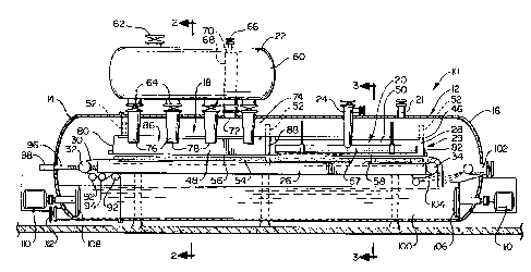
With reference to Figure 1, the apparatus 10 of the
present invention comprises an elongate main pressure
vessel 12 which remains pressurized throughout the
operation of the apparatus 10. The vessel 12 has a
forward end 14 and a rear end 16. and further has at its
forward portion a dewatering area 18 and at a rear
portion a washing area 20. At the dewatering area 18,
there is a head-box 22 mounted above the pressure vessel
12 and containing a pulp slurry which is supplied into
the dewatering area 18. At the rear portion of the
pressure vessel 12 there is a water inlet 24 which
directs the wash water into the washing area 20. Also.
there is provided a pressure inlet 21 by which a
pressurized gaseous medium (e.g. air, steam, or a
combination thereof) can be directed into the vessel 12
from a pressure source.
14
The apparatus 10 can be considered as having two
main operating sections that cooperate with one another
to accomplish the major functions of the present
invention. First, there is a conveying and pressure
differential table unit 26, and second there is the
enclosure frame unit 28. The table unit 26 and the
enclosure frame unit 28 can be considered functionally as
comprising a table assembly 29. The conveying and
pressure differential table unit 26 will, for
convenience, simply be called the "table unit "26. The
table unit 26 comprises an endless foraminous conveying
belt 30 that travels around front and rear end rolls 32
and 34, respectively. The table unit 26 also comprises
a support structure 36 that has two longitudinally
extending left and right tubular side beams 38 and 40.
between which extend an upper horizontal perforate plate
42 and a lower imperforate plate 43 (see Figure 6). (The
term "left" and "right" are taken from a rear location
looking forwardly. See Figures 2 and 3.) These two
plates 42 and 43 extend horizontally between the side
beams 38 and 40 and are connected thereto, and these
plates 42 and 43 define front and rear variable pressure
chambers 44 and 45 in the operation of the present
invention.
The enclosure fzame unit 28 has a main frame
structure 46 which in terms of function can be considered
as having a forward mat forming frame section 48 and a
rear wash water enclosure frame section 50. For
convenience of manufacture and operation, these two frame
sections 48 and 50 are simply made as a single unitary
frame structure 46. The frame structure 46 is mounted by
- 15 -
2~'~~'~~
a plurality of hydraulic or pneumatic lifting jacks 52 so
that the frame structure 46 can be raised a moderate
distance above the upper run of the belt 30 of the table
unit 26 or lowered into engagement with the belt 30 and
also side portions of the support structure 36.
(b) General Descr iption of the Operation
With the foregoing general description in mind, there
will now be a brief description of the overall operation
of the present invention. Initially, the interior of the
vessel 12 is pressurized, and the jacks 52 are used to
lower the frame structure 46 onto the table unit 26. The
table unit 26 and the frame structure 46 are arranged so
that When the frame structure 46 is in its lower belt -
engaging position, the forward mat forming frame section
48 forms a peripheral enclosure entirely around the
dewatering area 18, and at the same time the rear wash
water enclosing frame section 50 forms a peripheral
enclosure entirely around the.dewatering area 20.
The frame structure 46 is shown in Figure 1 in
its raised position, and is shown in Figures 2 and 3 in
its lower position engaging the table unit 26. To
initiate the operation of the apparatus 10, with the
enclosing frame structure 46 in its lower position, the
pulp slurry is directed from the headbox 22 onto that
area of the belt 30 that is at the dewatering area 18 and
enclosed by the forward mat forming frame section 48.
When there is an adequate depth of pulp slurry over the
belt portion in the dewatering area (e.g. approximately
an inch depth or possibly moderately greater), then the
is
apparatus 10 is operated in a manner to create a pressure
differential between the space above the pulp slurry
Layer (which is the pressure level within the pressure
vessel 12) and the forward variable pressure chamber 44
S defined by the forward portions of the horizontal plates
42 and 43. This pressure differential causes the liquid
in the slurry on the belt 30 in the dewatering area 18 to
be forced from the pulp into the forward low pressure
chamber 44, from which the liquid is removed through the
left tubular side beam 38. (The precise apparatus and
method by which this is accomplished will be described
more fully later herein.)
As the liquid is being pushed from the mat into
the forward low pressure chamber 44, additional pulp
slurry material is being discharged into the dewatering
area 18 until a desired depth is reached (e.g. between 5
to 10 inches. depending upon the consistency or the pulp
slurry and desired basis weight of the stock and other
operating conditions). When the pulp slurry in the
dewatering area 18 has been exposed to the pressure
differential for a sufficient length of time so that an
adequate percentage of the water is removed, the
apparatus 10 is operated in a manner to be described
hereinafter to equalize the pressure between the forward
low pressure chamber 44 just below the pulp mat S4 and
the overall high pressure within the vessel 12. With
this being done, the only force on that portion of the
belt 30 in the dewatering area 18 is the weight of the
pulp mat S4.
Then the frame structure 46 is raised so that the
lower edge S6 of the frame structure 46 is above the
- 17 -
level of the pulp mat 54 that has been formed on the belt
30 at the dewatering area 18. Typically, in this ffirst
embodiment this mat after dewatering will have a
consistency of between about fifteen (15%) percent to
twenty five (25%) percent, depending upon a number of
factors. (Hy way of background explanation. as used
herein, the term "consistency" is a percentage value
equal to the percentage of wood pulp by weight to the
total weight of the slurry. In other words. if the
slurry is 98% liquid, which liquid includes the solids
dissolved or contained therein. and only 2% pulp, then
this would be 2% consistency.)
Then the conveying belt 30 is operated to move
rearwardly in a manner to move the pulp mat 54 from the
dewatering area 18 rearwardly to the washing area 20. at
which time the belt 30 is stopped. Then the frame
structure 46 is lowered into place, so that the rear wash
water enclosing frame section 50 encloses the pulp mat 54
in a close peripheral fit. With this being accomplished.
the water inlet 24 is operated in a manner to direct wash
water into the washing area 20. More specifically, there
is a distribution pipe 57 and a perforate water
distributing plate 58 that extends horizontally entirely
across the rear frame section 50, so as to be positioned
a short distance above the top surface of the pulp mat
54, and also has enclosing side walls. The washing water
from the inlet 24 distributes itself over this perforate
plate 58 and then drops onto the top surface of the pulp
mat 54 in a manner to cause little impact thereon.
At the same time that the wash water is being
discharged into the washing area 20, an additional
1~ ~ 2~~fii~.~
quantity of pulp slurry is being discharged from the
headbox 22 into the dewatering area 18 in the same manner
as described earlier herein. This is done while the
above atmospheric pressure is maintained in the vessel
12. Also. shortly after the wash water is being directed
into the washing area 20 and the pulp slurry is being
discharged into the dewatering area 18, the apparatus is
operated (in a manner to be described more specifically
hereinafter) to reduce the pressure in both low pressure
chambers 44 and 45. (As described previously, this
reduction of pressure in the forward chamber 44 has the
effect of causing the liquid in the pulp slurry in the
dewatering.area 18 to flow downwardly into the forward
low pressure chamber 44.)
The lowering of the pressure in the rear low
pressure chamber 45 causes a "displacement washing" of
the liquid that remains in the pulp mat 54. More
specifically, the greater pressure above the level of
wash water on top of the pulp mat 54 in the washing area
20 causes this layer of wash water to press downwardly
into the mat 54 and displace the liquid (commonly called
"blank liquor") that is in the pulp mat 54. When the
black liquor liquid in the pulp mat 54 is substantially
entirely displaced. then the pressure in the rearward low
pressure chamber 45 is increased so that it becomes equal
with the overall pressure within the pressure vessel 12.
At that time, the washing of the pulp mat 54 in the
washing area 20 is accomplished. .
After the simultaneous washing and dewatering
operations are accomplished, then the conveyor belt 30 is
again moved rearwardly so that the rearwardly positioned
- 19 -
pulp mat 54 that has been washed is moved on for further
processing, while the second pulp mat 54 which has been
newly formed at the dewatering area I8 is moved
rearwardly into the washing area. Then the same overall
process is repeated as described immediately above.
It is to be recognized that the simultaneous
dewatering and washing operations on the two pulp mats 54
at two different areas axe coordinated so that each
operation takes approximately the same time. For this
reason, it may be that the amount of dewatering that is
accomplished in the dewatering area 18 may be reduced
moderately so that it would take about the same tip to
'form the pulp mat 54 at the dewatering section 18 as it
would to wash the previously formed pulp mat 54 that is
I5 being washed at the washing area Z0. For example. it
might be that it would be quite practical to dewater the
pulp mat 54 in the dewatering zone to a 25% consistency,
but that this would take longer than it would take to
cause a simultaneous washing operation of such a pulp
mat. To optimize the timing, it might be better to, for
example, cause the pulp mat 54 to be~formed and dewatered
in the dewatering zone 18 to only a 20% consistency, and
leave some additional dewatering to be done in the
washing zone before applying the wash water.
At this point, it should be noted that the only
times the pulp mats 54 are moved by the belt 30 are
during the periods when the pressures above and below the
pulp mats 54 are equalized, so that the only force on the
belt 30 pressing it against the stationary perforate
plate 42 is simply the weight of the pulp mats 54: Oa
the other hand. while the pulp mats 54 are stationary.
- 2~ - ~~'~r~~.~
the pressure differential applied across both of the pulp
mats 54 can be relatively large. One of the limitations
in prior art apparatus which accomplishes dewatering
and/or washing on a con tinuously moving f oraminous belt
is that the pressure differential cannot be so large so
that the frictional engagement between the conveyor belt
and the belt support is so great that the resisting force
provided by the friction is too great for practical
operation. This same disadvantage does not apply in the
IO operation of the present invention. On the contrary, the
limitation on the amount of pressure differential would
depend primarily upon the ability of the support
structure to withstand such pressure differential while
the belt is stationary. and would also depend upon the
optimized operating conditions for accomplishing the
dewatering and washing. zt is presently contemplated
that the pressure differential in the dewatering zone 18
could be in the range of 50 to 150 pounds per square
inch, and could possibly be as high as 300 pounds per
square inch or higher. In the washing area 20, it is
contemplated that the pressure differential across the
ma t during washing could be as high as 50 to 150 pounds
per square inch, and could conceivably be as high as 300
pounds per square inch or higher. This will vary,
depending upon further analysis, upon the nature of the
pulp being processed, and other operating conditions.
Higher than 300 pounds per square inch pressure
differential would be utilized. for example, when the
invention is used directly after a continuous digester
and the pulp slurry is fed into the apparatus 10 under
full digester pressure.
21 -
c. More Detailed Description of the Invention
The headbox 22 is, or may be. of itself, of more or less
conventional design. As shown herein, the headbox 22
comprises a containing structure 60 having an upper inlet
valve 62 and a plurality of lower outlet valves 64.
There is an upper pressure relief valve 66 and a vest
pipe 68 having an open upper end 70 at the upper part of
the container 60 and having an open lower end 72 opening
to the interior chamber 74 of the pressure vessel 12. As
can be seen in Figure 2, each of the outlet valves 64
leads into two related branch pipes 76 that discharge the
pulp from the laterally spaced lower ends thereof 78 into
the enclosure defined by the forward mat forming frame
section 48 of the frame structure 46. As shown herein.
there are four such outlet valves 64 and a total of eight
branch pipes 76 to provide a proper distribution of the
pulp slurry into the dewatering area 18.
The frame structure 46 has an overall rectangular
configuration with an open top and an open bottom. More
garticularly, there are front and rear end walls 80 and
82, respectively, left and right side walls 84 and 86,
respectively, and an intermediate transverse wall (a'
portion of which is shown at 88). It can readily be seen
that the intermediate wall 88 divides the frame structure
46 into the front and rear frame sections 48 and 50 so as
to define the perimeters of~ the dewatering area 18 and
the washing area 20. Further, it can be seen that the
material containing surface of each of the walls 80
through 88 has an upper inward taper. This enables the
._~, _. .
- 22 -
frame 46 to be moved upwardly without disturbing the mat
54 that has been formed. Further, with regard to the
rear frame section 50, this permits the frame section 50
to be lowered onto the already formed mat 54 without
disturbing the side edges. Further, each of the walls 80
through 88 is provided with a lower peripheral seal.
which is indicated at 90. This seal is or maybe of
conventional design.
To turn our attention now to the table unit 26.
the belt 30, as indicated previously, engages the front
and rear end rolls 32 and 34. In addition, it engages
two idler rolls 92 and a guide roll 94. The front roll
32 can be adjusted forwardly and rearwardiy by two screw
adjustment devices 96 that engage a mounting bearing
housing on opposite sides of the front roll 32. An
adjustment cylinder or motor 98 is provided for each
screw 96, and each is positioned outside of the pressure
vessel 12. Since these adjustment devices 96 are already
well known in the prior art. these will not be described
further herein. The rear roll 34 is a drive roll, and
this is powered by a suitable hydraulic motor. which for
ease of illustzation is not shown herein.
Also, at the end of each processing cycle. when
the upper run of the belt 30 is moved rearwardly, the
rearmost pulp mat 54 is simply directed over the belt 30
at the end of the rear drive roll 34 to drop into a lower
repulping chamber 100. As the mat 54 is discharged off
the rear drive roll 34, it is sprayed on the back side by
a dilution spraying device 102 and on the front side by a
doctor spraying device 104. In the repulping chamber
100, there are rear and forward repulping agitators 106
- 23 - ~~~~~~.)
and 108 that are driven by respective motors 110 to
agitate the pulp and cause it to mix with~the dilution
liquid. The reconstituted pulp then can be discharged
through a forwardly positioned valve 112.
To describe the conveying support structure 36.
reference is now made to Figure 6. As discussed
previously, this support structure 36 comprises left and
right tubular beams 38 and 40 which are conveniently made
with a cylindrical cross-section. Also, as discussed
previously there is an upper horizontal perforate plate
42 and a lower imperforate plate 43. The perforate plate
42 extends between uppermost portions of the tubular
beams 38 and 40 and has a plurality of closely spaced
relatively small through openings 114. The upper run of
the conveyor belt 30 rests directly on the upper
perforate plate 42. The lower imperforate plate 43 is
positioned a short distance downwardly from the upper
plate 42, and fixedly attached (e.g. by welding) as a
fluid tight connection to the left and right tubular
beams 38 and 40.
The particular section of the support structure
36 shown in Figure 6 is at the forward dewatering zone
18, and it will be noted that the left tubular beam 38
has a plurality of openings 116, which communicate with
the chamber 44 defined by the upper and lower plates 42
and 43. Positioned within this chamber 44 is a plurality
of transversely extending support spacing bars 118.
These support spacing bars 118 are of a sufficient width
(e.g. possibly made of steel an eighth of an inch to a
quarter of an inch thick) to provide structural support
and yet leave sufficient open space for the liquid to be
' . _ ,:.,~;:a~:~ ~ .
- 24 -
2~'~~~1~
drawn through the belt 30 and through the plate openings
114 into the chamber 43. It should be noted that the
rather substantial load imposed upon the plates 42 and 43
are what can be considered as compression loads tending
to push these two plates together. In other words. the
area above the plate 42 and below the plate 43 are
exposed to the greater than atmospheric pressure within
the tank 12, while during certain phases of the
operation, there is a reduced pressure (e.g. in the
IO preferred arrangement atmospheric pressure or near
atmospheric pressure) in the chamber 44. The spacing
bars 118 are of sufficient strength and are spaced at
sufficiently close intervals to withstand these
substantial compression loads. Also, the openings 116
are aligned to communicate to the spaces between the
spacing bars 118. These openings 116 lead from the
forward low pressure chamber 44 into a passageway 120
def fined by the left beam 38. The support structure also
has a lower support plate 121 or the like to support the
lower run of the belt 30.
With reference to Figure 3, it can be seen that
in the washing section, the table unit 26 has
substantially the same overall configuration as shown in
Figure 6, with one exception, which is that the openings
122 leading from the rear low pressure chamber 45 lead
into a passageway 124 defined within the right tubular
beam 40. Thus, the liquid which is displaced from the
mat 54 during the washing operation passes into the rear
low pressure chamber 45 and through these openings 122
and into the passageway 124 provided by the right tubular
beam.
To describe now the manner in which the pressure
differential is accomplished in the low pressure zones 44,
and 45, it should first be understood that the pressure
in the main vessel 12 is maintained at a level higher
than atmospheric pressure. The medium supplying the
pressure within the vessel 12 can be air. steam or for
some applications possibly some other pressure generating
medium.
With reference to Figure 2, there is a pressure
differential device or apparatus 125 which comprises a
first pipe section 126 which connects directly with the
passageway 120 in the left tubular beam 38 and loads to a
control valve 128 that communicates with another pipe
section 130 that in turn leads to an atmospheric tank
shown schematically at 132. The control valve 128
controls the pressure in the pipe 126 so as to control
the pressure differential between the chamber 44 and the
inter for of the pressure vessel 12.
Also, there is another pipe section 140 leading
from the pipe section 126 through a valve 142 to a
further pipe section 144 that communicates directly with
the interior of the pressure vessel 12 through an opening
146. By closing the valve 128 and opening the valve 14Z,
this causes the pressurizing medium (e.g. usually air or
steam) in the vessel 12 to apply pressure into the pipe
section 126, through the passageway 120 and through the
holes 116 to the variable pressure chamber 44, thus
equalizing the pressure in the chamber 44 with the
pzessure within the vessel 12.
To describe the manner in which this pressurizing
apparatus 125 is operated, let it be assumed that it is
- 26 -
desired to have the pressure within the chamber 44 to be
the same as the pressure inside the main pressure vessel
12. In this instance, as indicated above, the valve 128
is closed, and the valve 142 is opened. However, if it
is desired to lower the pressure in the variable pressure
chamber 44, then the valve 142 is closed, and the valve
128 is opened.
A second pressure differential apparatus is
provided for the rear variable pressure chamber 45.
Since this second pressure differential apparatus is
substantially the same, in both structure and function.
as the first differential apparatus 125, there will not
be a detailed description of the same. Rather. it~will
simply be given like numerical designations, with an "a"
suffix distinguishing the corresponding components of the
second pressure differential apparatus. which is
designated 125a.
There will now be a more detailed description of
the precise mode of operation of the pressure
differential devices 125 and 125a relative to the overall
operation. As discussed earlier herein with regard to
the overall operation of the present invention, an
initial step is to lower the frame structure 46 onto the
table unit 26. At this time, since there is no pulp
slurry or mat on top of the conveyor belt 30 either at
the dewatering location 18 or at the washing location 20,
the pressures within the chambers 44 and 45 will be the
same as the pressure in the pressure vessel 12, since the
air, steam or other medium within the pressure vessel 12
can communicate freely with the two variable pressure
chambers 44 and 45 through the openings 114 in the upper
2' - 2~'~~~.~
perforate plate 42. At this time, the valves 128 and
128a both are closed, and the equalizing valves 142 and
142a may be left closed or open. However, at such time
as either of the valves 128 or 128a is opened to create a
pressure differential in their respective chambers 44 or
45, the appropriate valve 142 or 142a must be closed.
As described previously in connection with the
operation of the present invention, at the start of the
operation, the pulp slurry is directed onto that portion
of the belt 30 that is at the dewatering zone 18. When
an adequate level of pulp slurry (e.g. approximately one
inch or more) is deposited on the belt portion at the
dewatering section 18. the valve 128 is opened (and the
valve 142 is closed) to cause the forward low pressure
chamber 44 to be exposed to the lower pressure within the
pipe section 130. This creates a pressure differential
relative to the chamber 44 to cause the liquid ~in the
pulp slurry to flow through the conveying belt portion at
the dewatering zone 20 and into the low pressure chamber
44.
When the dewatering operation has been carried on
for the desired time to form a pulp mat 54 of the desired
consistency, then the valve 128 is closed, and the
equalizing valve 142 is opened. At that time, the low
pressure chamber 44 will be full of liquid removed from
the pulp slurry, and also the passageway 120. the tubular
beam 38. as well as in the pipe section 126, will be full
of liquid. That liquid will simply be brought to a
pressure equal to the pressure in pressure vessel 12, so
that there will be no net force on the upper run of the
conveying belt 30. except for that downward force exerted
28 20~~~.~
by the weight of the pulp mat 54 formed on the conveying
belt 30.
As indicated previously in the general
description of the operation of the present invention,
after the pulp mat 54 has been formed, and dewatered to
the desirable consistency, the frame structure 46 is
raised, and the conveying belt 30 is moved in a rearward
direction to move the newly formed pulp mat 54 to the
rear washing location 20. Then the frame structure 46 is
again lowered to be in engagement against the table unit
26, and the operation is con tinued as described
previously herein. Specifically, a second partion of
pulp slurry is deposited onto that portion of the belt 30
that is in the dewatering zone 18, and at the same time
the washing operation is started at the washing area 20.
(It will be recalled that it was mentioned earlier that
under certain circumstances it may be desired to
accomplish the f final part of the dewater ing in the
washing area 20, in which case the wash water would not
immediately be applied directly to the upper surface of
the mat 54 at the washing area 20, but the dewatering
would occur for a short period of time to simply remove
additional liquid from the mat 54 at the washing area 20.
Then the washing water would be applied.)
With a newly formed mat 54 being located at the
washing area 20, and with the pulp slurry being deposited
on the belt portion at the dewatering area 18, the
pressure differential is now applied to both low pressure
chambers 44 and 45. The method of causing the pressure
differential in the zone 44 has been just described
above, and the same method would be used in causing the
2~7~1~.
- 29 -
pressure differential at the rear low pressure chamber
45, except that the liquid collected in the rear low
pressure chamber 45 is directed into the right tubular
beam member 40. Accordingly, a description of this will
not be repeated herein.
To describe another facet of the present
invention, reference is now made to Figures 4 and 5. For
convenience of manufacture and maintenance, the pressure
vessel 12 is made as two sections, namely a main rear
section 12a (See Figure 4), and a smaller front section
12b (See Figure 5). The headbox 22, the wash water inlet
24, and the frame structure 46 are all mounted to the
main rear pressure vessel section 12a. Further, the
dilution spraying device 102 and the rear agitator 106
are mounted in the rear vessel section 12a. Appropriate
support members 150 are provided at spaced locations
within and along the length of the pressure vessel
section 12a to provide support for the support structure
36 of the table unit 26.
The table unit 26 has its forward end mounted in
the front housing section 12b (See Figure 5) , and the
aforementioned front and rear rolls 32 and 34, the idler
rolls 92, the guide roll 94 and the screw adjustment
devices 96 are all mounted in the forward pressure vessel
section 12b. The forward agitator 108 with its
associated motor 110, and also the forward discharge
valve 112 are mounted in this vessel section 12b. The
two pressure differential devices 125 and 125a are also
mounted to the forward housing section 12b, but are not
shown in Figure 5 for convenience of illustration.
_ 3Q _ 2~'~~3.~~
The entire forward pressure vessel section 12b
and the table unit 26 are carried by a suitable temporary
mobile support vehicle 152 into the interior of the main
pressure vessel housing section 12a. When the table unit
26 has its major portion within the rear pressure vessel
section 12a, then the mobile support vehicle 152 is
removed, and other means can be used to support the
forward pressure vessel section 12b to complete the
rearward movement of this vessel section 12b. When the
two pressure vessel sections 12a and 12b abut one
another, they can be joined by appropriate means at the
location of their matching adjoining flanges 154 and 156.
d. Description of the Second Embodiment
A second embodiment lOc of the present invention
is shown in Figure ?. This second embodiment is
substantially the same as the first embodiment, except
that instead of using the pulp agitators 106 and 108, the
pulp mat 54 from the washing section is directed into a
feed screw section 158 that directs the pulp through a
conduit 160 to a discharge location for further
processing.
e. Description of the Third Embodiment
Figure 8 illustrates a third embodiment lOd of
the present invention. The apparatus shown in Fig ure 8
is quite similar to that shown in Figure 3, and for
convenience, components in this third embodiment which
are similar to the components shown in Figure 3 will be
- 31 - ~~'~611~
given like numerical designations with the "d"
distinguishing those of this third embodiment. As
presently described, this apparatus shown in Figure 8 is
added as a third processing area or station to be
positioned rearwardly of the washing area 20, and this
third processing area is used to impregnate the pulp mat
54d with a suitable liquid or liquid chemical or the
like, for example as part of a bleaching treatment.
treatment with oxygen or chlorine, etc. Further, there
could even be a fourth processing area where the
treatment medium (e.g. the bleaching agent) is removed by
a subsequent washing operation, as described previously
herein.
To return to the description of the apparatus
shown in Figure 8, there is the pressure vessel 12d which
is a rearward extension of the previously described
pressure vessel 12. There is a liquid inlet 24d, and
there is a rear frame section 50d which could be part of
.the frame section 46. or possibly a totally separate
frame section.g There is a table unit 26d which could
simply be a rearward extension of the previously
described table unit 26, and also the pressure
differential device 125d.
In the operation of the third embodiment, the
pulp mat 44d is moved into the processing area, and the
.liquid treatment medium is discharged through the inlet
24d and deposited onto the pulp mat 54d, in much the same
manner as the washing liquid is deposited, as described
herein relative to Figure 3. Then the pressure
differential is applied so that this liquid treatment
medium is forced to flow into the pulp mat 54d and
32
displace the previous liquid medium therein (which in
this particular instance would be the wash watex that is
forced out) .
Thereafter, the frame section 50d is raised, and
S the conveyor 30d operated to move the pulp mat rearwardiy
to a further processing location or to a discharge
location.
In Figure 9 there is shown a modified version of
the conveying belt 30, and this modified version will be
designated 30e. It will be recalled that the lower
peripheral edges of the frame section 46 are moved
downwardly to engage the upper run of the belt 30, and
the lower side edges of the frame section 46 engage the
beams 38 and 40. In this alternative arrangement, the
conveying belt 30e has certain portions thereof made
imperforate, and these imperforate sections are made in
elongate strips so that these match the lower sealing
edges of the frame section 46. Thus, the lower sealing
edges of the frame section 46 engage these elongate
imperforate strip portions of the belt 30e, so that there
is a liquid type seal made between those imperf orate
portions of the belt 30e and the matching lower sealing
edge portions of the frame section 46e. In the drawing
of Figure 9, the longitudinally extending edge
imperforate strip portions are designated 170, and the
transverse imperforate sections are designated 172.
Various means could be used to form these imperforate
strips 170 - 172. For example. neoprene rubber or some
suitable resin (silicone) that would harden and yet
permit some moderate degree of flexibility could be used.
33
f. Description of the Fourth Embodiment
The fourth embodiment of the present invention
will now be described with reference to Figures 10
through 30. This fourth embodiment is similar to the
first three embodiments in that there is a pressure
vessel enclosing the main operating components, a table
unit having a conveyor and a table portion to provide a
pressure differential, and a moveable enclosure frame.
However. this fourth embodiment differs from the
prior three embodiments in several major respects.
First. the dewatering and the washing of the pulp is
accomplished sequentially at the same processing
location. Second, to enhance the dewatering and washing
process, there is provided a dewatering/washing plate
assembly which presses against the top of the pulp mat to
aid in the dewatering, and also assists in accomplishing
the washing. Third, there is added a wash water
recycling system to accomplish a plurality of
countercurrent washing steps. Fourth. there is a
different discharge system by which the processed pulp
mat is removed from the pressure vessel. In addition to
the differences noted immediately above, there are other
differences or modifications which will become apparent
from the following detailed description.
With reference first to Figures 10 and 11, the
fourth embodiment 210 has (as in the first embodiment) a
main pressure vessel 212 with front and rear ends 214 and
216. There is a single processing area 218 which is both
a .dewatering and washing processing area and which
- 34 -
occupies a substantial portion of the pressure vessel
2I2.
As in the first embodiment, there is a head box
220 for the pulp slurry to be processed, a pressure inlet
22I, and also a manifold system 222. Positioned within
the pressure vessel 212 there is a conveying and pressure
differential table unit 224. As will be disclosed more
fully later herein, this table unit 224, in conjunction
with other components, accomplishes both the dewaterirg
and washing operations sequentially.
Also positioned within the pressure vessel 2I2 is
an enclosure frame 226 which performs a function similar
to the enclosure frame 28 of the first embodiment to
contain the pulp slurry and wash water. in a manner that
there is a sealed area to accomplish the dewatering and
washing. In terms of function. the table unit 224 and
the enclosure frame 226 can be considered to function as
a table assembly 227 that contains the pulp slurry and
accomplishes certain processing functions.
As a new feature in this fourth embodiment. there
is a dewatering/washing plate assembly 228 which, during
the latter part of the dewatering operation and during
the washing' sequence, is pressed against the top surface
of the pulp slurry being processed. This plate assembly
228 has been found to significantly improve the operation
of the present invention, and its~function will be
discussed in more detail later herein.
Just above the plate assembly 228 is positioned a
wash water dispensing assembly 230 which comprises a
plurality of dispensing troughs 232. This trough
assembly 230 provides a convenient means for dispensing
.. ....... -W~~::....
35 207~~.~
the wash water sequentially onto the plate assembly 228
d ur ing the wash cycl es .
As in the first embodiment, the table unit 224
comprises a conveyor belt 234 which engages front and
rear rolls 236 and 238. The upper run of this conveyor
belt 234 extends along the top portion of the table unit
224 and functions in a manner similar to the conveying
belt 30 of the first embodiment.
At the rear end of the conveying belt 234 there
is a pulp discharge assembly 240 which, as indicated
above, functions somewhat differently than the discharge
mechanism of the prior embodiments. In general. this
discharge assembly 240 receives the processed pulp mat
directly from the conveying belt 234 and moves the pulp
I5 mat through a discharge passageway at which the pulp mat
forms a substantial seal. Then as the pulp mat is moved
into a discharge area. pressurized gas (e.g. air or
steam) from inside the vessel 212 moves the pzocessed
pulp material through a valve to a location outside the
pressure vessel 212. This will be described in more
detail later herein.
There now will be a more detailed description of
this fourth embodiment. With reference to Figures 14
through 16. the headbox 220 is made in the form of a tank
to contain pulp at a relatively high pressure which is
moderately greater than the pressure within the main
pressure vessel 212 due to it's hydrostatic head only.
There is a pulp inlet pipe 242 having an upper inlet end
244 and a lower outlet end 246 located within, and at the
lower part of, the headbox 220.
36
As will be described hereinafter, the pulp in the
headbox 220 is discharged rather quickly in a batch into
the processing area 218. During the operation of the
apparatus 2I0, wood pulp is directed substantially
S continuously into the headbox 220 and reaches an upper
level 248, and drops to a lower level 250 immediately
after a batch discharge of the pulp. The lower end 246
of the pipe 242 is positioned moderately below the lower
level 250 so that splashing of the incoming pulp slurry
and a mixing with air is minimized.
There is a pressure equalizing conduit 252 which
has an end elbow 254 that extends into the headbox 220
and has an end opening 256 that is located above the
upper pulp level 248. This equalizing tube 252 connects
to a fitting 258 that leads into the interior of the main
pressure vessel 212. Thus, as the liquid level of the
pulp slurry in the headbox 220 changes, gas is permitted~
to flow between the headbox 220 and the interior of the
main pressure vessel 2I2 to equalize the pressure in the
headbox 220 and the interior of the vessel 212.
The manifold system 222 has a central inlet 260
that connects to a lower outlet valve 262 of the headbox
220. This inlet 260 leads into a main trunk section 264
that extends forwardly and rearwardly from the inlet 260,
with the forward and rear ends of the trunk section 264
leading into two branch lines 266, with each branch line
266 leading into a respective sub-branch 268. The sub-
branches 268 each comprise lines 270 that are in turn
connected through respective valves 271 to outlet
members 272, each of which is positioned at the side of
_ . _ ~"".~... .
- 37 -
the pressure vessel 212 a little above the tap of the
enclosure frame 226.
More particularly, as can be seen in Figure 11,
the outlet end 274 of each of the members 272 is
positioned moderately above the edge of the frame 226 so
as to be slightly outward of the vertical inside surface
276 of the enclosure frame 226. Also, this outlet 2?4 is
positioned laterally just a short distance outside of the
lateral edges of the dewatering/washing plate assembly
228. Thus, the pulp slurry is able to be discharged from
the outlets 274 onto the table unit 224 within the area
of the enclosure frame 226. The positioning of the
outlet 274 permits the plate assembly 228 to be lowered
downwardly to fit within the enclosure frame 226 and
press against the pulp on top of the table unit 224. As
can be seen in Figures 10, 12 and 13. the pulp outlets
274 are positioned in pairs on opposite sides of the
pressure vessel 212 and spaced longitudinally at even
intervals for proper distribution of the wood pulp onto
the table unit 224:
The enclosure frame 226 comprises two
longitudinally aligned side members 278 that extend along
the lateral edge portions 280 of the belt 234, and two
transverse members 282 that join the front and rear ends
of the side me~rbers 278. These members 2?8 and 282 form
a rectangular enclosure frame that defines the processing
area 218.
As in the first embodiment, this enclosure frame
226 can be raised or lowered, and to accomplish this.
there is provided a set of four hydraulic jacks 284. The
upper surfaces 286 of the side and end members 278 and
- 38 _
2~'~b~~.
282 are slanted downwardly and inwardly toward the
processing area 218 so that if any of the wood pulp
happens to splash onto the surface 286, it will tend to
flow into the enclosed processing area 2I8.
The aforementioned table unit 224, as can be seen
in Figure 17, in addition to comprising the conveyor belt
234 further comprises a pressure differential plate
assembly 288 comprising an upper plate 290 and a lower
plate 292 which are joined and sealed at their edges by a
IO perimeter strip 294. The upper and lower plates 290 and
292 each have a planar. rectangular configuration, and
are spaced a short distance vertically from one another
to provide an enclosed chamber 296 that extends through
substantially the entire area of the plate assembly 288.
These plates 290 and 292 extend beneath the entire
processing area 218. and the side and end edges of these
plates 290 and 292 are positioned just below the
perimeter frame members 278 and 282.
The upper plate 290 is formed with a plurality of
vertical through openings 298 positioned at equally
spaced intervals over substantially the entire surface of
the upper plate 290. The upper run of the conveying belt
234 rests on top of the plate 290 and the liquid from the
pulp mat on the belt 234 flows through the openings 298
and into the chamber 296 between the plates 290 and 292.
In this fourth embodiment, the spacers between the upper
and lower plates 290 and 292 are conveniently provided in
the form of round wires 299 that extend transversely
(e. g. about 1/4 inch in diameter) across the entire width
of the table unit 224, with these wires 299 being spot
welded in place at longitudinally spaced intervals along
_ . _ . . ., . . __..,:_::;::~:
- 39 -
the entire length of the plate assembly 288. The wires
299 divide the chamber 296 into a plurality of
transversely extending subchambers into which the
openings 298 lead.
To provide the pressure differential in the table
unit chamber 296 and also to remove the liquid collected
in this chamber 296, there is provided a plurality of
longitudinally extending tubes 300 that are positioned
immediately below the lower plate 292 of the table unit
224. The lower plate 292 rests directly on the tubes 300
and each tube 300 is provided with a plurality of spaces
through openings 304 that are aligned with and directly
adjacent to corresponding openings 302 in the lower, plate
292. The plate and tube perimeter edge portions around
these openings 302 and 304 are joined by a
circumferential weld 306 that forms a fluid tight and gas
tight seal around each pair of aligned opening 302 and
304. These tubes 300 are spaced laterally across the
processing area so that these openings 302 and 304
provide adequate flow paths throughout the entire area of
the chamber 296.
The rear ends of the tubes 300 are (see Figure
18) formed with right angle sections 308, each of which
extends laterally and connects with a related outlet
fitting 3I0 (see Figure 11) mounted in the wall of the
vessel 212. As shown in Figure 11, each fitting 310 is
connected through a line 312 to a related outlet valve
314 which leads through a line 316 to a selected one of
several tanks (to be described hereinafter). Also, one
line 312 that is connected to the tube 300 nearest the
centerline of the main pressure vessel 212 is connected
- 40 -
to an equalizing valve 3I8 which leads back into the
interior of the vessel 212 through a line 320.
Each of the valves 314 and the valve 318 is
operated in a manner similar to the valves 128 and 142 of
the first embodiment to either create a pressure
differential between the plate unit chamber 296 and the
interior of the vessel 212, or to equalize the pressure
in the chamber 296 and inside the vessel 312. Since this
function is described in detail in the description of the
first embodiment, this will not be repeated herein.
It is to be understood that the aligned openings
302 and 304 are positioned not only along the
longitudinally aligned sections of the tubes 300, but
also in the curved and right angle sections 308 so that
these openings pairs 302-304 are positioned throughout
substantially the entire suzface of the table unit 226.
To describe in more detail the dewatering/washing
plate assembly 228, this assembly comprises a main
horizontal rectangular contact plate 322 having a
peripheral side wall 324 extending entirely around the
side edges of the plate 322. This plate 322 is lowered
and raised by a set of four pistons 323. two of which are
shown somewhat schematically in Figure 11.
As can be seen in Figure 21, the contact plate
322 is formed on its lower side with a plurality of
longitudinally extending inverted "V" shaped grooves 326,
each groove 326 being formed by soaking surfaces 327 that
lead to an upper apex line or strip 328, and each pair of
adjacent grooves forming a lower ridge line or strip 330
where the adjacent sides of adjacent grooves meet one
another. The contact plate 322 is formed with a
.... ..
- 41 -
plurality of evenly spaced vertical through openings 332
extending along the length of each apex strip 328. Thus.
when wash liquid is placed on the top surface 334 of the
contact plate 322, the liquid flows through the openings
332 and into the grooves 326 at the location of the apex
strips 328.
At this point the function of the dewatering/
washing plate assembly will be described briefly, but
there will be a more detailed description of its
operation later herein. After the pulp slurry is
initially discharged from the headbox 220 and manifold
system 222 into the processing area 218 inside the
enclosure frame 226 (which is in its lower position), the
plate assembly 228 is lowered so that the contact plate
322 comes into contact with the upper surface of the pulp
slurry. At the same time, there is a pressure
differential between the interior of the vessel 212 and
the pressure differential chamber 296 so that the
pressure applied to the top of the contact plate 322 acts
to push the plate 322 downwardly.
The pressure inside the vessel 212, in addition
to pushing on the upper surface 334 of the plate 322,
also exerts pressure through the openings 332 to bear
directly against the pulp located at the opening 332.
The pressure on top of the contact plate 322 causes the
liquid in the pulp slurry to flow downwardly through the
conveyor belt 234, through the plate openings 302-304 and
into the pressure differential chamber 296 which is at
this time at a low pressure level.
After the dewatering operation is completed. then
the wash cycles begin. A first layer of wash liquid is
42 ~~~f?~~~
deposited on top of the contact plate 322, and this wash
liquid flows through the openings 332 downwardly through
the pulp mat to cause a liquid displacement washing
operation. (This will be described in more detail later
herein). At the completion of the washing cycles the
valves 314 and 318 are operated to equalize the pressure
in the pressure differential chamber 296 with the
pressure in the vessel 212, the dewatering/washing plate
unit 228 is raised, and the enclosure frame 226 is also
raised. Then the conveying belt 234 can be moved to move
the processed pulp mat through the discharge assembly 240
to a location outside of the pressure vessel 212.
To describe further the configuration and
operation of the contact plate 322, reference is now made
to Figure 28.. First, with regard to the dimension and
configuration of the contact plate 322, in one embodiment
which has been found to operate effectively, the diameter
of the openings 332 (indicated at "a") were made as 1/16
inch. The lateral spacing of these openings 332 from one
apex line 328 to another is 1/2 inch (indicated at "b" in
Figure 29) and the longitudinal spacing along each apex
line 328 is 1/2 inch. The total depth dimension of the
plate 322 (indicated at "c") is 1/4 inch. The width of
the apex line 330 (indicated at "d" in Figure 29) is 1/16
inch. The angle of slant of the surfaces 327 relative to
the horizontal was about 300 (indicated at ~e~ in Figure
29) .
It is to be understood, of course, that the
dimensions and angles presented above are given simply by
way of example of a contact plate 322 that has been found
to wor:c effectively, and these~could be varied. With
... . .. . .. _ ...-.
_ 2~'~6~1~
regard to the spacing and the diameter of the openings
332, the total cross-sectional area of these openings 332
should be great enough to permit an adequate rate of flow
of the wash liquid through the openings 332 and into the
pulp mat. Xet present analysis indicates that the size
of the opening 332 should be sufficiently small and the
spacing of the openings sufficiently great so that the
contact plate 322 had adequate area to maintain its
capability to enhance the dewatering operation.
It has been found that the use of this contact
plate 322 in the present invention enhances both the
dewatering and the washing operation. It was found
experimentally that when the pulp slurry was dewatered to
a certain consistency (in the order of about 20 to 25
IS percent) without use of the contact plate 322. further
dewatering was not accomplished, because as the pressure
differential continued to be applied, small air
passageways (or steam passageways, if steam is present in
the vessel 212) would form through the pulp mat. causing
a blow-by condition.
On the other hand when the pressure plate 322 was
used in the manner indicated above, it was found that the
dewatering process could be continued until (for the same
type of pulp slurry) the consistency of the pulp slurry
was raised to as high as 25 to 35 percent before further
effective dewatering could not be accomplished. The
physical phenomena which account for this improvement in
dewatering have not at this time been fully ascertained.
but it can be hypothesized that the pressure above the
plate 322 causing it to act as a pneumatic press
contributes to these improved results. Further the
_ ,~~ ..
2Q'~ 31~.
formation of the plate with slanted surfaces forming the
ridge and groove configuration could quite possibly have
functional advantages. Furtherr while the openings 322
serve the function of permitting the wash water to flow
through the plate 322 during the wash cycles, there is a
possibility that these holes 332 permitting gaseous
pressure to act directly against the pulp slurry surface
could contribute advantageously. However, regardless of
whether any of these hypothesis have any validity, it has
been found experi~:entally that (as indicated above) the
use of the contact plate 322 as described herein does
clearly improve the dewatering operation.
Also, as indicated above, the use of the contact
plate 322 enhances the wash operation. As will be
disclosed later in this text in the description of the
washing cycles. there is what is called a ~dilution
factor~ where during each washing operation a certain
portion of the black liquor that is removed from the pulp
mat is diluted by fresh wash water in the system. If a
ZO higher percentage of the black liquor is removed during
the dewatering process, then there is less black liquor
that needs to be removed during the washing grocess.
Thus, for the same dilution factor (which in the
preferred embodiment of the present invention is one) .
there is less black liquor to be removed during the
washing cycle and hence less wash water is needed for
each cycle of displacement washing cycle.
Attention will now be directed toward the
countercurrent liquid recirculating system of the present
invention. In the following description, a three stage
wash cycle is described. Further analysis has indicated
- 45 -
that this could advantageously be a five stage wash cycle
or possibly more than five wash cycles. However, for
ease of explanation, only three wash cycles are
described.
As indicated previously, there are three wash
water discharge troughs 232 which are utilized to
accomplish (in the present embodiment) three wash cycles.
Each trough 232 has the conf iguration of half of a
cylindrical shell, where the cylinder has been divided
along a plane coinciding with the center axis of the
cylinder. Each trough 232 is rotatably mounted about its
center axis of curvature 336 in a manner that by rotating
the trough 232 ninety degrees, the liquid in the trough
can be discharged by gravity flow onta the contact plate
322. Each trough 332 is fed by a respective inlet pipe
338. Each pipe 338 extends through the pressure vessel
and is connected to a respective feed tube 340.
With reference to Figure 22, there is shown
somewhat schematically the liquid flow system of the
present invention. There are three liquid receiving
tanks 342a, 342b and 342c. The first tank 342a is a
black liquor collection tank, and this receives the flow
from the outeraost and innermost sets of tubes 300a. The
liquid from this black liquor tank 342a is discharged
through a line 344 to an evaporating plant 346 or to some
other location for further processing. The lines
connecting the tubes 300a with the tank 342a are
designated 348a.
The second liquid collection tank 342b receives
the liquid flow from the collecting tubes 300b through
the lines 348b. The flow from this tank 342b connects to
. ...y:
- 46 - 2~~b~~
a return line 350b which in turn Leads to a related
trough 232a. The third liquid collection tank 342c
receives liquid from the collecting tubes 300c through
the lines 348c. The flow from this tank 342c connects
through a return line 350c to the trough 232b. There is
a fresh water supply line 350d that connects through a
valve 352 and leads into the third trough 232c.
Recirculating pumps 354b and 354c are connected in the
lines 350b and 350c, respectively.
with the liquid circulating system now having
been described with reference to Figure 22. let us now
turn our attention to the operation of this liquid
circulating system. As indicated previously, the process
of the present invention is started by initially
depositing a charge of waod pulpy having a consistency
of. for example, one. and one half to two and one half
percent onto the conveying belt 234 at the table unit
224, where it immediately begins to flow laterally to
form a layer. As soon as about one quarter to one half
of the charge of the wood pulp is deposited on the table
unit 224, the valves 314 connected to the collecting
tubes 300a are opened (with the equalizing valve 318
being closed at this.time? to connect these tubes 300a to
a low pressure area. which in this instance would be the
pressure at the black liquor collection tank 342a. This
causes the pressure in the table unit chamber 296 to drop
to create the pressure differential between the interior
of the vessel 2I2 and the lower pressure in the table
unit chamber 296, which in turn causes liquid to flow
from the pulp slurry into the chamber 296, and thence
into the collecting tubes 300a.
- 4? -
As ir.3icated previously, as~soon as the full
charge of pulp has been deposited on the table unit 224,
the dewatering/washing plate assembly 228 is immediately
lowered so that the contact plate 322 comes into
engagement with the upper surface of the pulp slurry. As
described previously, the pressure differential between
the interior vessel pressure above the plate and the
lower pressure below causes the plate 322 to press down
on the pulp slurry, and also gaseous pressure is exerted
through the openings 332. This enhances the movement of
the black liquor that is in the pulp slurry out of the
pulp, into the chamber 296 and thence into the tubes
300a.
Reference is now made to Figure 23 to illustrate
the sequence and operation of the dewatering and washing
cycles. This initial dewatering step is illustrated in
Figure 23 at the very left end of the figure at Station I
and II. To describe the format of Figure 24, there is an
upper line 356 which represents the location of the upper
surface of the wood pulp mat 358a at the completion of
the dewatering operation. The pulp slurry before
dewatering is illustrated at 358 at Station I. The level
360 represents the lower surface of the dewatered pulp
mat 358a which rests on the conveying belt 234.
Therefore, the area above the line 356 represents liquid
or pulp slurry above that level, while the area below the
line 360 is the area at which the liquid removed from the
wood pulp is located.
It can be seen at Station I at the very left end
of Figure 23 that the slurry 358 (with the black liquor
comprising from ninety seven and one half percent to
... ., . .. . ~ . ...: -..,.'tF:~_,'i.... ..
- 48 - 20'~~~.~
ninety eight and one half percent of the slurry) extends
a substantial distance above the level 356. As the
pressure differential is created, and also after the
pressure of the contact plate is applied, this liquor is
caused to be moved out of the pulp slurry, with this
removed black liquor being indicated at 362. This black
liquor is simply carried from the tubes 300a by the lines
348a into the black liquor tank 342a (See Figure 22).
When this initial dewatering step (shown
beginning at Station I) is just being completed (as
indicated at Station II of Figure 23), the trough 232a is
rotated ninety degrees to deposit the wash liquid in
trough 232a onto the top of the contact plate 322 (as
indicated at 364 Station III of Fig. 23). It can be seen
that this wash liquid in the trough 232a is received from
the tank 342b (See Figure 22) . Since the pressure
differential between the interior of the vessel 212 and
the chamber 296 remains, the wash liquid indicated at 364
is caused to move into the pulp mat and begin a
displacement Washing cycle.
At this point. let us pause to analyze the
content of the pulp mat and other factors and review
briefly some of the subject matter covered above with
reference to Figure 22. Let us assume, for ease of
calculation, that the consistency of the pulp mat after
dewatering is twenty five percent. Thus, the pulp mat is
seventy five percent liquid and twenty five percent pulp.
The pulp mat indicated at 358a (which is the pulp mat
immediately after dewatering is accomplished at Station
II) is thus one quarter wood pulp and three quarters
liquid, which liquid at this time is the original black
49 ~~~t3~~~
liquor liquid. It can be seen that the area between the
levels 356 and 360 has been marked off with two division
lines, defining three equal increments in the dewatered
pulp mat.
The deposit of wash liquid 364 from the tank 342b
is, in this particular example, four units, as shown at
Station III. At the same time there are (as indicated
above) four volumetric units in the pulp mat at 358a.
namely three units of black liquor and one unit of wood
pulp.
At Station I~, the wash liquid of 364 has moved
downwardly part way into the pulp mat, and it can be seen
that there is a mixing area developing at 366, where some
of the wash liquid 364 is mixing with some of the black
liquor (say one half unit of the f our added wash liquid
units). By the time four units of the wash liquid 364
have moved into the mat (as shown at Station V in Fig.
24) , it can be seen that the last portion of the black
liquor 362 in the mixing area 366 has been pushed through
the mat to the area 366a below the mat, and the wash
liquid 364 entirely permeates the wood pulp mat. During
this time. the mixed liquid at 366a and the last portion
of the black liquor indicated at 362a are deposited into
the black liquor tank 342a.
At this point. attention should be called to the
fact that the mixed portion of the liquid at 366a that is
deposited into the black liquor tanks is made up of one
unit of the original black liquor and one unit of the
wash water 364. This one unit of wash water is what is
in a sense "diluted" to the black liquor tank 342a as a
result of the three washing cycles, the first of which
,. ~, ,;: ,
. . . . . . ~ ..y..;._.:..:.e-:~
- 50 -
was described immediately above. As will become more
apparent as we continue with this description, this one
unit of "diluting" liquid is replaced by one unit of
fresh water. At the same time. there is one unit of wood
pulp that is being displacement washed. Thus, this gives
a dilution factor of one (i.e. one part pure water to one
part of wood pulp that is displacement washed).
To continue with our description of the process.
when the process has. reached the stage shown in Station
V, where the mixed liquid portion 366a has been moved
through the wood pulp mat. then the valves 314 leading
from the tubes 300a are closed, and the two valves 314
which connect to the tubes 300b are opened. At this
point the trough 232b is rotated ninety degrees and the
next four units of wash liquid 368 from filtrate tank
342b is deposited on the contact plate 322. The liquid
that is now being removed from the wood pulp is directed
to the collection tank 342b. (In Figure 24, this is
called the ~Filtrate One" tank). The reason for this is
that this filtrate from the tank 342b is (as will be
descrihed shortly hereinafter) countercurrently
circulated so as to be used as the wash liquid at 364 for
the first wash cycle. The timing of this operation of
the valves 3I4 to change flow from going to the black
liquor thank 342a to the filtrate one tank 342b depends
on how quickly the black liquor liquid has flowed from
the low pressure chamber 296 into the conduits 300a. As
the last of the black liquor liquid leaves the pulp mat
358a, there will still be some black liquor in the
differential pressure chamber 296 that desirably should
be directed into the tubes 300a. When this is
2~'~6~~~
- 51 -
substantially completed, then the valves 214 are operated
(as indicated above) to direct further f low into the
tubes 300b and thence to the filtrate one tank 342b.
As the second wash cycle progresses from Station
VI to Station VIII, it can be seen that four more units
of the second wash liquid 368 have moved into the pulp
mat, while the remaining three units of the first wash
liquid 364 inside the pulp mat and one unit of the second
wash liquid 368 have moved out of the mat into the
collection tank 342b. The removed second wash liquid is
indicated at 364a, and the removed mixed liquid is
indicated at 3?Oa. None of these units of the second
wash liquid 364a have been diluted into the black liquor
liquid tank 342a. As soon as the condition at Station
VIII is reached then the valves 314 leading from the
tubes 300b are closed, and the two valves 314 which
connect to the tubes 300c are opened and the third trough
232c is tilted so as to dump clean wash water onto the
contact plate 322, this wash water being designated 372.
ZO It can be seen from Figure 24 that this wash water 372 is
coming from the fresh water supply line 3508. Again, as
indicated earlier with regard to switching the valves 314
to cause flow to change from going to tubes 300a to tubes
300b, the timing will depend on how quickly the f low of
the second wash liquid 364a flows from the low pressure
chamber 296. After the valves 314 are so~operated, the
liquid that is then being removed from the wood pulp is
directed to the collection tank 342c icalled the
"Filtrate Two" tank).
To begin the third wash cycle illustrated in
Station IX to Station XI it can be seen that four units
_..~_...;::~-~..;~ .
_ 52 _ ~~~~)~ ~~3
of the third wash liquid 372 are deposited on the contact
plate 322 and are moved by pressure into the pulp mat.
The remaining three units of the second wash liquid 368
inside the pulp mat and one unit of this third (fresh
water) wash liquid 372 are moved out of the pulp mat into
the collection tank 342c (filtrate two tank), and these
are designated 368a and 374a. respectively.
This third wash cycle is continued until the four
units of fresh water 372 have moved totally into the pulp
mat 358, and the mixing zone 374 together with the last
portion of the water 368 have moved totally through the
mat. Now the valves 314 connected to the tubes 300c are
closed. At this time. the valve 318 is opened so as to
equalize the pzessure in the pressure differential
chamber 296 and in the vessel 2I2 so that there is no
further pressure differential. At this time. the
dewatering cycle and the three wash cycles have been
completed, and the pulp mat 358 is ready to be removed
from the processing area 216 and out of the pressure
vessel 212.
In the event that more than three wash cycles are
employed, then the apparatus 210 would be modified
accordingly. For example, for each wash cycle added
there would be an additional filtrate tank 342 in the
countercurrent recycling system. Also other
modifications could be made. For example, only two
troughs 232 could be used (or possibly two sets of two
troughs 232). Then after one trough 232 discharges its
wash liquid, it could be filled with the wash liquid from
an other filtrate tank 342. Two of the troughs 232 could
be used simultaneously to start one wash cycle, with the
53
two troughs being positioned on opposite sides of the
interior of the vessel 212. Or some liquid feed means
could be used other than the troughs 232.
In reviewing the entire process recited above
S with reference to Figure 23, it is apparent that the wash
water collected in the Filtrate One tank contains the
greatest amount of impurities, and that contained in the
Filtrate Two tank a lesser amount of impurities, with
the fresh water obviously containing the least amount of
impurities. Analysis will indicate that as this process
con tinues with batch after batch of wood pulp slurry
being processed, an operating balance will be achieved.
More specif ically, the pur ity of the liquid in the
Filtrate One and Filtrate Two tanks 342b and 342c will
remain substantially constant. The reason for this is
that at the completion of every set of three washing
cycles, one segment of fresh water has been added to the
Filtrate Two tank 342c, and one unit from the Filtrate
Two tank has been passed forward to the Filtrate One
tank. The reason for this is that the liquid from each
mixing zone is passed forward in the system toward the
black liquor tank and evaporator plant.
The next step is to remove the processed pulp mat
358 from the processing area 218 and also to a location
outside of the main pressure vessel 212. To accomplish
this, first the enclosure frame 226 and the
dewatering/washing plate assembly 228 are both raised,
and the belt 234 is moved in a forward direction to carry
the processed pulp mat 258 to the discharge assembly 240.
As can be seen in Figures 24, 25 and 26 the
discharge assembly 240 comprises a guide plate 380 that
- 54 -
~o~~~~.
has two side plates 382 that defines with the underlying
belt 234 an inlet 384 which has a height dimension
moderately greater than the thickness dimension of the
processed pulp 358. The plate 380 slopes very moderately
downwardly in a forward direction so that the passageway
386 leading frcm the inlet 384 and defined by the plates
380 and 382 and the upper run of the belt 234 tapers in
thickness in a forward direction. The effect of this is
that the pulp layer becomes squeezed to a moderate extent
in the passageway 386 as it progresses f orwardly.
The effect of so moving the pulp into the
passageway 386 is to substantially close the rear end of
the passageway 386 so that very little of the gas (e. g.
air or steam) within the vessel 212 passes through the
passageway 386. The passageway 386 at its rear end
terminates in a discharge passageway portion 390 having.a
substantially constant cross-sectional area. This
forward passageway section 390 leads into a discharge
chamber def fined by a discharge housing 392. This
discharge housing 392 has a generally frusto-conical
configuration. having at'its side a right side 394 a
smallex cross-sectional area and extending laterally
through the opposite side of the vessel 212 where it has
a more expanded area 395. At the outlet end, there is an
outlet valve 396. There is a gas pressure line 398
leading into the right end 394, and this line 398
connects through a valve 400 to an elbow 402 that leads
into the interior of the pressure vessel 212 at 404.
There is a doctor blade 406 having a forward edge
408 that removes the pulp mat from the belt 234. This
_ _..._ ..~.~v~.~: ~. .
_ ?~'~~3._~
3octor blade 406 defines the lower portion of the
aforementioned passageway 390.
In operation, when the dewatering and washing
cycle has been completed, the belt 234 is moved to in
turn move the forward edge of the pulp mat through the
entryway 384 and into the passageway 386. When the pulp
mat has moved forward to the extent that it substantially
encloses the passageway 386, then the valve 396 is
opened. thus reducing the pressure in the discharge
housing 392 to atmospheric. This enhances the movement
of the pulp mat toward the discharge housing 392. As the
pulp mat begins to be discharged from the forward
passageway portion 390 into the housing 392, then the
valve 400 can be selectively opened to cause the high
pressure gas in the vessel 212 to pass into the inlet
404, through the valve 400 and into the housing 392 to
assist in blowing the pulp material outwardly from the
housing 392 and through the valve 396. When the pulp mat
has been discharged, then these valves 400 and 396 are
closed.
To further describe the conveying belt 234.
reference is made to Figure 28. It can be seen that the
belt 234 has two edge strip portions 406 and two
transverse strip portions 408 that are made imperforate
in much the same manner as the belt shown in Figur a 9
These strips 306 and 408 engage the lower edge portions
of the enclosure frame 226 to make a seal. A second set
of strips 406 and 408 are also formed at the section of
the belt which in Figure 29 is at the lower run. Thus
of ter the dewatered and washed pulp mat is discharged
from the upper run of the belt 234, the lower fun moves
5~ - 2~ ~~~ ~~
to become the upper run of the belt for a second
dewatering and washing operation.
As indicated previously, one of the desirable
features of the present invention is that with the entire
process being performed within the pressurized vessel 212
(and in the first embodiment in the vessel 12), it
becomes more practical to operate with much higher
pressure differential across the pulp mat. This leads to
a number of advantages.
IO First. with a greater pressure differential being
applied across the pulp slurry and later the pulp mat.
the processing time is greatly reduced. For eaample. it
has been found experimentally, that during the dewatering
operation, if a pulp slurry of between one and one half
percent to two and one half percent consistency is
deposited on the table assembly 224 in the processing
area 218 to a depth of about 6 inches. when a pressure
differential of about 100 PSI is applied, and the contact
plate 322 utilized to press against the pulp slurry. the
dewatering is accomplished as quickly as in about 8
seconds.
Also, the washing operations can be accomplished
more quickly. For example, with a dewatered pulp mat of
about 1/2 inch thickness that has a consistency of abort
20 percent, with the wash liquid being deposited on top
of the plate 322, from the time the pressure differential
is applied to the tire a single wash cycle is completed.
the elapsed time is between about 1 to 3 seconds.
Another advantage is that with the relatively
high pressure in the vessel 212 (and also in the vessel
12 of the first embodiment) . the temperatures at which
_ _.....~-:::,~-
- 57 -
the dewatering and washing are accomplished can be
raised. One advantage of this is that the viscosity of
the black liquor decreases as the temperature increases.
Thus, the black liquor flows more easily through the pulp
slurry and pulp mat, and both the dewatering operation
and the oashi.~.g operation can be accomplished more
easily. Also, with regard to the washing operation, it
is believed that the higher temperature of the wash water
increases the effectiveness of the washing operation.
le A further advantage of operating at high
gressures within the vessels 212 (or the vessel 12 of the
first embodiment) is that there can (relative to certain
operations) be a savings in the energy used in the
overall wood pulp manufacturing process. For example.
before the pulp slurry is delivered to the apparatus of
the present invention, it is in a digester where it is
being processed at very high temperatures and pressures.
If this wood pulp is then, for example, moved to a
dewatering or washing area where the pressure and
temperature are much lower, then much of the heat energy
in this wood pulp is simply dissipated to the surrounding
atmosphere, largely in the form of the high temperature
water simply flashing off as steam. On the other hand.
if the pulp slurry is moved from the digester, while
maintaining this high pressure and temperature, to the
pressure vessel 212 (or the vessel 12 in the first
embodiment), less the heat energy (heat energy) is lost.
58
Further, after dewatering and wasbing, the black
liquor is commonly delivered to an evaporating area. In
the usual wood pulp manufacturing operation, it is
necessary to evaporate the black liquor to a higher dry
solid content to be able to. burn it in the recovery
boiler to recover chemicals that are reused.
With regard to the operating pressures~and
temperatures utilized in the present invention, to the
bes t knowledge of the applicant herein, the highest
pressure differentials used in the commercially practical
prior art dewatering and/or washing operations is no
greater than 10 PSI. In the present invention, the
pressure differential applied is greater than 10 PSI.
Beneficial results can be obtained to some degree in the
present invention with pressures in the vessel 12 or 212
as high as, for example. 20 PSI or 50,PSI. However. more
desirably, the pressures in the vessel 12 or 212 would be
at at least as high as 100 PSI or 150 PSI. It is
surmised that pressures as high as 300 PSI could also be
used, or even pressures up as high as 500 PSI. This
would possibly be more desirable particularly when the
wood pulp and removed liquid already is at a rather high
temperature and pressure at the previous processing
location (e.g. a digester), and the pulp slurry can be
moved into the apparatus of the present Invention without
loss of that heat energy already in the pulp slurry.
With the foregoing detailed description having
been completed, the overall operations of this fourth
embodiment will now be summarized. Initially, the vessel
212 is pressurized to an above atmospheric operating
pressure. Generally, the pressurized gaseous medium
.... .. .........;n;.~;4::r.~_ . .
59 -
within the vessel 212 is air, steam, or a combination of
air and steam. Al~o, desirably the temperature within
the vessel 2I2 is maintained at a level above ambient
temperature, this depending to some extent on operating
pressures and ot::~r factors.
A pulp slurry is directed through the pipe inlet
244 to flow into the headbox 220. Until the headbos 220
is filled to an adequate level (i.e. to the level 248 as
shown herein). Also the enclosure frame 226 is lowered
onto the table unit 224 and the plate assembly 228
remains in its.raised position. Then the valves 27I in
the manifold outlet members 272 are opened to cause the
pulp slurry in the headbox 220 to flow through the
manifold 222 and through the outlets Z74 onto the portion
of the upper run of the conveyor belt 234 that is within
the enclosure frame ZZ6. The pulp slurry typically would
have a consistency of one and one half to two and one
half percent. and at that consistency it would readily
flow across the table unit to form a substantially
uniform layer within the enclosure frame 226.
While the pulp slurry is flowing onto the table
unit 224, as soon as this pulp slurry has reached a
sufficient depth so that the dewatering process can begin
(typically in the order of 1 to 2 inch), the valve 314
that leads from the conduits 300a is opened to lower the
pressure in the variable pressure chamber 296 in the
plate assembly 288. At the same time, the equalizing
valve 18 is closed (or remains closed). This pressure
differential causes the liquid (i.e. black liquor) in the
pulp slurry to begin flowing through the foraminous
conveying belt 234 and through the openings 298 in the
.
- 60 -
2~'~~ii~.~
plate 290, thence into the chamber 296, from which the
liquid flows through the openings 304 that lead into the
conduits 300a. These conduits 300a in turn direct the
black liquor into the tank 342a. Typically the pressure
at the tank 342a would be atmospheric, and depending upon
the height of the liquid level in the tank 342, relative
to the height of the pressure differential chamber 296
the pressure differential across the pulp mat would be
close to the pressure difference between the pressure
vessel 212 and atmospheric pressure. This can vary,
depending on the circumstances.
As soon as the firs t batch of pulp slurry has
been completely discharged through the openings 274 into
the processing area 218, then the contact plate 322 is
promptly lowered onto the upper surface of the pulp
slurry. As described in more detail previously herein,
the gaseous pressure above the plate 322 pushes
downwardly on the plate 222 to cause it to press against
the pulp slurry and assist in the dewatering operation.
At the same time, gaseous pressure acts through the
openings 332 directly against the pulp slurry. This
pressure differential is maintained until the desired
amount of black liquor has been removed from the pulp
slurry to form the pulp mat. Typically. the dewatering
would be completed when the consistency of the pulp mat
has reached a level of between about 15 to 35 percent.
In general, it would be desirable to obtain as high a
consistency as possible, but this can vary, depending
upon various factors.
As soon as the dewatering step is completed. then
the trough 232a is tipped to deposit the first batch of
- 61 -
2~'~b~~.
Filtrate one wash liquid onto the top surface 334 of the
contact plate 322. The wash liquid flows through the
plate openings 332 and into the pulp mat to cause
displacement washing so that the black liquor remaining
in the pulp mat is moved out of the pulp mat and into the
pressure differential chamber 296. At such time as the
wash liquid has moved completely into the gulp mat and is
f lowing into the chamber 296, then the valves 314 leading
from the tubes 300a are closed off, and the valves 314
leading from the conduits 300b are opened to receive the
wash liquid. The washing cycles continue in the manner
described earlier herein with reference to Figure 24.
Since the description of these wash cycles has been dealt
with in detail previously herein, these will not be
described in any detail in this summary.
When the final wash cycle is completed, then both
the enclosure frame 226 and the contact plate 322 are
raised, the valves 314 that are open are then closed and
the equalizing valve 318 is opened to raise the pressure
in the table unit chamber 296 to the level in the vessel
212. With the pressure being so equalized. the only
force bearing on the upper surface of the conveyor belt
234 is the weight of the pulp mat. Then the conveyor
belt 234 is moved to cause the pulp mat to move into the
discharge assembly 240. Then the discharge assembly is
operated as described previously herein to move the pulp
mat out of the pressure chamber of the vessel 212.
It is to be understood, of course, that various
modifications could be made on the present invention
without departing from the basic teachings thereof. For
example. while the table unit 224 is provided witb an
- 62 -
endless conveyor belt 234 to remove the pulp material
from the processing area 218, within the broader scope of
the present invention, other pulp removal means could be
used. For example, after the enclosure frame 226 and the
plate assembly 228 have been raised, and after the
pressure in the variable pressure chamber 296 has been
equalized within the vessel 12 or 212, then a scope-like
member or an arm could be moved across the upper surface
of the table unit 224 to remove the pulp mat that has
been formed. Further, other mechanical devices or
removal techniques could be used to accomplish this
purpose.
Also, by way of further example, there could be
yet more processing stations or areas. Further. it is
conceivable that other operations could be performed at
the processing area 218. in addition to the dewatering
and washing.
Further. it is to be recognized that the above
possible modifications are given by way of example. and
yet other possibly modifications could be made without
departing from the basic teachings of the present
invention.
. .. .~. ... ..,.~..,. s..::r.'l .,-.:.:: ~ _ _ _