Language selection

Search

Patent 2076202 Summary

Third-party information liability

Some of the information on this Web page has been provided by external sources. The Government of Canada is not responsible for the accuracy, reliability or currency of the information supplied by external sources. Users wishing to rely upon this information should consult directly with the source of the information. Content provided by external sources is not subject to official languages, privacy and accessibility requirements.

Claims and Abstract availability

Any discrepancies in the text and image of the Claims and Abstract are due to differing posting times. Text of the Claims and Abstract are posted:

  • At the time the application is open to public inspection;
  • At the time of issue of the patent (grant).
(12) Patent Application: (11) CA 2076202
(54) English Title: BRACKET
(54) French Title: PINCE DE SERRAGE
Status: Deemed Abandoned and Beyond the Period of Reinstatement - Pending Response to Notice of Disregarded Communication
Bibliographic Data
(51) International Patent Classification (IPC):
  • A47G 25/12 (2006.01)
  • A45B 11/00 (2006.01)
  • A47C 07/66 (2006.01)
  • A47G 23/02 (2006.01)
  • A47G 23/06 (2006.01)
  • F16M 13/02 (2006.01)
(72) Inventors :
  • MAYNE, RICHARD CHARLES (Canada)
  • GRAY, LAURENCE (Canada)
  • WHYTE, RICHARD (Canada)
(73) Owners :
  • RICHARD CHARLES MAYNE
  • LAURENCE GRAY
  • RICHARD WHYTE
(71) Applicants :
(74) Agent: GOWLING WLG (CANADA) LLP
(74) Associate agent:
(45) Issued:
(22) Filed Date: 1992-08-14
(41) Open to Public Inspection: 1993-02-04
Availability of licence: N/A
Dedicated to the Public: N/A
(25) Language of filing: English

Patent Cooperation Treaty (PCT): No

(30) Application Priority Data: None

Abstracts

English Abstract


ABSTRACT
A clamping device is provided to be secured to articles such
as patio furniture to mount an umbrella or the like. Clamping
jaws engage the article of furniture and there is a holder for
mounting the umbrella to provide a first position permitting
pivotal movement of the holder and a second position in which
locking teeth inter-engage to prevent pivotal movement. There
are means for normally securing the first section to the second
section in a position where pivotal movement is prevented.


Claims

Note: Claims are shown in the official language in which they were submitted.

The embodiments of the invention in which an exclusive
property or privilege is claimed are defined as follows:
1. A clamping device comprising a main body including a
barrel and a first clamping arm extending laterally in one
direction from a first end of said barrel, a second clamping
arm pivotally mounted at a second end of said barrel and
adapted to cooperate with the first clamping arm to engage
an article upon which the clamping device is to be mounted,
a holder extending laterally from said first end of said
barrel in a direction other than said one direction, means
for mounting said holder on said barrel to provide a
position permitting pivotal movement and a position in which
the holder is locked, spring means within the barrel acting
to bias the mounting means to a locked position while
permitting movement of the mounting means to the position
permitting pivotal movement.
2. A clamping device as in claim 1 in which a cam follower
is at said other end of the barrel and a cam is on the
second clamping arm to cooperate with the cam follower to
bias the second clamping arm to closed position.
3. A clamping device as in claim 2 in which said spring
means bears on the cam follower to urge it against the cam.
4. A clamping device as in claim 1 in which locking teeth
on the holder engage locking teeth in said main body to
provide said position in which the holder is locked.
5. A clamping device including a first section having
clamping jaws for engaging an article at one end of the
device and a second section including a holder means for
mounting said second section on the first section to provide
a first position permitting pivotal movement of the holder
and a second position in which locking teeth on each of the
first and second sections are engaged to prevent said
pivotal movement, and means for normally securing second

section to the first section in said second position.
6. A clamping device comprising a clamp and a holder, a
mounting portion for said holder telescopically received in
a recess in the clamp and having a first position permitting
pivotal movement of the holder and a second position in
which the holder is locked to prevent pivotal movement and
a spring acting on the mounting portion normally to retain
it in the first position.
7. A clamping device as in claim 6 in which said mounting
portion has a conically shaped surface with its narrow
diameter close to the holder, and said spring is a
compression spring extending laterally from the mounting
potion and acting to urge a locking button against the
conically shaped surface.
8. A clamping device as in any one of claims 6 and 7 in
which teeth are provided on the holder and in the clamp
which engage to lock the holder in said second position with
the holder at a desired orientation.

Description

Note: Descriptions are shown in the official language in which they were submitted.


2~
~ his invention relates to a clamping device and more
particularly to a clamping device which can be attached to
articles such as patio chairs to mount a holder for
umbrellas and the like in a variety of positions.
An object of this invention is to provide a holder of
the type described which is convenient to use and which will
securely hold the umbrella or other article in the holder in
a variety of positions. It is of particular importance that
the holder be held firmly when the umbrella or similar
article is inclined because of the leverage exerted when the
umbrella is not in a vertical position.
It is also an ob~ective to provide a clamping device
which can easily and conveniently be attached to an article
of furniture such as patio furniture and in which the angle
of inclination of the holder can al80 readily be adjusted.
In accordance with one aspect of this invention, there
is provided a clamping device comprising a main body
including a barrel and a first clamping arm extending
laterally in one direction from one end of said barrel, a
second clamping arm pivotally mounted at the other end of
said barrel and adapted to cooperate with the first clamping
arm to engage an article upon which the clamping device is
to be mounted, a holder extending laterally from said one
end of eaid barrel in a direction other than said one
direction, means for mounting said holder on said barrel to
provide a position permitting pivotal movement and a
position in which the holder is locked, spring means within
the barrel acting to bias the mounting means to a locked
position while permitting movement of the mounting means to
the position permitting pivotal movement.
In accordance with a preferred aspect of this
invention, a cam follower is at said other end of the barrel
and a cam is on the second clamping arm to cooperate with
the cam follower to bias the second clamping arm to closed
position.

-- 2 --
It is also preferred that said spring means bears on
the cam follower to urge it against the cam.
It is furthermore preferred that locking teeth on the
holder engage locking teeth in said main body to provide
said position in which the holder ic locked.
In accordance with another aspect of this invention, a
clamping device is provided including a first section having
clamping jaws for engaging an article at one end of the
device and a second section including a holder mean~ for
mounting said second section on the first section to provide
a first position permitting pivotal movement of the holder
and a second position in which locking teeth on each of the
first and second sections are engaged to prevent said
pivotal movement and means for normally securing second
section to the first section in said second position.
In the drawings which illustrate the preferred
embodiment of this invention:
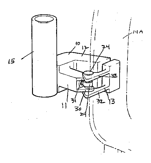
Figure 1 is a perspective view of a clamping device in
accordance with this invention;
Figure 2 is an exploded plan view of part of the
clamping device of Figure l;
Figure 2A is a plan view corresponding to Figure 2 but
showing the components assembled;
Figure 3 is an exploded end elevation view of part of
the clamping device in Figure l;
Figure 3A i6 an elevation view corresponding to Figure
3 but showing the components assembled;
Figure 4 iB an exploded end elevation view of the
clamping device in Figure 1;
Figure 4A is an elevation view corresponding to Figure
4 but showing the components assembled;
Figure 5 is a plan view of the clamping device in
accordance wlth Figure 1;
Figure 6 is an end elevation view of the clamping
device in accordance with Figure 1;
Figure 7 i6 a side elevation view of the clamping
device in accordance with Figure 1;
.,.,, .~, . . .

-- 3 --
Figure 8 is a side elevation view of a clamping device
in accordance with an alternative embodiment:
Figure 9 is an plan view of the device of Figure 8.
Figure 10 comprises perspective views illustrating
applications of a clamping device in accordance with this
invention;
Referring now to the drawings, Figure 1 illustrates a
clamping device comprising a main body 10 including a barrel
11 and a first clamping arm 12 extending laterally in one
direction from one end of the barrel. A second clamping arm
13 is pivotally mounted at the other end of barrel 11.
Clamping arms 12 and 13 cooperate to engage an article upon
which the clamping device is to be mounted, such as for
example, a section of an arm of a lawn chair illustrated at
14 in Figures 5 and 6 or 14A in Figure 1.
A holder 15 which may be in form of a tube with an
interior diameter of about one inch i8 mounted on barrel 11
to extend laterally in a direction opposite to the extension
of clamping arm 12. As shown in Figure 2, holder 15 is
mounted for pivotal movement about a horizontal axis
tran~veree to the central axis of barrel 11. Holder 15 has
a mounting portion 16 which i6 conical with the smaller
diameter close to holder 15. A retaining lip 17 is at the
~ar end of mounting 16 to prevent it from being fully
retracted from the main body 10. A serrated collar 28 is
al~o provided having teeth 19 to permit the holder to be
locked firmly in position at a variety of different angles.
Upon assembly of holder 15 with main body 10 as shown in
Figure 2A a compression spring 20 urges locking button 21
against conically shaped mounting 16 to urge teeth 19 into
engagement with teeth 22 in main body 10. This structure
provides a firm engagement between the holder 15 and the
main body 10 at a variety of positions. However, the
angular position of holder 15 can readily be adjusted by
pulling holder 15 out in a right hand direction with respect
to Figure 2A to disengage teeth 19 and 22 and permit pivotal
rotation.

- 4 -
A locking button 23 is also controlled by spring 20 and
it provides a cam follower for engagement with a cam 24
shown in Figure 5. Cam 24 is secured in position within
clamping arm 13 by pin 25 which engages locking button 26.
The interaction of cam 24 and cam follower 23 causes
clamping arm 13 to be biased into closed position to hold
the article of furniture such as 14 between the clamping
arms. Assembly is achieved in accordance with the
following:
1) Insert holder 15 into a hole 28 in body 10;
2) Insert locking button 21 into the bore 29 of
barrel 11;
3) Insert spring 20 into barrel 11 ensuring that it
seats over locking button 21;
4) Insert locking button 23 into bore 29 ensuring
that the button 23 seats into spring 20;
5) Position clamping arm 13 over projecting legs 30
and 31 in body 11 and slide pin 24 through the arms 32 and
3~ of clamp 13 and one leg 31 of body 11 and cam 24 ensuring
that the cam face is in alig Dent with locking button 23;
6) Position locking cap 26 through arm 32 of clamp
arm 13 and bottom leg 30 of body 11, pressing pin 25 and
locking cap 26 together until the pin locks into the locking
cap.
Figures 8 and 9 illustrate an alternative embodiment of
this invention in which there are two sections. The first
section 40 is as clamping section and the second section 41
is a holding section. The clamping section comprises a body
42 to which is pivotally secured jaws 43 and 44 which
preferably are faced with rubber or similar material as
shown at 45. Pivot pins 46 and 47 permit the jaws to pivot.
A wing nut 48 threadably engages jaws 43 and 44 to clamp the
device to an article of furniture. The first ~ection also
comprises serrated teeth 49.
The second section includes holder 41 which is mounted
; on body 50 having teeth 51 to engage teeth 49. A wing nut
52 i8 mounted on threaded shaft 53 50 as to clamp teeth 49
..... .

5 . ~ r h Q "
for a variety of positions of holder 41. In the embodiment
illustrated in Figures 8 and 9 the umbrella or other article
supported by the holder cannot pass through holder 41
because of the location of wing nut 52. This embodiment
5 will therefore be particularly suitable for supporting a
tray as illustrated in Figures lO(a) or lO(c) but can be
used with a small umbrella as shown in Figure lO(b). It will
however be appreciated that if desired holder 41 can be
located laterally of the wing nut to permit the shaft of the
umbrella to pass unimpeded down through the holder.
Figure 10 illustrates applications of this invention.
In Figure lO(a) what is known as a "resin" chair 60 has a
tray 61 attached to it by a clamp in accordance with this
invention. Figure lO(b) shows a chair 60 to which umbrella
62 has been secured by a clamp 63 in accordance with the
invention. Figure lO(c) shows that tray 64 can be secured
to chair 60 in a frontal position by clamp 65. Figure lO(d)
is a detail view of the top side of tray 64 showing a glass
holder recess 65. Figure lO(e) shows the underside of tray
64 including glass holder 65 and a stub 66 to be attached to
the holder of a clamp in accordance with the invention.
Figure lO~f) shows a pair of clamps 67 and 68 to be attached
to the side of a chair to support rods 69, which in turn
support awning 70.
It will be noted from Figure 10 that a clamping device
in accordance with this invention can readily be attached in
a variety of locations on the arms or elsewhere of outside
furniture of the type illustrated.

Representative Drawing
A single figure which represents the drawing illustrating the invention.
Administrative Status

2024-08-01:As part of the Next Generation Patents (NGP) transition, the Canadian Patents Database (CPD) now contains a more detailed Event History, which replicates the Event Log of our new back-office solution.

Please note that "Inactive:" events refers to events no longer in use in our new back-office solution.

For a clearer understanding of the status of the application/patent presented on this page, the site Disclaimer , as well as the definitions for Patent , Event History , Maintenance Fee  and Payment History  should be consulted.

Event History

Description Date
Inactive: IPC from MCD 2006-03-11
Time Limit for Reversal Expired 1997-08-14
Application Not Reinstated by Deadline 1997-08-14
Deemed Abandoned - Failure to Respond to Maintenance Fee Notice 1996-08-14
Application Published (Open to Public Inspection) 1993-02-04

Abandonment History

Abandonment Date Reason Reinstatement Date
1996-08-14
Owners on Record

Note: Records showing the ownership history in alphabetical order.

Current Owners on Record
RICHARD CHARLES MAYNE
LAURENCE GRAY
RICHARD WHYTE
Past Owners on Record
None
Past Owners that do not appear in the "Owners on Record" listing will appear in other documentation within the application.
Documents

To view selected files, please enter reCAPTCHA code :


To view images, click a link in the Document Description column (Temporarily unavailable). To download the documents, select one or more checkboxes in the first column and then click the "Download Selected in PDF format (Zip Archive)" or the "Download Selected as Single PDF" button.

List of published and non-published patent-specific documents on the CPD .

If you have any difficulty accessing content, you can call the Client Service Centre at 1-866-997-1936 or send them an e-mail at CIPO Client Service Centre.

({010=All Documents, 020=As Filed, 030=As Open to Public Inspection, 040=At Issuance, 050=Examination, 060=Incoming Correspondence, 070=Miscellaneous, 080=Outgoing Correspondence, 090=Payment})


Document
Description 
Date
(yyyy-mm-dd) 
Number of pages   Size of Image (KB) 
Abstract 1993-02-03 1 13
Drawings 1993-02-03 9 180
Claims 1993-02-03 2 64
Descriptions 1993-02-03 5 202
Representative drawing 1998-10-05 1 12
Fees 1995-05-30 1 39
Fees 1994-08-07 1 46
PCT Correspondence 1993-01-03 1 19