Note: Descriptions are shown in the official language in which they were submitted.
2076383
PROCESS AND ARRANGEMENT FOR CLEANING OF PIPE LINES.
The present invention relates to a process for cleaning
of pipe lines, especially ventilation pipes and ventilation
ducts of large cross-sectional area, in buildings, by means
of a cleaning means, which is connected via a supply conduit
to a source of pressure medium, for example a compressed air
compressor, and which cleaning means exhibi~s one or more
nozzle openings which are directed backwards towards the
supply conduit at an acute angle relative to a centre line
which extends through the fastening of the supply conduit in
the cleaning means. The present invention also relates to a
nozzle opening in the form of a mainly continuous annular
gap, which extends along the periphery of the cleaning means
and which is connected to the supply conduit and the source
of pressure medium, the medium being made to discharge
through the annular gap and partly clean inner walls of the
line, and partly, by way of forces of reaction from the
~is~h~rging medium, make the cleaning means move into the
pipe line.
The invention also relates to a cleaning arrangement for
carrying out the process, comprising a cleaning means in the
form of a rear piece, and a front piece detachably mounted on
the rear piece, for providing a nozzle opening in the form of
~- \
2016383
a mainly continuous annular gap which is directed backwards
towards the supply conduit at an acute angle towards a centre
line which extends through the fastening of a supply conduit
in the cleaning means, and the cleaning means is connected to
a source of pressure medium via the supply conduit.
Norwegian Patent No. 41,358 discloses a nozzle head for
cleaning pipes and passageways. The nozzle head which
comprises an annular continuous gap near the periphery of the
head, is connected to a hose supplying pressure fluid, and
the fluid is directed backwards through the gap to clean the
pipe and move the nozzle head further along the pipe.
However, the nozzle head of this prior art is intended and
designed also to rotate and to float about the middle of the
pipe in effecting the cleaning operation. Thus it is not
intenA~ to be in close contact with the pipe inner wall as
is the case with the present invention. Another example of
this kind of cleaning nozzle head is known from U.S. Patent
No. 1,587,194.
The object of the present invention is to provide a
process and an arrangement which produce a satisfactory
cleaning of pipe lines of loose dust, deposits and other
contaminants plus disinfection of the lines also. The
invention primarily aims to provide cleaning of ventilation
~r,
20763~3
pipes and ventilation ducts of large cross-sectional surface,
but being able to clean of contaminants all types of conduits
having dissimilar cross-sectional forms also lies within the
scope of the invention.
These objectives are achieved with the process of the
present invention which is characterised in that the cleaning
means is brought into contact with an inner wall of the line
in that a reduced pressure is established between the
cleaning means and the inner wall and that the cleaning means
is made to move around about the cross-section of the line by
twisting the supply conduit about its longitudinal axis. This
reduced pressure is preferably established by bringing the
annular gap on the cleA~ing means into close contact with
inner wall of the line and especially by adjusting the
cleaning means to assume an angle against inner wall of the
line.
The cleaning arrangement of the present invention is
characterised in that the cleaning means has largely the
shape of a ball wherein the continuous gap extends along the
outermost periphery of the cleaning means, said continuous
gap is established by the back piece exhibiting an external
conical surface extending along its periphery at its forward
end, while the front piece presenting a conical internal
surface corresponding to said back piece conical surface in
2a
~'`
~ '
207638~
order to, when used, establishing said annular gap and said
annular gap being directed back out towards the coupling
means at an angle of up to 30-60 degrees.
The before mentioned prior art patent apparatuses are
not able nor intended to operate in close contact with the
pipe inner wall like the cleaning means of the present
invention. The main feature for ob~i n i ng this close contact
effect with the present invention seems to be the different
new, and specific ball surface area design of the nozzle
head. One further important feature is that the length of
the gap defined by the conical back and front pieces
respectively of the present invention, seems to extend a
longer distance than the compared gaps of the prior art
nozzle heads, leading to a more concentrated fluid spray from
the gap in the nozzle head. These seem to be the main
conditions for establishing the reduced pressure between the
cleaning means and the pipe inner wall.
On cleaning a pipe line, a coupling arrangement is
arranged on an inspection opening, exhaust valve or the like,
which seals against the opening in the pipe line. A cleaning
means according to the invention which is arranged in the one
end of a flexible hose, is introduced through an insertion
opening in the coupling arrangement and into the pipe line.
2b
2016~3
The coupling arrangement is coupled by means of a conduit to
a vacuum cleaner arrangement or the like, which is utilised
to establish a reduced pressure in the pipe line. A pressure
medium, for example, compressed air or steam, is fed to the
cleaning means and which thereby causes the cleaning means to
move into the pipe line into contact with its inner wall and
convey with it the supply conduit for the pressure medium, so
that as a consequence of the high speed of discharge, the
outflowing medium loosens dust, deposits and other
contaminants on the inner wall of the pipe line. The dust or
the deposits are thereafter sucked out by means of the vacuum
cleaner arrangement.
X.`
WO91/1~99 PCT/NO91/~36
3 2076383
Surprisingly it has been found that the cleaning means can
be maintained in contact with each and all walls of the pipe
line, that is to say even largely vertical walls as well as
ceilings, as a consequence of the reduced pressure which is
formed between the wall and the cleaning means when the annular
gap of the cleaning means is brought into direct contact with a
wall of the line. This involves having to arrange the annular gap
at the outermost periphery of the cleaning means for it to be
able to be brought into such a contact with the wall in question.
The cleaning means must consequently have a shape which makes
this possible, such as for example a shape of a ball or two
double conical elements which are joined together at their bottom
portions or of another symmetrical form where the annular gap can
be arranged along an outer periphery.
It has been found practical to conduct the cleaning in
several steps, the first step consisting in making the cleaning
means move through the pipe line during feeding of a solvent. In
this step the primary objective is not to loosen dust and detach
deposits in the pipe line by means of the mechanical finishing
ability of the air, but to feed a cleaning agent which contri-
butes to the solubility of the deposits. The second step consists
in making the cleaning means move through the pipe line under
full pressure of the pressure medium, the speed of the cleaning
means being regulated by braking the introduction of thP supply
conduit in the pipe line. The dust and the deposits are conse-
quently released by means of the cutting action which is
produced by the medium which discharges from the annular gap on
the cleaning means, but also as a consequence of the irregular
movements of the cleaning means and impacts against inner walls
of the pipe line, and especially if the latter has a cross-
section with sharp corners, such as for example with a rectan-
gular or square cross-section. In spite of the occurrence of
possible sharp corners the cleaning means can be made to move
around in the cross-section as a result of the above described
twisting of the supply conduit. Preferably the supply conduit is
made to twist cyclically a number of rotations first in one
direction anZ thereafter in an equal number of turns in the
WO91~1~99 - PCT/N
_ 4
2076~83
Qpposite direction during the course of cleaning. When the
cleaning means is introduced to a desired position in the pipe
line the supply of pressure medium is cut off so that the
cleaning means can be drawn out of the pipe line without needing
to overcome the force of reaction from the medium which dis-
charges from the annular gap. Alternatively the medium can be
caused to discharge from the annular gap at a lower speed when
the cleaning means is to be drawn out of the pipe line.
On cleaning of ventila.ion pipes and ventilation ducts in
buildings pressure medium is preferably utilised in the form of
air which can be mixed with solvent or disinfectant in the
dissi~ilar cleaning steps. Even steam can be utilised as pressure i~
medium since the breadth of the annular gap in the cleaning means
can be reduced and produces a smaller discharge from the annular
gap compared with the case where compressed air is utilised. It
also lies within the scope of the invention to be able to combine
the utilisation of compressed air and steam since the solvent and
disinfectant can be fed to the pipeline by means of compressed
air while the actual cleaning is carried out by means of steam at
high pressure, for example at 180 kp/square cm.
Further features and advantages of the cleaning means
according to the invention are evident from an embodiment
described subsequently.
The invention will be described in the following text in the
form of an embodiment in combination with the accompanying
drawings, wherein:
Fig. 1 shows a cleaning arrangement according to the
invention in operation in a pipe-shaped duct illustrated in one
longitudinal section, and where a cleaning means in the arrange-
ment bears against an inner wall of the duct.
Fig. 2 shows a cleaning nozzle in the arrangement according
to Fig. 1 which is adapted for coupling of a hose.
Fig. 3 shows an alternative construction of the hose
coupling according to Fig. 2.
Fig. 4 shows a longitudinal section through the cleaning
nozzle according to Fig. 2, and partly dissassembled.
WO91/1~99 PCT/NO9l/0~ ~
2076383
Fig. 5 shows a side view of the cleaning nozzle according to
Fig. 4.
Fig. 6 shows a perspective view of the cleaning nozzle
according to Fig. 5.
FigS,7 and 8 show the utilisation of the cleaning arrange-
ment during cleaning of a ventilation duct.
Fig. 9 shows an alternative construction of the cleaning
nozzle which is arranged at a horizontal ceiling in a duct of
rectangular cross-section.
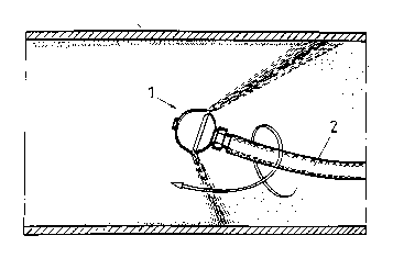
The cleaning arrangement which is illustrated in Fig. 1-6
comprises a cleaning nozzle 1, which is fixedly arranged in the
end of a flexible hose 2 for feeding compressed air ~o the
nozzle. The hose 2 is fastened on the cleaning nozzle 1 by means
of a hose clamp 3. The parts are shown disassembled in Fig. 2. In
Fig. 1 the cleaning arrangement is shown inserted in a pipe-
shaped duct where dust and deposits are to be removed from walls
of the duct. The cleaning nozzle 1 includes a rear piece 3 and a
front piece 4 dismantleable from this. The rear piece 3 is
provided with a coupling pipe 3.1 which the hose is secured to by
means of a hose clamp 5. The coupling pipe 3.1 can constitute an
integrated portion of the rear piece 3, such as is shown for
example in Fig. 2 and 4, or it can be secured with a suitable pin
3.2 such as is shown in Fig. 3. The rear piece 3 exhibits four
distribution holes 3.3 which are arranged sy~etrically about its
central axis, something which for one thing is evident from Fig.
6, and the holes 3.3 are connected to the coupling pipe 3.1 and
discharge into the forward end of the rear piece directed towards
the front piece 4. The front piece 4 which largely has the shape
of a hemisphere shows a mixing chamber 4.1 which extends
symmetrically about its central axis and which has the same
radius which the distribution holes 3.3 are arranged with around
the axis. The function of the mixing chamber 4.1 will be
described further below. The rear piece 3 furthermore presents an
external conical surface 3.4, which extends along its periphery
at its front end, and which corresponds to an internal conical
surface 4.2 on the front piece, the assembled cleaning nozzle 1
exhibiting an annular gap along the periphery of the nozzle which
W091/1~ ~ - PCT/NO91/0
- 207638:~
is directed back out towards the coupling piece 3.1. The-breadth
of the annular gap 6 can be regulated by means of a washer-7 the
thickness of which determines the breadth of the gap so that the
thicker washer 7 gives a broader annu ar gap 6. The front piece 4
is fixedly mounted on the rear piece 3 by~means of a screw 8
which passes through a central hole 4.3 in the front piece 4 and
is screwed into a threaded hole 3.5 in the rear piece 3.
During cleaning of a pipe-shaped ventilation duct, such-as
is shown in Fig. 1, an exhaust valve for example is replaced with
a coupling arrangement 20 as is illustrated in Fig. 7 and 8. The
coupling arrangement 20 presents a flange 21 sealed against a
wall and a bent pipe 22 projecting outwardly from the flange to
which there is coupled a suction hose which connects the bent
pipe to a vacuum cleaner arrangement or the like. The bent pipe
22 shows an insert opening 24 situated in the extension of the
centre line to the horizontal portion of the bent pipe 22 in Fig.
7 and 8, and through the opening is inserted the cleaning nozzle
1 with the hose 2. The cleaning operation consists in that the
cleaning nozzle 1 after the insertion in the ventilation duct
which is to be cleaned, is fed with compressed air which if
desired is fed with a cleaning agent and/or a disinfectant. At
high speed compressed air conse~uently discharges back out from
the annular gap along the periphery of the cleaning nozzle 1, so
that the nozzle is driven into the duct as a result of the forces
of reaction from the discharging air, and carries the hose 2 with
it. The cleaning nozzle 1 bears against inner wall of the duct
and is manoeuvred in a lateral direction in that the hose is
twisted to the one side or the other. Simultaneously the suction
hose 23 is placed under reduced pressure so that dust which is
released from inner walls of the duct is sucked away from the
duct and is collected in the vacuum cleaner arrangement which
moreover is not shown in the Figures. Dust and existing deposits
are released from inner walls of the duct partly as a result of
the cutting effect which is produced by the air discharging from
the annular gap 6, and partly as a result of irregular movements
of the cleaning nozzle 1 and impacts against inner walls of the
duct.
WO91/1~99 PCT/NO91/00036
- - 2076383
As a result of the reduced pressure which is formed at the
inner wall directly against the annular gap 6 the cleaning nozzle
1 is held firmly against inner walls of the duct and can be
manoeuvred forwardly to each and all inner surfaces in the duct
independently of the cross-sectional form of the duct, that is to
say both along largely vertical side surfaces in the duct and
surfaces which form ceilings of the duct.
An alternative construction of the cleaning nozzle 1 as
shown in Fig. 9 has substantially the same spherical shape as the
construction which is evident from Fig. 1-6, but shows beyond
this a conical portion 4.4 on the front piece 4 closest in to the
annul ar gap 6. The conical portion 4.4 shows a cone angle of a=15
degrees, but it can be between 10-40 degrees. If, as shown in the
example, the conical surfaces 3.4, 4.2, which lead forwards to
the annular gap 6 incline with a gap angle b=50 degrees the air
discharging from the annul ar gap 6 will be directed with an
impact angle c=35 degrees towards the ceiling surface which the
cleaning nozzle 1 bears against. The gap angle b can be 30-60
degrees. The impact angle c can vary within the region 5-40
degrees, prefera~ly 10-20 degrees, by selection of the cone angle
a and/or the gap angle b depending upon which type of duct the
cleaning nozzle 1 is intended to treat and depending on the type
of pressure medium and of possible cleaning agent which is to be
utilised. The conical portion 4.4 on the front piece 4 thus
stabilises the cleaning nozzle 1 into abutment with the surface
in question and prevents the cleaning nozzle 1 from swinging
forwards and backwards in its longidutinal direction something
which can reduce the result of the cleaning. It is also preferred
to employ a relatively soft hose 2 for feeding compressed air to
the cleaning nozzle 1.