Language selection

Search

Patent 2076411 Summary

Third-party information liability

Some of the information on this Web page has been provided by external sources. The Government of Canada is not responsible for the accuracy, reliability or currency of the information supplied by external sources. Users wishing to rely upon this information should consult directly with the source of the information. Content provided by external sources is not subject to official languages, privacy and accessibility requirements.

Claims and Abstract availability

Any discrepancies in the text and image of the Claims and Abstract are due to differing posting times. Text of the Claims and Abstract are posted:

  • At the time the application is open to public inspection;
  • At the time of issue of the patent (grant).
(12) Patent: (11) CA 2076411
(54) English Title: SHEET FEEDER
(54) French Title: DISPOSITIF D'ALIMENTATION EN FEUILLES
Status: Expired and beyond the Period of Reversal
Bibliographic Data
(51) International Patent Classification (IPC):
  • B65H 01/08 (2006.01)
  • B65H 01/26 (2006.01)
  • B65H 09/00 (2006.01)
(72) Inventors :
  • POLLICH, GERHARD (Germany)
  • CZOTSCHER, ERNST (Germany)
(73) Owners :
  • HEIDELBERGER DRUCKMASCHINEN AKTIENGESELLSCHAFT
(71) Applicants :
  • HEIDELBERGER DRUCKMASCHINEN AKTIENGESELLSCHAFT (Germany)
(74) Agent: DOUGLAS S. Q.C. JOHNSONJOHNSON, DOUGLAS S. Q.C.
(74) Associate agent:
(45) Issued: 1998-02-10
(22) Filed Date: 1992-08-19
(41) Open to Public Inspection: 1993-03-03
Examination requested: 1992-08-19
Availability of licence: N/A
Dedicated to the Public: N/A
(25) Language of filing: English

Patent Cooperation Treaty (PCT): No

(30) Application Priority Data:
Application No. Country/Territory Date
DE 41 29 132.8 (Germany) 1991-09-02

Abstracts

English Abstract


This invention concerns a sheet feeder which comprises a pile
table (2) being guided in laterally adjustable guides (5) so
as to be vertically movable, a non-stop device (6, 7)
likewise being guided in laterally adjustable guides (9) so
as to be vertically movable, and a device for automatic
alignment of at least one sheet side edge, said device having
a sensor detecting the position of a side edge and
controlling motor-driven adjustment elements (10, 11, 12) for
the lateral alignment movement of a pile-supporting carrier
before sheet transfer takes place; it also comprises means
through which the guides (5) for the pile table (2) and the
guides (9) for the non-stop device (6, 7) can be regulated
relative to one another in the direction of the lateral
alignment movement and can be jointly adjusted.


French Abstract

Dispositif d'alimentation feuille à feuille qui comprend une table d'empilage (2) dirigée vers des guides (5) réglables latéralement de façon à être déplacée verticalement, un dispositif continu (6, 7) dirigé lui aussi vers des guides réglables latéralement (9) de façon à être déplacé verticalement et un dispositif pour l'alignement automatique d'au moins un bord latéral de la feuille, ledit dispositif doté d'un capteur qui détecte la position d'un bord latéral et d'éléments de réglage actionnés par moteur (10,11,12) pour le mouvement d'alignement latéral d'un convoyeur d'empilage avant le transfert de la feuille; l'invention comprend aussi des dispositifs par lesquels les guides de la table d'empilage (2) et ceux (9) du dispositif continu (6, 7) peuvent être régularisés l'un par rapport à l'autre dans le sens du mouvement d'alignement latéral et peuvent être réglés en même temps.

Claims

Note: Claims are shown in the official language in which they were submitted.

- 7 -
C L A I M S
1. Sheet feeder comprising a pile table being guided in
laterally adjustable guides so as to be vertically
movable, a non-stop device likewise being guided in
laterally adjustable guides so as to be vertically
movable, and a device for automatic alignment of at least
one sheet side edge, said device having a sensor
detecting the position of a side edge and controlling
motor-driven adjustment elements for the lateral
alignment movements of a pile-supporting carrier before
sheet transfer takes place,
c h a r a c t e r i z e d
in that the guides (5) for the pile table (2) and the
guides (9) for the non-stop device (6, 7) are jointly
adjustable and can be regulated relative to one another
in the direction of the lateral alignment movement.
2. Sheet feeder according to Claim 1,
c h a r a c t e r i z e d
in that the guides (5) for the pile table (2) and the
guides (9) for the non-stop device (6, 7) are connected
with each other through an adjustment element (13, 14)
being operative in the direction of the lateral alignment
movement.
3. Sheet feeder according to Claims 1 and 2,
c h a r a c t e r i z e d
in that the adjustment element consists of a turnable
threaded spindle (13) and a threaded spindle nut (14)
being penetrated by said threaded spindle (13), said
threaded spindle nut (14) being fastened to the one
guide (5), whereas said threaded spindle (13) is mounted
on the other guide (9) so as to be axially not movable.

- 8 -
4. Sheet feeder according to Claims 1 to 3,
c h a r a c t e r i z e d
in that a further adjustment element (10, 11), being
operable in the direction of the lateral alignment
movement, adjustably connects the guide (9) for the
auxiliary pile device (6, 7) with a fixed side part (1)
of a frame and has a drive motor being controlled by the
sheet feed control, whereby the first adjustment
element (13, 14) adjustably connects said guide (9) in
the same manner with the guide (5) for the pile
table (2).
5. Sheet feeder according to Claims 1 to 4,
c h a r a c t e r i z e d
in that the motor-driven adjustment element (10, 11) for
the guide (9) opposite the side part (1) likewise
consists of a threaded spindle (10) which is axially
fixedly mounted in said side part (1) and penetrates a
threaded spindle nut (11) which is fastened to said
guide (9) for the non-stop device (6, 7).
6. Sheet feeder according to Claim 3,
c h a r a c t e r i z e d
in that the adjustment element (13, 14) being operative
between the guide (9) for the non-stop device (6, 7) and
the guide (5) for the pile table (2) can be turned
manually.

Description

Note: Descriptions are shown in the official language in which they were submitted.


2076~
She~t Fo~d~r
The ;nven~ion relat~s to a sheet feeder as st~ted in the
preamble of Clalm 1 of the present patent appl~cat~onO
Such ~ sheet feed~r for sheet-fed pr1ntin~ presses - howev~r,
~ithout a non-stop devlco - 1s known from the European
Patent Appl1cation A2 0 309 388.
Guides be~ng ~rranged so as to be later~lly adjustable ~or
the verticsl movement of a pile table usually being placed
above ~ pile board suspended by chains ~re operat~ve v~a
motor-driven~ sensor-~ontrolled ad~ustment elements, so that
th~ p1le t~ble can be l~terally al~gned in ~ccordanc~ w1~h
the amount of l~t~ral d~splacement of a shee~ sido edge
detected by tho sensor. The ~djustable element consists o~
rotatable, ~o~or-dr~ven spindle which is mounted ~t 9 p1le
board and penetrates an axially fixed threaded sp;ndle nut.
From the German Patent Application DE-OS 28 08 774 th~re ;s
also known 8 dev;ce for the later2l alS~n~ent o~ the ma;n
pile on a p1le table in a sheet feeder.
In the German Patent DE 29 11-735 there is described a device
for automatic alignment of at least one side edge of the
sheets in ~he auxiliary p;le of a non-stop device cons;sting
of a rod wh;ch is supported by a transverely extending rail
at the sheet front ed~e and at the sheet trailing edge,
respectively. This dev1ce, too, compr~ses a sensor which
detects the pos;tiQn of the sheet side edge and through which
the adjust~ent elements for laterally aligning the auxiliary
p;le are controlled. The ad justment elements also consist of
a spindle and a threaded sp1ndle nut ~hiçh, ir. this order,
are dr1ven by an electr;c motor. From this prior art there is
~ , .
: ,

2~6~
also known the arrange~ent of gu;des for the vertica~
movement of ~he ~ux~ ry p1le; however, these vert~cai
~uldes are fixedly dlsposed. There ls not mcnt~oned in this
~ p3t~nt that the m~n plle c~n have s~par~te means for
J automatls lateral ~l~gnment.
It ;s the object of the ;nventlon to provide a sheet feeder,
espesially for sheet-fed printin~ presses~ compr;sing the
gener~c character;stics as stated in the preamble of the
appended Claim 1 and be;ng designed such that a success~ve
feed of the main pile and the aux;l~ary p;le can
automatlcally take place throu~h ~ust one ad~ustment dev~ce
enabling a lateral Dd~ustment of the ma1n p1le w1th respect
to the auxiliary pile wh~le the press is in operat~on.
Ihs solut10n to this ob~ect is prov~ded by an embod~ment of
the inventlon h~v~ng the fe~tures as st~ted in the
characteri~1n~ part of the appended Gla1m 1.
W;th this embodiment ;t has been ach;eved that the automatic
alignment and successive feed of the main pile and the
auxiliary pile in a non-stop device takes place through a
single adjustment element, whereby an additional lateral
alignmene of the main pile with respect to the aux~liary p~le
is poss;bl~ wh;le the press is runningA Th~s has the
advantage ~hat the aux;liary p;le and s;multaneously a new
main pile fed into the ~eeder are automat;cally laterally
al;gne~ through the sheet feed controL. Subsequently, the ne~
main p;le can be ad3us~ed so as to ~lign its position to the
position of the auxiliary p;le, so that with the change-over
of the piles a trouble-free transition from the auxi liary
pile to the new main pile can take place.
~n a preferred embodiment of a feeder ~ith vertical guides
for the p;le table and vertical guides for the non-stop
device there is provided tha~ the guides for the non-stop
-2-
'
.
: ', ,~ ' , : ,

2076~ ~
device are connected to sta~ionary parts of the mach;ne frame
thrvugh an ad~ustmen~ element whlch ~s regulated by the sheet
feed control, and that D further ~d~ustmene element which 1s
actuated manuDlly or through a motor is prov~ded bet~een the
gulde ~or the non-stop dev~ce and the su1de for the ~er~ical
movement of the pile t~ble, ln order to be able to change the
lateral distance between both gu;des.
In another embodiment of the ~nvention thsre is arranged a
joint laterally adjustable guide which is connected with
sta~ion~ry part of the mach1ne frame throu~h an ~d~ustment
element belng regulated by the sheet feed control, and ~
further adjustment element is mounted d~rectly to the p1le
board , in order to adjust this pile board lateralLy with
respect to the joint gu;de.
Further essential features of the ~nvent~on are described in
Claims 3 an~ 4.
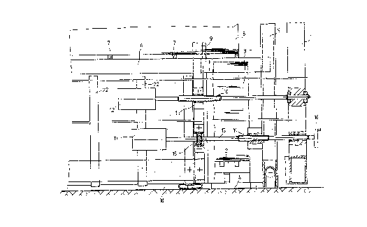
The pr~sent ~nvention will be best understood from the
follow;ng descript;on of specif;c embod;ments when read in
connection with the accompanying draw;ngs, in which:
Fig. 1 is a fragmentary front v~ew of an ad~ustment dev~ce
as seen in a d;rection couneer to the sheet
transport direction;
.
Fig. 2 ;s a view of a hor;zontal sect;on of the arrange~ent
according to Fig. 1, below an auxiliary p;le;
Fig. 3 is a partial front view of an altered embodiment of
~ an adjustment device, as seen in a direction counter
to the sheet transport direct;on; and
F1go 4 1s a view of a horizontal section of the arrangement
~ according to Fig. 3~ beLow the auxiliary pile~
--3--
" '
,
.:

- 2076~
ln the embod~ment as illus~rated ln Figs~ 1 and 2 a pile
table ~ for a ~a;n pi~e 3 is arranged on a p~le board 4
be~ween two s~de parts 1~ whereby ~he pile board 4~ for
ex~mple, is suspended by sha1ns which arc connected w~th a
dr~ve for performing ~he vert1cal move~ents of the pil~
board 4 and the pile table 2 be~ng arranged thereon. When
mov;ng vert;cally~ the pile board 4 i~ gu1ded ln ~ guide 5
~hich ~s arran~ed so as to be laterally movable, in order to
enable the lateral al;gnment movemen~s ~f the maln pile 3.
The front-s1de non-stop ra~l 6 and the back-s~de non-stop
rail not illustrated in the drawin~s are arr~n~ed ~t ~ chain
hoisting gear also not illustrated in eh~ dra~;ngs and serve
as a support for the non-stop rods 7 which are ~nserted from
the rear ln sheet transport directi~n ~n support of the
au~1liary pile 8 for the non~stop ope~at~on. The non-stop
ra~ls 6, on both s~des~ are guided ~n vertic~l guides 9 ~hich
~re arranged so as to also be lateral~y mov~ble. A threaded
spindle 10 penetratss a threaded spindle nut 1~ fastened to
the guide 9, and ;ts one end ;s ax~ally fixed while being
turnably mounted in a side wall 1 of the mach;ne frame. The i~
other end of the threaded sp;ndLe 10 ~s connected ~ith a gear
motor 12 ~hich is re~ulated by the sheet feed control. A
further threaded spindle 13 penetrates a threaded spindle
nut 14 fastened to the vert;cal guides ~ for the pile
table 2, and it is rotatably mounted in a radial/axial
bearing 15 being arranged at the gu1de 9 but 1s not slidable
in ax;al d;rec~ion. Thus~ this threaded sp1ndle t3 connects
the verti~al guide 5 for the pile table 2 w;th the vertical
guide 9 for the front-s;de non-stop rail 6~ so that the
gu;des 9 and 5 are jointly laterally adjusted through the
gear ~otor 12 which is regulated by the sheet feed control.
The bask-s;de non-stop rail (aux;l;ary p;le rail) is ~ounted
so as to easily be laterally slidable and is moved along w~th
the non-stop rods 7 and the pile resting thereon~ It ;s also
-4-
,
,
~ : ~ . ~ : , ': .
' ~ ,
'. : ' ' . .:

~3~ A-~47 07. ~
poss~ble th~t a rig~d conn~ct~on ;s pro~ided between the twg
non-stop rails~ Vîa the th~e~ed spindl~ 13 whi~h 1s turna~Le
through ~ handwheeL 16 ~nd alternative~y ~r addi~onaLly
through ~ motor 17 an adjustment of the ~ert;cal ~u1d~ 5 ~or
the p~le table 2 with respcct to the verti~L ~uide 9 fo~ the
n~n-stop raiL 6 c~n take pl~ce~ ~ that ~he m~1n p~o 3 can
be al1yned on onc hand vS~ the ~heet feed c~ntrol hnd ~n ~he
bther hand sdd;~nally by hand through the operati~n of the
~and wheel 1h or ~he ge~r motor 17~
Fig. 2 ;~lustrates an embod1ment, where1n the gu~de 9 be~ng
composed of several ind1vidual eLements can be operated ~n
vertical direction as a guide for the pile board 4 as well as
for the non-stop device not shown in F;g. 2. A transversely
extending guide bar 18 ;s connected w;th the gu;de 9 through
a guide pin 19 so as to be vert;cally movable. A sl;ding
part 21 be1ng fasSened to the pile board 4 can be moved
horizontally ;n a slot-shaped notch 20 of the ~1de bar 18
and Locked in ~ gradation formed in said g~ide b~r 18, so
that a fixed connection in sheet transport dlrect;on is
established be~ween the ~uide 9 and the p~le board ~.
However, thls ~onnect;on ;s horizontally movable through the
sL;ding part 21 in the notch Z0 and also vertically movable
thr~ugh the gulde p~n 19~ The p~per stops extending
vertlcally 1n parallal to one another ~re 1dentlf1ed ;n the
drawings by the numeraL 22
h s;mplified version ~ the inVÇntl~Je ld~a 1~ us~ ~-t~d ~r~
F~gs~ ~ an~ 4. Only ~ne vqrt;~al gu~de ~ i~ pro~J~ded 1n this
e~bodlment, ~on~ whi~h the non~sto~ ra; Ls ~ c~rry~n~ the
a~xi~iary p;le 8 v~a the n~n-stop rods 7 a~ welL ~s the p~le
board ~ carryin~ the m~i~ pile 3 o~ th~ p~le t~le 2 ~re
~uided. A threaded spindle 1~ c~nnects the g~ide ~ w1th the
site part t of ~he ~a~hine f~ame (not i ~ustrated~ The
thr~ded sp1nd~e 10 penetrat~S a ~hrea~d ~p~r~d~Q nut 11
~aste~ed to ~he guide 9 an~ can be d~ven th~ough a gear
_5_
~,
-
O~
,

207~
.HEIDELBERC~ A-847 a7.05.1992
f imw.e
motor which ;s re~ulated by the sheet feed control. A further
threaded spindle 13 whlch is axially not movabLe is turnably
~ounted directly on the p1le board 4 and penetrates a
threaded spindle nu~ 14 whlch ~s f;xedly connected to the
guide bar 18, ~nd a f1xed connect10n of ~a1d guide ~3r 18 to
parts of guide 9, in shee~ tr~nsport d~rrction, 1s brou~ht
about through a guide.p~n 19, just as descr~bed with respect
to Fig. 2. With this arrangement a lateral al1gnment movement
of the auxiliary pile be;ng supported by the non-stop rails
as well as of the main pi(e being supported by the p;le
table 2 on the p;le board 4 takes place v1a the threaded
spindle 1û, and the main pile can additionally be laterally
aligned with respect to the auxil1~ry p~le by turn1ng the
threaded spindle 13. Instead of mounting the threaded
spindle 13 on the p;le board $~ as illustrated in Figs. 3 and
4, it also c~n be mounted d~rectly on parts of guide Y, so
that the threaded spindle nut 14 being penetra~ed by ~he
threaded spindle 13 is to be fastened on the pile board 4.
~ith this simpl;f;ed construction there ~s provided a hand
~heel 16 in place of ~ motor for oper~ting the threaded
spindle 13.
.
... . .
~ ' ' ' ' ,: ' ': - '
. .
,

Representative Drawing
A single figure which represents the drawing illustrating the invention.
Administrative Status

2024-08-01:As part of the Next Generation Patents (NGP) transition, the Canadian Patents Database (CPD) now contains a more detailed Event History, which replicates the Event Log of our new back-office solution.

Please note that "Inactive:" events refers to events no longer in use in our new back-office solution.

For a clearer understanding of the status of the application/patent presented on this page, the site Disclaimer , as well as the definitions for Patent , Event History , Maintenance Fee  and Payment History  should be consulted.

Event History

Description Date
Inactive: IPC from MCD 2006-03-11
Time Limit for Reversal Expired 2001-08-20
Letter Sent 2000-08-21
Grant by Issuance 1998-02-10
Inactive: Final fee received 1997-10-31
Pre-grant 1997-10-31
Notice of Allowance is Issued 1997-09-23
Letter Sent 1997-09-23
Inactive: Status info is complete as of Log entry date 1997-09-16
Inactive: Application prosecuted on TS as of Log entry date 1997-09-16
Inactive: IPC removed 1997-08-11
Inactive: First IPC assigned 1997-08-11
Inactive: IPC assigned 1997-08-11
Inactive: Approved for allowance (AFA) 1997-08-08
Application Published (Open to Public Inspection) 1993-03-03
Request for Examination Requirements Determined Compliant 1992-08-19
All Requirements for Examination Determined Compliant 1992-08-19

Abandonment History

There is no abandonment history.

Maintenance Fee

The last payment was received on 1997-07-28

Note : If the full payment has not been received on or before the date indicated, a further fee may be required which may be one of the following

  • the reinstatement fee;
  • the late payment fee; or
  • additional fee to reverse deemed expiry.

Patent fees are adjusted on the 1st of January every year. The amounts above are the current amounts if received by December 31 of the current year.
Please refer to the CIPO Patent Fees web page to see all current fee amounts.

Fee History

Fee Type Anniversary Year Due Date Paid Date
MF (application, 5th anniv.) - standard 05 1997-08-19 1997-07-28
Final fee - standard 1997-10-31
MF (patent, 6th anniv.) - standard 1998-08-19 1998-07-23
MF (patent, 7th anniv.) - standard 1999-08-19 1999-07-19
Owners on Record

Note: Records showing the ownership history in alphabetical order.

Current Owners on Record
HEIDELBERGER DRUCKMASCHINEN AKTIENGESELLSCHAFT
Past Owners on Record
ERNST CZOTSCHER
GERHARD POLLICH
Past Owners that do not appear in the "Owners on Record" listing will appear in other documentation within the application.
Documents

To view selected files, please enter reCAPTCHA code :


To view images, click a link in the Document Description column (Temporarily unavailable). To download the documents, select one or more checkboxes in the first column and then click the "Download Selected in PDF format (Zip Archive)" or the "Download Selected as Single PDF" button.

List of published and non-published patent-specific documents on the CPD .

If you have any difficulty accessing content, you can call the Client Service Centre at 1-866-997-1936 or send them an e-mail at CIPO Client Service Centre.

({010=All Documents, 020=As Filed, 030=As Open to Public Inspection, 040=At Issuance, 050=Examination, 060=Incoming Correspondence, 070=Miscellaneous, 080=Outgoing Correspondence, 090=Payment})


Document
Description 
Date
(yyyy-mm-dd) 
Number of pages   Size of Image (KB) 
Drawings 1994-03-11 4 118
Description 1994-03-11 6 221
Claims 1997-06-10 2 67
Abstract 1994-03-11 1 24
Claims 1994-03-11 2 61
Description 1997-06-10 7 332
Abstract 1997-06-10 1 13
Representative drawing 1998-02-15 1 21
Commissioner's Notice - Application Found Allowable 1997-09-22 1 164
Maintenance Fee Notice 2000-09-17 1 178
Correspondence 1997-10-30 1 38
Fees 1996-07-25 1 50
Fees 1994-07-24 1 60
Fees 1995-07-25 1 48
Courtesy - Office Letter 1993-04-15 1 67
Examiner Requisition 1995-09-18 2 59
Prosecution correspondence 1996-03-10 2 46
Prosecution correspondence 1993-10-04 2 36