Language selection

Search

Patent 2076438 Summary

Third-party information liability

Some of the information on this Web page has been provided by external sources. The Government of Canada is not responsible for the accuracy, reliability or currency of the information supplied by external sources. Users wishing to rely upon this information should consult directly with the source of the information. Content provided by external sources is not subject to official languages, privacy and accessibility requirements.

Claims and Abstract availability

Any discrepancies in the text and image of the Claims and Abstract are due to differing posting times. Text of the Claims and Abstract are posted:

  • At the time the application is open to public inspection;
  • At the time of issue of the patent (grant).
(12) Patent: (11) CA 2076438
(54) English Title: PROGRAMMABLE URINAL FLUSHING DELAY CIRCUIT
(54) French Title: CIRCUIT DE DELAI PROGRAMMABLE DE CHASSE D'EAU
Status: Expired
Bibliographic Data
(51) International Patent Classification (IPC):
  • G05D 7/00 (2006.01)
  • E03D 13/00 (2006.01)
  • G01P 13/00 (2006.01)
(72) Inventors :
  • ALLEN, CHARLES S. (United States of America)
  • VUONG, NHON T. (United States of America)
(73) Owners :
  • SLOAN VALVE COMPANY (United States of America)
(71) Applicants :
(74) Agent: DENNISON ASSOCIATES
(74) Associate agent:
(45) Issued: 1998-07-28
(22) Filed Date: 1992-08-19
(41) Open to Public Inspection: 1993-03-07
Examination requested: 1994-07-14
Availability of licence: N/A
(25) Language of filing: English

Patent Cooperation Treaty (PCT): No

(30) Application Priority Data:
Application No. Country/Territory Date
07/756,298 United States of America 1991-09-06

Abstracts

English Abstract


An apparatus for controlling flushing of a toilet
device detects use of the toilet device and compares the actual
number of uses against a preset number of uses which are
permitted before flushing of the toilet device. When the actual
number of uses equals the predetermined number of uses, the
toilet device is flushed. At the first use of the toilet device
after flushing, a timing cycle is initiated and the timing cycle
will cause flushing of the toilet device unless there is the
predetermined number of uses of the device within the period of
the timing cycle.


French Abstract

Dispositif permettant de réguler la chasse d'eau d'une cuvette sanitaire. Le dispositif détecte toute utilisation de la cuvette sanitaire et compare le nombre réel d'utilisations par rapport au nombre préétabli d'utilisations permises, qui détermine le déclenchement de la chasse d'eau. Lorsque le nombre réel d'utilisations correspond au nombre préétabli, la chasse d'eau est déclenchée. Dès la première utilisation de la cuvette sanitaire après une chasse d'eau, un cycle de minuterie est activé et, s'il s'écoule avant que le nombre déterminé d'utilisations ne soit atteint, il déclenche la chasse d'eau.

Claims

Note: Claims are shown in the official language in which they were submitted.


-1-

THE EMBODIMENTS OF THE INVENTION IN WHICH AN EXCLUSIVE
PROPERTY OR PRIVILEGE IS CLAIMED ARE DEFINED AS FOLLOWS:

1. A circuit for controlling electric operator
flushing of a toilet device including means for detecting
use of a toilet device and providing a signal
representative thereof, a counter connected to said
detecting means for receiving said signals and for
accumulating a count thereof representative of a number of
detected uses of the toilet device, a comparator connected
to said counter to receive a signal therefrom
representative of the accumulated count of the number of
detected uses of the toilet device, said comparator having
a preset number stored therein representative of the number
of uses of the toilet device before flushing thereof, said
comparator providing an output signal when the detected
number of uses of the toilet device is less than the preset
number, timing means connected to said comparator to
receive the comparator output signal therefrom, which
timing means initiates a timing cycle in response to said
comparator output signal, an electric operator driving
circuit means for use in flushing a toilet device and
connected to said timing means, said timing means providing
an operating output signal to said driving circuit means at
the end of the timing cycle, said counter having the same
preset number stored therein as said comparator, said
counter including means therein for comparing the
accumulated count of the number of detected uses and said
preset number and for providing a counter output signal
therefrom when the accumulated count equals said preset
number ,said counter being connected to said driving
circuit means to provide said counter output signal thereto
for operating said driving circuit.

2. The circuit of Claim 1 further characterized by and
including an OR gate having one input connected to the
output of said counter and a second input connected to the
output of said timing means, said OR gate having an output

-2-

connected to said driving circuit whereby a signal from
either said counter or said timing means to said OR gate
actuates the driving circuit.

3. The circuit of Claim 1, further characterized in
that the output of said counter is connected to a reset
input of said timing means and the output of said timing
means is connected to a rest input of said counter.

Description

Note: Descriptions are shown in the official language in which they were submitted.


2 ~
PROGE~ lhBLE URINAL FLUSHING DELAY CIRCUIT


l~IE FIELD OF THE lN~/ ~'N'l'LON
The present invention relates to automatic control
circuits for flushing toilet devices such as urinals commonly
found in public washroo~s. Because of the substantial need to
conserve water, it is believed that toilet devices, particularly
urinals, need not be flushed after every use, although they
should be flushed within a predetPr~ine~ time period after use.
Sloan Valve Company of Fr~nklin Park, Illinois, the assignee of
the present application, salls an au~omatic flu~hing circuit
under the tr~ rk "OPTIMA" which detects the use of a urinal
and then causes automatic flushing thereof after the user leaves
the area of the urinal. ~he present inYention utilizes that
detection circuit to register the , h~r of uses of ths urinal,
and when that number is equal to the permitted number o~ uses
before flushing, the circuit will initiate a flushing cycle. At
the first use of the urinal after it has been flushed, a tLming
cycle is initiated which ~ilL effect flushing of ~he urinal if
there has not been the predet~rrine~ number of uses thereof
during the timing cycle.
S~MNARY OF THE INVENTION
The presPnt invention relates to automatic controL
circuits for flushing toilet devices such as urinals and in
particular to such a contrsl circuit which will initiate flushing
~ 1

? 2 ~ 7 6 ~ ~ ~

of the toilet devic~ either after a predetermined number of uses
thereof or ~ithin a predet~m;ned ~ime period ~fter the initi~l
use.
A primary purpose of the invention is a con~rol circuit
S as described which is simple in construction and reliably
operable.
Another purpose is a control circuit for the automatic
flushing of toilet devices such as urinals which will effec~ a
~lushing of the urinal after a predete ined number of uses
thereof.
Another purpose of the invention is a contxol circuit
as described which will cause a flushing of the toilet device a
predet~ i n~ time period after the first use thereof.
Other purposes will appear in the ensuing
specification, drawing and claims.
. BRIEF DESCRIPTION OF THE DRAWING
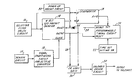
; The invention is illustrated diagrammatically in the
: attached schematic diagram of the control circuit described
herein.
DESC~IPTION OF THE PREFERRED EMBODIMENT
U.S. Patent 4,309,781 owned by Sloan Valve Company of
; Fr~nklin Park, Illinois,:the assigne0 of the present application,
: ~ describes a sensor circuit for detec~ing use of a urinal and
~ causing automatic flushing thereof af~er the user has left the
:
- 25 area. A commercial product utilizing this technology is sold by
Sloan Valve ~o~pany under the tr~ rk ~'OPTIMA~. The present


'
':
'~
~: ~
- ' : ' .'' ,

g

invention uses the detection circuit of the '781 patent as a
means for detecting use of the urinal. The number of uses are
counted and when that number equals a preset number,
representative of the permitted number of uses of the urinal
before required flushing, then the electric operator for flushing
the urinal is activated. The first use of the urinal after
flushing also starts a timing cycle. If there has not been the
predet~ ined number of uses of the urinal within the period of
the timing cycle, the urinal will be ~1ushed.
In the drawing, the sensor circuit as described in the
~781 patent is indicated at 10 and is connected to a signal
conditioning circuit and an AC to DC co~erter 12. The converter
12 will provide an output pulse to the clock input of a counter
14 for every detected use of a toilet device.
Circuit 16 is representative of a means for se~ting the
desired number of uses of a toilet device before it is to be
flushed. This may include manll~l switches or other means in
; which a preset number can be determined and that number is
provided to one input of counter 14. The number representing
permitted uses of the urinal before flushing is also provided to
; a somparator circuit 18 at the input designated A. Comparator 18
also receives a B input which is representative of the actual
nnmh~r of uses of the toilet device as det~r~;ned from the
advancing clock input to counter 14. Counter 14 stores both the
preset number of uses and the actual number of uses as indicated
by the advancing clock input.

. .


~ ~ ,
;

~07~

Comparator 18 is connected to a programmable ti~ing
circuit 20 which may receive an input ~rom a tLme set circuit 22.
The time set input is indicative of a time period within which
the toilet device must be flushed after initial use. Timing
circuit 20 has an output on line 24 which is connected to an O~
logic gate 26. Output 24 from the timing circuit is also
connected, through an isolation diode 25, to the reset input of
counter 14. Similarly, counter 14 has an output on line 28 which
is connected to another input of OR logic gate 26 with the
counter output also being connected to the reset input of timing
circuit 20. OR gate 26 is connected to a solenoid driver circuit
30 which will provide an output signal to operate the electric
operator to cause flushing of the toilet device, and in the
"OPTIMA" system, this is a solenoid. A power-up preset circuit
32 may be used to prevent an undesired flushing operation when
the circuit is initially tuxned on.
- In use, the sensor circuit 10 will provide an output
signal to converter 12 whenever the toilet device has been used.
Each such ; n~; c~tion of use provides an input to the clock
t~rm; n~ 1 of counter 14. Nhen the advancing number of uses from
the clock signals equals the preset number stored in circuit 14,
there is an output from counter 14 on line 28 to OR gate 26.
Such an input to the OR gate will cause the solenoid driver 30
to operate the solenoid to flush the urinal.
Comparator 18 has the same preset number as counter 14
and receives an input at t~r~i n~ 1 B indicative of the number at
,~


3 g
the clock input o~ the counter. At the first clock signal to the
counter, there is a comparison made at comparatsr 18 and if the
two input numbers thereto are unequal, there will be a signal to
the timing circuit 20 to initiate a timing cycle. Once the
timing cycle has started, the timing circuit is not responsive to
any further outputs from comparator 18. The timing circuit is,
however, reset upon an output si~nal from counter 14 indicative
of a signal to cause a flushing of the toilet de~ice. However,
if there is no such input to the reset te i n~ 1 of timing circuit
20 within the time period set by ~ me set circuit 22, the t,;m; n~
circuit will provide a~ output to OR gate 26 which will cause a
flushing of the toilet device.
An output ~rom either the timing circuit or the
cou~ter, both of which will effect ~lushing of the toilet device,
has the additional effect of resetting both of these circui~s to
start a new cycle of operation.
Whereas the preferred form o~ the in~ention has been
shown and described herein, it should be realized that there may
be man~ modifications, substitutlons and alte~ations thereto.

'

Representative Drawing
A single figure which represents the drawing illustrating the invention.
Administrative Status

For a clearer understanding of the status of the application/patent presented on this page, the site Disclaimer , as well as the definitions for Patent , Administrative Status , Maintenance Fee  and Payment History  should be consulted.

Administrative Status

Title Date
Forecasted Issue Date 1998-07-28
(22) Filed 1992-08-19
(41) Open to Public Inspection 1993-03-07
Examination Requested 1994-07-14
(45) Issued 1998-07-28
Expired 2012-08-20

Abandonment History

There is no abandonment history.

Payment History

Fee Type Anniversary Year Due Date Amount Paid Paid Date
Application Fee $0.00 1992-08-19
Registration of a document - section 124 $0.00 1993-03-23
Maintenance Fee - Application - New Act 2 1994-08-19 $100.00 1994-07-14
Maintenance Fee - Application - New Act 3 1995-08-21 $100.00 1995-07-10
Maintenance Fee - Application - New Act 4 1996-08-19 $100.00 1996-07-26
Maintenance Fee - Application - New Act 5 1997-08-19 $150.00 1997-07-28
Final Fee $300.00 1998-03-26
Maintenance Fee - Patent - New Act 6 1998-08-19 $150.00 1998-07-24
Maintenance Fee - Patent - New Act 7 1999-08-19 $150.00 1999-07-29
Maintenance Fee - Patent - New Act 8 2000-08-21 $150.00 2000-08-11
Maintenance Fee - Patent - New Act 9 2001-08-20 $150.00 2001-07-30
Maintenance Fee - Patent - New Act 10 2002-08-19 $200.00 2002-07-17
Maintenance Fee - Patent - New Act 11 2003-08-19 $200.00 2003-07-14
Maintenance Fee - Patent - New Act 12 2004-08-19 $250.00 2004-07-19
Maintenance Fee - Patent - New Act 13 2005-08-19 $250.00 2005-07-06
Maintenance Fee - Patent - New Act 14 2006-08-21 $250.00 2006-08-14
Maintenance Fee - Patent - New Act 15 2007-08-20 $450.00 2007-08-14
Maintenance Fee - Patent - New Act 16 2008-08-19 $450.00 2008-08-14
Maintenance Fee - Patent - New Act 17 2009-08-19 $450.00 2009-08-06
Maintenance Fee - Patent - New Act 18 2010-08-19 $450.00 2010-08-05
Maintenance Fee - Patent - New Act 19 2011-08-19 $450.00 2011-08-04
Owners on Record

Note: Records showing the ownership history in alphabetical order.

Current Owners on Record
SLOAN VALVE COMPANY
Past Owners on Record
ALLEN, CHARLES S.
VUONG, NHON T.
Past Owners that do not appear in the "Owners on Record" listing will appear in other documentation within the application.
Documents

To view selected files, please enter reCAPTCHA code :


To view images, click a link in the Document Description column. To download the documents, select one or more checkboxes in the first column and then click the "Download Selected in PDF format (Zip Archive)" or the "Download Selected as Single PDF" button.

List of published and non-published patent-specific documents on the CPD .

If you have any difficulty accessing content, you can call the Client Service Centre at 1-866-997-1936 or send them an e-mail at CIPO Client Service Centre.


Document
Description 
Date
(yyyy-mm-dd) 
Number of pages   Size of Image (KB) 
Claims 1997-06-25 2 61
Description 1994-03-27 5 195
Drawings 1994-03-27 1 40
Cover Page 1994-03-27 1 20
Abstract 1994-03-27 1 17
Claims 1994-03-27 3 101
Claims 1998-05-21 2 61
Cover Page 1998-07-15 1 49
Representative Drawing 1998-07-15 1 14
Correspondence 1998-03-26 1 38
Prosecution Correspondence 1994-07-14 1 49
Prosecution Correspondence 1997-06-10 1 33
Examiner Requisition 1997-02-07 2 91
Prosecution Correspondence 1994-09-29 2 81
Office Letter 1994-08-26 1 44
Fees 1996-07-26 1 43
Fees 1995-07-10 1 42
Fees 1994-07-14 1 44