Note: Descriptions are shown in the official language in which they were submitted.
- SLACKLESS DRAWBAR SYSTEM 2 ~ 7 ~ 5 7 2
FIELD OF THE I~v~N~l~lON
This invention relates to drawbar coupling systems and in
particular to a slackless dxawbar system having 2 fixed pivot pin.
The invention is described and illustrated in connection with a
railway application where it may be commonly used to connect cars
in a dedic2ted service such as coal or ore opera-ion or container
service. In these applications it is not necessary to provide
standard Association of American Railroads (AAR) couplers and/or
draft gear since the cars are only rarely uncoupled but it is
desirable to avoid impacts due to the take-up o slack wh~ch can
cause damage to equipment and/or lading.
A co-pending application relating to this application has
matured in.o Canadian Patent No. 1,337,720, grznted December 12,
1995 with the title of "SLACKLESS DRAWBAR" anc assigned to the
assignee o ~the present invention.
BACKGROUND OF THE INVENTION
The avoidance of shock loads caused by the take-up of slack
between cooperating elements of the system through which draft and
buff loads are applied to a train during in-track operation, has
long been 2 concern of railway operators. In some dedicated train
operations it is advantageous to avoid the weight and cost of
standard ~R couplers and draft gear by replacing them
~ 7~2 J
with light-weight, simple drawbars but this means that slack take-
up and impact dissipation systems included in the el; m; n~ted
equipment are also eliminated. Therefore it has been a goal in
designing drawbar systems to eliminate slack. It is also desirable
to keep the apparatus light in weight, strong enough to withstand
m~X;mum draft and buff loads and flexible enough to handle side to
side and fore and aft angling as required by AAR rules to meet
operating conditions.
Slackless systems have been provided before, for example U.S.
patent number 4,580,686 illustrates a wedge-shaped slack take-up
member and U.S. patent nu~h~r 4,966,291 shows - ~otary drawbar.
SUMMARY OF THE INVENTION
This invention provides improvements over U.S. patents
4,580,686 and 4,966,291. Th~ invention comprises a support member
or casting adapted to be directly secured to the center sill of a
railway car and which in turn supports all the other parts of a
drawbar system. This casting also protects the center sill from
excessive wear caused by the drawbar system. The invention further
comprises a pivot pin through which draft load is transmitted from
a drawbar to the support member, a pair of bushings fixed in t~
support casting for spreading the load from the drawbar over a
relatively broad area of the support casting, a follower for
transferring buff loads to the butt end of the drawbar and a siack
adjusting wedge for taking up slack between operative parts of the
.~
j -- 207~7~
-
system and maint~;n;ng the follower in close contact with the butt
end of the drawbar. Suitable attaching and retA; n; ng parts are
also provided. Components of the drawbar system of the invention
are made of appropriate material to withstand the typé of loading
or stress to which each will be subjected and are hardened and/or
otherwise treated as necessary to achieve the best results.
The system is designed to el;m;nAte or reduce stress
concentrations. This is accomplished in part by providing smooth
transition curves between intersecting surfaces of load carrying
members, enlarging the radii of load carrying curved surfaces,
utilizing wear resistant steel and hardening surfaces subjected to
wear. Hardened bushings are interposed between the pivot pin and
the pinhole in the support casting to apply draft loads over a
relatively broad surface area rather than at a high-stress contact
line .
The invention is simply constructed with a m;n;mllm number
of parts and can be easily assembled, disassembled and maintained
without special or expensive tools. It has low wear
characteristics which result in a relatively long life and can
compensate for initial slack and appreciable additional wear in the
draft components. When such wear reaches the r~ lm which can be
compensated for, the wear-compensating member can be easily
replaced by a thicker member for additional life of the~system.
Visual wear indications are provided which are readily observable
from either the top or the bottom of the assembly showing when the
system has reached its useful limit of compensation for slack. The
wear-compensating member can be removed from the bottom of the
assembly by removing bolts holding a support plate.
While it is recognized that a slackless draft system incurs
reduced load levels in both draft and buff conditions, the
invention is capable of handling the same ultimate loads as a
conventional system, i.e., at least about 900,000 pounds in draft
and at least about 1,200,000 pounds in buff. This permits use of
the invention in trains which include conventionally coupled
cars.
Further the invention is designed so that it can readily be
applied to a conventional railway car having a center sill with a
minimum amount of modification of the center sill being required
and eliminates the need for installation of draft stops.
This invention provides a drawbar system which avoids shocks
and excess loads caused by slack, yet is lighter in weight and is
capable of handling the same ~ m draft and buff loads as
previously know apparatus.
The drawbar system of this invention when used with the
drawbar described in the above-said Canadian Patent No. 1,337,720
is significantly lighter than a standard AAR coupler and draft
gear permitting a reduction in energy costs and/or a greater
payload.
OBJECTS OF THE lNV~:N~l~ION
It is an object of this invention to provide a slackless
drawbar system that can readily be applied to a standard railway
car without requiring any modification of the car.
~ ~.A
, .. . .
- - 207~572
Another object of this invention is to provide a
slackless drawbar system which offers a substantial savings in
weight over conventional coupler and draft gear systems.
It is also an object of this invention to provide
slackless drawbar system which avoids slack in both draft and buff
modes.
Still another object is to provide such a system
specifically designed to avoid high stress concentration and high
wear areas for reliability and long life.
These and other objects and advantages will become
apparent from the attached drawings and written description.
BRIEF DESCRIPTION OF T~E DRAWINGS
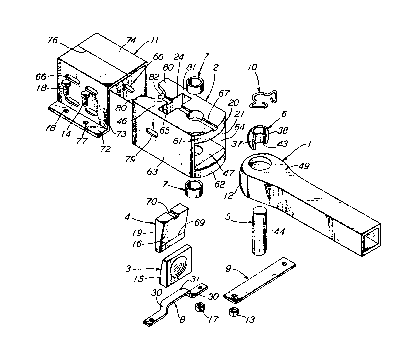
Figure 1 is an exploded view of the elements of a
slackless drawbar system utilizing the support member or casting of
the invention.
Figure 2 is a cross-sectional view taken along line II-II
in Figure 3 of the support member of this invention shown connected
between a drawbar and a railway car center sill.
Figure 3 is a cross-sectional view of the drawbar system
of this invention taken along line III-III in Figure 2.
DESCRIPTION OF T~E PREFERRED EMBODIMENT
As can be seen in Figure 1, the slackless drawbar system
of the invention comprises a drawbar 1 which fits into a support
member or casting 2 in contact with a follower 3 which -is held in
close contact with the butt or inner end 12 of the drawbar by a
slack take-up wedge 4. Draft force is applied from drawbar 1 to
-
'~ i 207S~72
support casting 2 through bearing block 6, pin 5 and bushings 7.
Buff load is applied from car sill 11, through support member 2,
wedge 4 and follower 3, to the butt end 12 of drawbar 1. Bearing
block 6 may be held in position in drawbar 1 by a retA;n;ng clip
10. As more fully described hereinafter the parts of the drawbar
assembly are maintained in working relationship by support casting
2 and the assembly is attached to the car by welding support
casting 2 to the center sill of the car. As can be seen in Figure
2, pin 5 is supported within the drawbar 1 and support casting 2 by
a pin support plate 9 which is secured to the center sill by
removable means such as nuts 13 and bolts 14 which are placed in
holes 77 in the flanges 72 of a railway car center sill. Follower
3 and wedge 4 have cooperating oppositely inclined faces 15 and 16
respectively which allow the wedge 4 to drop by gravity to
compensate for slack in the drawbar system. The angle of the
incline is selected to permit easy downward movement of the wedge
by gravity but to inhibit upward movement particularly under buff
loads. This angle is approximately 14~. The follower is
maintained in its proper vertical position in alignment with the
butt end 12 of a drawbar by a follower support plate 8 which is
secured to the center sill by removable means such as nut 17 and
bolt 18 which are placed in holes 78 in the flanges 80 of a railway
car center sill. The wedge 4, follower 3 and support casting 2 are
constructed and arranged so that about one inch of slack can be
compensated for without detrimental effect on the load carrying
capabilities of the drawbar system. When this limit is reached the
~07~572
wedge can be removed and replaced with a wedge of the same
configuration except that the thickness of the wedge at any given
point between the inclined face 16 and the vertical face 19 will be
greater that the corresponding thickness of the wedge being
replaced.
As can be seen in the drawings, support member 2 has a
top plate 46, a bottom plate 47, each of which has a curved front
edge 61 and 62 respectively, side plates 63 and 64 and back wall 65
and back wall stiffeners or supports 80, 82, 83 and 84. Railway
car center sill 11 is a stAn~rd part of a typical railway car and
is usually provided with a series of weld slots 66. In a preferred
emboAi~~~t at least 4 such weld slots are provided on either side
of the center sill. Support member 2 can be attached to the center
sill by welding through the weld slots. Center sill 11 is usually
actually constructed of two Z-bars 73, 74 welded together along the
line 76. A slot 67 is formed in the top of support member 2 to
clear any weld material on the inner top part of center sill 11.
Comparable clearance slots are also provided as needed on other
parts of the system for this purpose. For example, slot 70 is
provided in the top of wedge 4. Additional welds can be made along
the vertical intersections of side plates 63 and 64 with the center
sill 11. Support casting 2 has a generally rectangular opening 21
extending from its outer end 20 to its back wall 65 where the
opening 21 intersects the middle portion 23 of a rectan7ular slot
81 extending from the top of top plate 46 to the bottom of bottom
plate 47. The upper portion 24 of the slot 81, extends through top
_ -t ~~ 207~572
plate 46, the lower portion 25 extends through bottom plate 47 and
with middle portion 23 they form a smooth continuous slot through
support member 2. As indicated at 9g in Figure 3 the transition
from opening 21 to slot 81 may be made by a diagonal wall with
fillets 100 and radii 101 to avoid sharp intersections which may
cause stress concentration and to improve casting. Opening 21 has
inclined surfaces 22 and 26 at its top and bottom respectively to
allow rocking of the drawbar about a horizontal axis. Surface 22
is inclined upwardly from the central axis 98 of drawbar 1 and
support casting 2. Surface 26 is inclined downwardly from central
axis 98. Complementary inclined surfaces 28, 29 may be provided at
the bottom and top respectively of the inner end 12 of drawbar 1
also to permit such rocking. Support casting 2 has aligned bores
27 and 45 extending through bottom plate 47 and top plate 46
respectively into which bores are inserted bushings 7 which in turn
receive pin 5. Bushings 7 are preferably of a hard, wear resistant
material and preferably are press fitted into bores 27 and 45. Pin
5 is held in its vertical position within the support casting by
pin support plate 9, nuts 13 and bolts 14. The width of slot 81 is
at least slightly greater than the width of wedge 4 so that the
wedge can move vertically as needed without binding. Follower 3 is
made so that it also has side clearance in slot 81. Follower
support plate 8 serves to maintain follower 3 in its proper
vertical position. Follower support plate 8 has offset portions 30
and bight portion 31 on which the follower rests when the system is
assembled. As seen in Figure 2, the offset configuration of the
- 2Q76572
support plate is required to provide a substantially level surface
between the support plate and the adjoining surface of bottom plate
47 to permit the follower to move longitll~;n~lly within the support
casting as may be required to maintain contact with the butt end 12
of the drawbar and has the additional advantage of resulting in
less metal mass in the follower and lighter weight of the system of
the invention.
Inclined faces 33, 34, 35 and 36 are provided at the load
support or pin end 49 of drawbar 1 to permit relative swinging
motion about the axis of pin 5 when a car to which the drawbar is
attached negotiates a curve.
The support member configuration described herein permits
rotation of a drawbar connected thereto about a horizontal axis of
about 7 degrees on either side of a vertical plane, horizontal
angling about a vertical axis of about 13 degrees on either side of
the longitll~; n~l center line of the railway car center sill and
twist angling about a horizontal axis lying along the longitudinal
center line of the railway car center sill of about 4 degrees on
either side of an vertical plane.
The portion 48 of drawbar 1 intermediate its ends is
preferably tubular to reduce weight while the ends are of solid
material. The load support end 49 of the drawbar has an opening 50
extending therethrough to receive pin 5. Opening 50 has an annular
recess extending around approximately one-half the circumference of
opening 50 nearest butt end 12 of drawbar 1. This recess is shaped
and sized to receive the outer spherical surface 37 of a pin
207~572
bearing or bearing block 6. Bearing block 6 is comprised of two
segments 37, 38 which together form a substantially hemispherical
shape. The inner surface 43 of bearing block 6 is semicylindrical
and made to closely engage the outer surface 44 of pivot pin 5.
Opening 50 is flared adjacent its ends to permit limited rocking
motion of drawbar 1 with respect to the vertical axis of pin 5.
As can be seen in the drawings, support member 2 has an
exterior which closely conforms to the size and configuration of
the inside of a railway car center sill. As previously described,
the support member is welded to the center sill by welding through
the weld slots 66 and along the vertical edges at the front and
back ends of side plates 63 and 64. Weld chamfers 85, 87 and 86,
88 are provided at the front and rear edges respectively of side
plates 63 and 64 respectively of support casting 2 to facilitate
welding.
A series of support ribs or stiffening webs 80, 82, 83
and 84 are also provided to strengthen and stiffen back wall 65 of
the support casting. Each rib has a first portion 100 which has a
first edge 89 beginning at the rearwardmost edge 102 of a sideplate
and extending along the inside surface of said side plate to the
back wall 65, a second edge 90 which begins at the intersection of
said first edge and the rearwardmost edge of said side plate and
extends about a quarter of the distance between the two side plates
63 and 64 along a line substantially perpendicular to~the outer
surface of the sideplate to which the respective rib is attached.
Each rib has a third edge 91 extending from the free end of the
2Q~fi~
second edge and running along a line resembling a quarter of a
sinusoidal curve to an intersection with a surface of the back wall
65 at a point 93 approximately midway between the two side plates
63 and 64. Each rib also has a fourth edge 92 which is joined to
the rearward surface of the back wall and runs in a flat plane to
connect the third edge 91 to the first edge 89 of the rib. Each
rib has a second portion 101 which is a mirror image of the first
portion and extends from point 93 to and connecting with the
opposite side plate. Both portions of each rib are aligned with
each other and lie along a common plane. As can best be seen in
Figure 2 the first and second portions of each reinforcing rib have
a tooth-like symmetrical cross-section with a relatively thin first
area 94 and a base 95 diverging to either side of the first area to
a junction with the back wall 65. In the case of ribs 80 and 84
which are adjacent to top plate 46 and bottom plate 47 respectively
of the support member 2, the bases diverge only in the direction
opposite the location of the top and bottom plates. The
intersection between the second and third edges 90 and 91
respectively of each rib portion is rounded to a smooth curve 96.
Similarly the cross-section of the portion between the base
portions 95 of adjoining reinforcing ribs is also formed in a
smooth curve 97. The configuration of the ribs is selected to meet
several criteria as follows:
(1) to provide m~;ml1~ support for back wall~65;
(2) to avoid excess weight consistent with the need to
provide support;
11
~076S72
(3) to enable casting of the support member in one
integral piece without need for post-casting machining or other
operations;
(4) to avoid problems such as "hot tears" in the
casting; and
(5) to avoid sharp intersections which produce stress
concentrations.
Hot tears are breaks or tears which occur in a thin section of a
cast member which thin section has cooled and solidified before an
adjacent relatively thick section solidifies and which thin section
is put under severe tensile stress which causes tears or breaks
when the thicker section subsequently cools, shrinks and
solidifies.
Without the webs 80, 82, 83 and 84 back wall 65 is
subject to severe deflections which produce high stress values.
The webs or ribs reduce the deflection of back wall 65 and the
forces and stresses to which it is subjected. Back wall 65 in
conjunction with the reinforcing ribs act like a draft stop. The
best stress patterns are obtained when the support casting 2 is
secured to the center sill by welds through the weld slots 66,
along the weld grooves or chamfers 85, 86 at the front edges of the
side plates 63, and 64 and along the weld grooves or chambers 87,
88 at the rear edges of the side plates.
To facilitate assembly of the follower 3 and wedge 4 into
the support casting 2 an assembly hole 79 is provided which extends
completely through side plates 63 and 64 in alignment with a weld
207~572
slot 66 or an opening especially made in the center sill on either
side. A suitable assembly pin (not shown) can be inserted in the
assembly hole 79 through the side plates to support the wedge until
follower support plate 8 is bolted to the flanges 72 of a railway
car center sill. The assembly pin can then be removed. Wedge 4
may be marked with a wear indicator 69, which may be a line or a
color to indicate when it becomes visible that the wedge has
reached its limit of wear compensation and must be replaced with a
thicker wedge. This point is reached when the wedge projects
through the bottom of slot 81 so that the mark 69 can be seen from
underneath support casting 2. Slack take-up wedge 4 may also be
provided with a lifting eye 71 to aid in assembling the wedge 4 and
follower 3 into slot 81 from the top of the support member. For
this purpose an opening 75 of suitable size and shape must be cut
into the top of center sill 11 in alignment with slot 81 in the
support member. The lifting eye can also be used as a wear
indicator, the need to replace wedge 4 being signalled by the
dropping of the top of the lifting eye below the top of the center
sill or by some other suitable marking made on the lifting eye.
To avoid stress concentration and failures caused by
forces applied to support casting 2 by pin 5, bushings 7 are
provided. The bushings 7 are constructed of hardened material and
are press fitted into bores 45 and 27 in top and bottom plates 46
and 47 respectively. This arrangement avoids concentrated stresses
from an essentially line contact between pin 5 and the opening for
pin 5 in the support member. In the present arrangement, drawbar
207657~
forces between the pin and the support member are spread over
approximately the front half of the outer surface of the bushing
greatly reducing the probability of failure of the support member
around the pin.
The invention was designed and made to produce superior
performance and results under load conditions required by AAR for
st~n~rd couplers so that the improved drawbar system could be used
in a train with conventionally coupled cars. Therefore stress
analysis was made with draft loads of at least about 900,000 lbs.
and buff loads of at least about 1,200,000 lbs. Complete stress
analyses of the support casting and drawbar were done using Finite
Element Analysis (FEA).
Materials for the parts were selected to provide the best
results based on the forces to be withstood, type of use and
exposure to wear.
Weight is important in railway and other transportation
applications and efforts were made to keep weight at a m;n;mllm
consistent the need to meet strength and wear requirements. An
example of the properties of a preferred embodiment of the
invention follows.
The support casting is preferable made of AAR Grade "B"
steel to provide good welding and casting characteristics and
weighs about 470 lbs. The follower and wedge are made of AAR Grade
"E" steel and weigh about 45 lbs. and 49 lbs. respectively. The
pin can be a 3~" AISI 8620 steel pin weighing about 33 lbs. The pin
is substantially similar to the st~n~rd AAR type Y47 pin but is of
14
207~7~,
longer length. The follower and butt end 12 of the drawbar will be
in constant contact and the contact areas between them will be
subject to high wear. These areas are preferably flame hardened to
provide better wear characteristics. The bushings are~preferably
made of a hard steel such as AISI 1524 or AISI 8620 and weigh about
5 lbs. each. The support plates 8 and 9 are preferably made of
AISI 1040 or comparable steel and will weigh about 12 lbs. each.
While the present invention has been described and shown
in connection with preferred embodiments, it is apparent that other
embodiments may be derived and modifications or changes may be made
to the invention as shown and described herein. Therefore the
scope of the invention should be construed and limited only in
accordance with the appended claims.