Note: Descriptions are shown in the official language in which they were submitted.
25011-56
207~09
FIELD OF THE INVENTION
The present inventlon is directed to containers and more
particularly to a collapsible box for storing and transporting.
BACKGROUND OF THE INVENTION
DE-OS 24 36 25~ describes a transporting box comprising
side and end walls which are arranged in hinges at the base so as
to be movable in a swivelling manner. The box may be either open
at the top or closed by a cover ancl occupies less space when
empty. The box more particularly comprises a base plate having
four side walls which may be folded together inwardl~ and
connected via individual hinges at the base plate and at an
upwardly projecting rim or frame of the base plate. The end walls
are connected to the base plate and to the frame above the axes of
articulation of the longitudinal walls. The end and longitudinal
walls are locked in the folded state by connecting elements
arranged at all corners of the end and longitudinal walls; that
is, the end walls have connecting pins which can catch in chambers
of the end walls.
~ In many known boxes, problems arise when the height of
the end waIls exceeds half the length of the box. In this case,
the end walls which are swivelled down overlap one another. Since
the swivel axes of the two end walls are at the same height, only
the end wall swivelled first can lie parallel to the base. The
second end wall occupies a slanting position, which can make it
necessary to increase the hei.ght of the head frame.
It is an object of the present invention to provide a
box which consumes less space than previously known boxes,
particularly when it is collapsed and stacked.
--2--
- .
., ~ .
2076~9
25011~56
Another object of the invention i.s to deslgn a box with
improved lockiny features.
Yet ano-ther object of the invention is to provide a box
which does not create a problem upon collapsing when the height
of the end walls exceed half the lsngth of the box.
Still another object of the invention is to provide a
box which, when folded, the two end walls are parallel to the base
regardless of whether or not the length of the end walls
substantially exceeds half the length of khe box.
SUMMARY OF THE INVENTION
These and other objects of the invention, whiah shall
be apparent hereafter, are achieved by the present collapsible
box for storing and transporting comprising generally side and
end walls, pivotable by hinges along a base of the box wherein
the two opposite end walls are provided with locks arranged at
the head and/or bottom side wherein the locks can be centrally
released. The central locking allows a foldable box to be fixed
in the folded-up state by locks provided only in two walls and
allows either an open box or a box provided with covers to be
provided with end walls which exceed half the length of the box
and can nevertheless fold together. The lock comprises two
axially displaceable hinge pin slides arranged in a mirror-
inverted manner. When the end walls exceed half the
,
.
2~7~
length oF the box, one end wa11 can swivel around the hlnge pin of the
lower slide engaged ln hinye eyes of the base, and the other end wall can
swivel around the hinge pln of the upper sllde engaged in hinge eyes of a
head frame. The other respective slides and their hinge pins are
ineffective, i.e., these locks are released, whlch allows first one and
then the other end wall to swing up in an unimpeded manner and accordingly
allows the box to be folded together.
When the slides advantageously comprise laterally pro~ecting
hinge pins at opposite ends, it is necessary to provide the longitudlnal
walls with only one bore hole or pin receptacle assigned to every hlnge
pin, in which the hinge pins engage when the slides move apart and are khus
at a distance from one another.
It is recommended that the slides be arranged in such a way
that their shaft-like handle part moves in a sl;ding manner in a wall
guide. When the handle parts of the slides are provided with finger rings
at their ends whic~ face one another, the releasing and locking can be
achieved in a simple manner, e.g. by inserting the thumb of one hand into
one finger ring and the index finger of the same hand into the other finger
ring and moving the slides into their locking position by spreading the
fingers apart. The handle parts of the slides need only be moved together
for releasing.
A cover with fork-like, open hinge eyes can preferably be
placed on the hinge pins from above; the hinge eyes accordingly engage over
the hinge pins and allow an otherwise open box to be reshaped in such a way
that it is provided with covers and can accordingly be closed. When
folding together the box provided with covers, the open-hinge eyes make it
-4-
~7~60~
25011-56
possi~le to olcl down the covers opposite the swivel-in direction
of the end walls and accordingly, in spite of the cover-type
construction of the box whose side walls are hal the length of
the width of the box, to achieve a space-saving stacking of
collapsed boxes. The hinge eyes which open in a fork-like manner
overlap somewhat at the top in the folded-up state and serve as
stops for securing the stack when 1the boxes are stacked one on
top of the other.
Since the end walls are provided with a lock at the
base side and a lock at the head side in each instance, the end
walls accordingly have a swivel axis at their upper edge as well
as at their lower edge, i.e. in the form of the axially displace-
able hinge pins. The slides are accessible rom the inside as
well as from the outside by means o reversible fittings. When
end walls are constructed ln this way, a box is constructed in
which the end walls can be detached from the base or possibly
from a frame enclosing the base, or from a head rame so that
there is no longer any fixed connection of the walls with the
base.
Accordin~ to a preferred embodiment of the invention,
when the end walls exceed hal the length o the box, even
possibly by a substantial amount and the side walls are divided in
the middle in the longitudinal direction, one end wall can be
swivelled around the hinge pin of the lower slide and the othar
end wall can be swivelIed a~ound the hinge pln of the upper slide
which is locked into hinge eyes of a head frame. Since the end
walls with the hinge pln slides, according to the invention, make
it possible to bring the swivel axes, simultaneously deined by
.
2~76$~
25011-56
the hinge pins, in ancl out of their effective position, it iB
possible when olding up the box -to bring the two end walls into
a position parallel to the base regardless oE whether ox not the
length of the end walls substantially exceeds half khe length of
the box. For this purpose, it is no longer necessary to increase
the height of the upper frame, as is the case in known boxes.
That is, the displaceable hinge pins are brought into their
eEfective position in such a way that one end wall can be swivelled
around the lower swivel axis (in the area of the base frame) and
the other end wall can be swivelled around the upper swivel axis
(in the area of the head frame).
In a box outfitted with the end walls, according to the
invention, it is also possible to bring both hinge pins into the
effective position. ~t is then no longer possible to press in
and swivel the end walls of an empty box unintentially to there-
fore collapse the box.
When the base or a base frame and the head frame are
provided with supports facing the end walls, the hinges are
relieved since the end walls need not be supported at the hinges
in the folded-up state of the box.
The supports can be constructed as handle pockets which
are open at the outside and in which the hand of a person can
engage, which facilitates handling when folding or unfolding or
when e~changing the end walls in a varying manner.
The hinge pin slides may be covered by a cap which
protects the slides installed in the end wall from the outside on
the one handr and ensures a continuous surface of the end walls
--6--
,
2~76~o9
25011-56
on the other hand.
The cover cap can be provi.ded with a longitudinal slot
which leaves open the finger rings and allows the engagement of
the fingers
-6a-
2~7~Q9
requlred for unlocklng, ~nd also allows the s1ides to be moved together and
apart.
When the cover cap, by means of two internal projections,
engages in the flnger rings, which are at a distance from one another in
the locking position of the slldes, an unwanted unlocking and consequent
collapsing of the box can be achieved in cases where the Fixed assignment
of the walls of the box to one another cannot be changed.
The cover cap can be locked lnto a groove of the end wall by
catch projections or clipped on to the wall openlng receiving the slldes.
If necessary, it can be removed from its seat in the end wall, by, for
example, a screwdrlver.
BRIEF DESCRIPTION OF THE DRA~INGS
The invention will be b0tter understood by the Detailed
Description of the Preferred Embodiment in conjunction with the drawings of
which:
Figure 1 is a longitudinal view of a foldable box with covers
and without head frames;
Figure 2 depicts the box of Figure l shown folded together;
Figure 3 is a longitudinal view of a box outfitted with end
walls whose height exceeds half the length of the box;
Figure 4 depicts the box of Figure 3 shown in a collapsed
state;
-7-
,
. "
2 ~ 7~
Figure 5 is a partial, sect~onal view of the end wall of the
box of Figures 1 and 3, respectively;
Figure 6 is a detailed view of a cover cap placed on the lock
of the box;
Figure 7 is a cross-sectional view of the cover cap of figure 6
along llnes VII-VII of Figure 6;
Figure 8 is another detailed view of a cover cap to be placed
on the lock of the box;
Figure 9 is a cross-sectional view of the cover cap along lines
IX-IX of the cover of Figure 8; and
Figure IO is a cross-sectional view of the cover cap of Figure
: 6 or 8, inserted on the lock in the end wall.
~ .
DETAILED DESCRIPTION OF THE PREFERRED EMBOD1MENT
Referring now to the drawings wherein like numerals show like
elements throughout the several views, Figure I depicts a collapsible or
folding box I generally comprising a base 2~ a base frame 3 and
longitudinal and end walls 5, 6 which are supported so as to be foldable by
hinges 4 1n the base frame 3. The box has covers 7 arranged on hinge pins
: 8 of locks 9 (see Fig. 5) which are centrally positioned in the end walls6. Covers 7 have hinge eyes: 11 which~open in a fork-like manner enclosing
hinge pins 8 and project upward in the folded-up state of the box I (see
Fig. 2J and serve as stops for securing the stack when a number of folding
-8-
:
2~76~
boxes 1 are stacked, one on top of the other (see the box, indicated in
dash-dot lines, placed on the lower boxes ln F~y. :I).
The end walls 6 are not higher than the box length 12 and
therefore lie on the end walls 6 folded in beforehand when collapsing. The
covers 7 are swiveled opposite the swivel-in d~rection of the end walls 6
when collapsing, i.e. their free ends fac~ the outs~de of the fold~ng box
1. The longitudinal walls 5 form the uppermost layer or posit;on of the
collapsed or folded-together box.
In contrast to the shown construction, the folding box 1, of
Figures 1 and 2, can also be constructed with end walls 6 whose length is
more than half of the box width 12. In such a case, the end.walls 6 would
be articulated at a head frame 13 and the hinge pins 8 would lock in hinge
eyes 22 of the head frame, respectively, as shown for the box 100 in Figure
3.
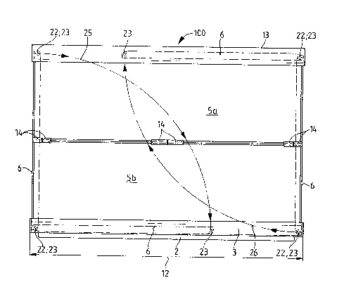
The folding box 100, shown in Figure 3, differs from the box of
Figure 1 in that its end walls 6 extend far beyond half of the box length
1~. Moreover, it also comprises a head frame 13~ and its longitudinal
walls are divided in the middle in the longitudinal direction, wherein the
two halves 5a, Sb of the longitudinal wall are connected to one another via
hinges 14.
The end walis 6 include the central locks 9 at their ends on
the head and foot sides. These locks comprise two hinge pin slides 16
which are inserted in the wall, arranged in a mirror-inverted manner and
are axially displaceable individually or jointly in a simultaneous manner
in the direction of the double arrow. These hinge pin slides 16 comprise a
2~7~9
25011-56
shaft-like handle part 18 which is movable in a slidiny manner in
a wall guide 17, the handle parts 18 being provided at their
facing ends with finger rings 19. Two hinge pins 8 are fastened
at an axial distance from one another on each slide at ~oot-like
slide webs 21 which face the head frame 13 and base frame 3,
respectively; the outer hinge pin ~3 projecting laterally relative
to the handle parts 18. In the box construction according to
Fig. 1, the outer hinge pins 8 engage in bore holes, not shown in
Fiy. 1, which are assigned to them in the longitudinal walls 6
and ensure the stable position of the folded-up box 1 by means of
this engagement.
In the construction of the folding box 100 according to
Fig. 3, the two hinge pins ~ of each slide 16 are inserted in
hinge eyes 22 o~ the base and head frame 3 and 13, respectively,
and U-shaped hinge pockets 23 enclosing the hinge eyes 22 in the
manner of a chamber. The hinge pockets 23 engaging over the
hinge eyes 22 are a fixed component part of the end wall 6,
; while the hinge eyes 22 are arranged at the head and base frame
~ 13, 3, respectively. Accordingly, the longitudinal walls, as
20 well as the end walls 5a, 5b and 6, respectively, are supported
in hinges so as to be movable in a swivelling manner. That is,
the longitudinal walls 5a, 5b are supported in hinges 24 of the
head frame and base frame 13, 3 as well as in the central hinges
14, and the end walls 6 are supported in the hinges formed by
the hinge eyes 22 and the hinge pockets 23.
When the end walls 6 are in the upright position shown
in Fig. 5 and the slides 16 are moved outward in the direction of
--10--
~7~sa~
25011-56
arrow 15, i.e. to the right or leEt, the folding box 100 is in
the folded state shown in Eig. 3 and cannot b~ collapsed as long
as the slides 15 occupy their locking position (as shown in Fig.
5). In order to collapse the box lO0, the upper locking of the
end wall 6, at left in Fig. 3, with the head frame 13 and the
lower locking of the end wall 6, at right in Fig. 3, Wi th the
base frame 3, respectively, are cancelled in that the head and
base slides 16 are moved toward one another and the hinge pins 14
are accordingl~ moved out of the hinge eyes 22 and hinge pockets
23. The end walls 6 are accordingly connected via the hinges,
with the base frame 3 and the head frame,respectively, only at
their lower and upper edge, respectively, whereas the other
hinges are unblocked or ~1nlocked, since the hinge pins are mo~ed
in out of their effective posi~ion by the displacement of the
slides 16.
The folding box lO0 can therefore be brought into the
space-saving folding position, as shown in Fig. 4, in that the
end wall 6, at left in Fig. 3, is first swivelled in the direction
of arrow 25 into the base frame 3 and then the end wall, at right
in Fig. 3, is swivelled upward in the direction of arrow 26 into
the head frame 13 (see the upper and lower positions of the end
walls 6 shown in dashed lines in Fig. 3). The longitudinal walls
5a, 5b can then be bent inward around their hinges l~ and, in
the folding position according to Fig. 3, the left end wall 6
lies in the base frame 3 and the right end wall 6 lies in position
parallel thereto on the longit~dinal walls 5a, 5b in the head
frame 13 which are bent inward and folded together.
--11--
.:
:
2~7~9
250~1-56
For better handling when folding and setting up the box
100, handle pockets 27 at the base ~rame 3, and at the head frame
13, open outward and simultaneously serve as support for the end
walls 6 so that occurrlng orces need not be absorbed via the
hinges. The end walls 6 are therefore provided with a recess 28
corresponding to the contour of the handle pockets 27.
The locks 9 and hinge pin slides 16 can be covered with
caps 29 ~see Fig. 6) and 31 (see Flg. 8), which can be inserted
into a wall groove 33 or the end wall 6 with catch projections
32 which close flush with the surface of the end wall 6 and
embrace the hinge pin 8 (see Fig. 101. To install in the end
wall 6, the cover plate 29 or 31 comprises recesses 34, 35
embracing the hinge eyes 22 and hinge pockets 23 or wall
projections. The cover plate 29, shown in Fig. 6, is provided
on the~ inside with two cylindrical projections 36 (see Fig. 7)
which are at a distance from one another such that they engage in
the finger rings 19 when the slides 16 are moved into their
locking position shown in Fig. 5 so that the cover plate 29
prevents an unloc~ing of the end walls 6 and accordingly a
collapsing of the box 100 which is desired in many cases. On
the other hand, the cover plate 31 has a longitudinal slot 37
which allows free access to the handle rings 19 after the cover
plate 31 has been placed on the lock 9 and accordingly permits
the desired displacement of the slides in the unblocking or
locking position. Since the end walls 6 have identical locks at
the top and bottom, it does not matter which side of the end walls
6 is inserted so as to face the base frame 3 or the head frame 13.
-12-
2~7~g
25011-56
~ s a result of the locking combined with the hinges,
one end wall can be swlvelled around the swivel axis arranged
in the area of the base frame 3 and deEined by the hinge pins 8
and the other end wall can be swivelled around the upper swivel
axis in the area of the hinge pins 8 of the head frame 13 when
the height of the end walls 6 exceeds half the length of the box,
so that the two end walls 6 lie in a parallel position with
respect to the base 2 when the box 100 is :Eolded together.
-12a-
. ~ ' , , .
2~17~9
Wh~1e the preferred embodlment o~ the lnvention have been
described in deta~l, mo~llficat~on and adaptat~ons thereof may be easily
undertaken w~thout depar-tlng from the splrlt and scope of the lnventlon as
delineated ln the appended c1a~ms.
~ .
-13-