Language selection

Search

Patent 2076646 Summary

Third-party information liability

Some of the information on this Web page has been provided by external sources. The Government of Canada is not responsible for the accuracy, reliability or currency of the information supplied by external sources. Users wishing to rely upon this information should consult directly with the source of the information. Content provided by external sources is not subject to official languages, privacy and accessibility requirements.

Claims and Abstract availability

Any discrepancies in the text and image of the Claims and Abstract are due to differing posting times. Text of the Claims and Abstract are posted:

  • At the time the application is open to public inspection;
  • At the time of issue of the patent (grant).
(12) Patent: (11) CA 2076646
(54) English Title: EAVES CLADDING
(54) French Title: RECOUVREMENT POUR DEBORD DE TOIT
Status: Expired and beyond the Period of Reversal
Bibliographic Data
(51) International Patent Classification (IPC):
  • E04D 13/15 (2006.01)
  • E04D 1/30 (2006.01)
  • E04D 3/36 (2006.01)
(72) Inventors :
  • LAMBERTI, ERHARD (Germany)
(73) Owners :
  • ERHARD LAMBERTI
(71) Applicants :
(74) Agent: SMART & BIGGAR LP
(74) Associate agent:
(45) Issued: 1995-02-28
(86) PCT Filing Date: 1990-12-12
(87) Open to Public Inspection: 1991-06-28
Examination requested: 1992-08-21
Availability of licence: N/A
Dedicated to the Public: N/A
(25) Language of filing: English

Patent Cooperation Treaty (PCT): Yes
(86) PCT Filing Number: PCT/DE1990/000958
(87) International Publication Number: WO 1991010025
(85) National Entry: 1992-08-21

(30) Application Priority Data:
Application No. Country/Territory Date
P 39 43 087.1 (Germany) 1989-12-27

Abstracts

English Abstract


The invention relates to a covering for the raised surrounding of a roof
having holders (1) and covering profiles (11), in which the single-piece and
angle shaped holders (1) possess flat surfaces (5, 6) on their shanks (3, 4), which
externally grip in close contact over the end borders (9, 10) of the covering
profiles (11) and hold them firmly in position against the roof surround.
The covering for the raised surrounding edge of a roof is extremely simple to
assemble because, after the mounting and adjustment of the holder (1), the end
of the covering profile (11) is pushed in simply behind the side surfaces of theshanks of the holder (1), by which means any extra work of fastening the profile(11) to the border of the roof is rendered superfluous.


Claims

Note: Claims are shown in the official language in which they were submitted.

The embodiments of the invention in which an exclusive property
or privilege is claimed are defined as follows:
1. A covering for a raised surrounding edge of a roof of
a building, said building having a wall with an outer surface,
said covering comprising:
covering profiles for arrangement end to end alongside
one another with vertical joints therebetween, said covering
profiles having a vertical web with an inner side and an outer
side, said vertical webs provided on their inner side with spacer
profiles for bearing against said outside surface of said wall
to space said vertical webs a short distance from said outer
surface of said wall, said cover profiles having a flange running
at an acute angle to said vertical web for gripping over said
roof edge; and
single-piece holders conforming to the cross-sectional
shape of said covering profiles, said holders for fastening to
said building and having, in cross-section, an inwardly-directed
recess portion with projecting flanges, said holders being
fastened to said building by fastening means accommodated within
said recess portions, said projecting flanges for engaging from
said outer side said ends of said covering profiles.
2. A covering for a raised surrounding edge of a roof as
claimed in claim 1 wherein said holders are provided with
pressure screws in said recess portions for adjusting the
position of said holders.
3. A covering for a raised surrounding edge of a roof as
claimed in claims 1 or 2 further comprising external cover strips
for said recess portions of said holders.

Description

Note: Descriptions are shown in the official language in which they were submitted.


2 0 7 6 6 4 6 05072-12 JWA:jy
EAVES CLADDING
The present invention relates to a covering for the raised
surrounding edge of a roof.
A covering of this type for the raised surrounding edge of a roof
is already known from the Prospects "GIEBELER-Flachdachabschluss
Typ G-FA" of the Company Giebeler KG in Wiesbaden, in which
holders fastened to the raised surrounding edge of the roof are
provided for holding the covering profiles apart from each other
by means of holder angles, said holders having shanks disposed
at an acute angle in relation to each other to form a U-shaped
cross-section. The free ends of the flanges of the U-shaped
cross shanks serve as support surfaces for the covering profile
and the web of the cross-section serves as the fastening base for
fastening screws which engage in the holder angles. The covering
profiles are pushed into the holders. However, the erection and
the assembling of this covering for the raised surrounding edge
of a roof is accompanied by a relatively great expenditure of
effort.
According to an aspect of the present invention, there is
provided a covering for a raised surrounding edge of a roof of
a building, said building having a wall with an outer surface,
said covering comprising: covering profiles for arrangement end
to end alongside one another with vertical joints therebetween,
said covering profiles having a vertical web with an inner side
and an outer side, said vertical webs provided on their inner
--
~l
~""
l~q

2076646
- la - 05072-12 JWA:jy
side with spacer profiles for bearing against said outside
surface of said wall to space said vertical webs a short distance
from said outer surface of said wall, said cover profiles having
a flange running at an acute angle to said vertical web for
gripping over said roof edge; and single-piece holders conforming
to the cross-sectional shape of said covering profiles, said
holders for fastening to said building and having, in cross-
section, an inwardly-directed recess portion with projecting
flanges, said holders being fastened to said building by
fastening means accommodated within said recess portions, said
projecting flanges for engaging from said outer side said ends
of said covering profiles.
The present invention is therefore based upon the problem of
designing a covering of the type under discussion for the raised
surrounding edge of a roof in such a way that it is especially
easy to fabricate, may be readily assembled and, if the need
should arise, may be just as readily disassembled.
The solution to this problem is based upon the fact that the
holders are constructed in one piece, have a hat-shaped cross-
section, engage in the vertical joints between the ends of the
covering profiles by means of the inwardly-directed recesses for
accommodation of the fastening means and cover over the outsides
of the ends of the covering profiles by means of their projecting
flanges. Under these conditions, the covering profiles are

2076646
- lb - 05072-12 J~A:jy
provided on the inner side of their vertical webs with spacer
profiles which bear against the outside surface of the wall of
the building.
//~/
.. , ~4 , ,

20766~6
-- 2
ihQnfll ~ok~ing devices, ~ olde~ angles and t~e l~ke, can be dispensed
~nth. l~e erlds of the co~e~lg pro~les ~re overIapped on ~e otttside by ~e
projec~ng f~ex of ~e holder and ar-e thus held f;rmly in posi~on. The
application of ~e ~o~e~g for t~e raised ~ 0~ in~ edge of a roof is
co~cPphally simple and ~antees an ~de~ ~ csemb~y by less-skilled
workers without ha~ g to call upon technical ~e.-ls, for ~e reason that the
~orm~rly-f~ ced compli~te~l assemhl;n~ of holder an~les, holders, ver~ joint
co~nect;on~ and t~e like, i~ no longer ne.;~ s~y. If re~uired, f~tlrin~ s~!p~5 to
the roof ~t ~ome later stage, the CO~ ;L~ profiles can be Iemoved and
s~bsequently be repl~ced in posi~;o n
Pa~ticular forms of embo~lim~n~ of the ilLv~LLLLon are objects of the Patent Claims
2 and 3.
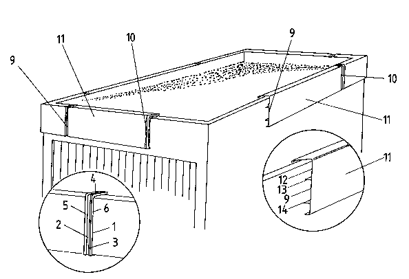
An einbo~ ent of ~he in~enUon to be fiiCc~se~ eater deta:~s in whatfollows is depictecl in the d~a~ngs, in which:
~ig. 1 is a cuv~llg ~ffi~e~l to the raisecl su~ n~lin~ edge of a ~at roof
wi~ two deta;ls shown on an erl~rged ~cale and
Fig. ~ ~s a holde~ and one end of a ~"~"t; profile of the cove~g s~own
in Fig. 1.
'rhe single-piece, angle shaped holde~ 1 hav ng a hat-like config~-r~hon poss~sc~
a recess ~ in bo~ of its shan~s 3 ancl 4, where it i~ ~ffiYe~ to the roof ~u~.o~d
by means of the f~t~ meaI~s prov~ded in said recess. With the use of the
crews 15, li~. ise disposed in ~his recess 2, the po~-hon of ~e holder
1 may ~e adjusted in ~el~o~l to the o~ts;~1e surhce of the wall of ~he b~ in~
Then, a c~v~t~g profile 11, b~ way of ~y~mI~le when ~vOil~Lg froIn the left-

2 0 7 6 !~ L~ fi
hand end towards the right-hand end, is pushed into position un~h its end 9
behind the inner ~ide 8 of the ~ange 6 of the holder 1. Following ~his, ~e next
holder 1 ~s pushed onto ~e other end lO of the co~ ng profile 11 so that the
inne~ side 7 of its flange 5 rests against the outer side of the co~ve..l~g profile 11,
and then it is fastened to ~e roof ~u~lo~md and adju~te~ in posi~on by mea~s
of the ~r..,s~e ~crews ~5 lnr~terl iII the recess ~. Oxl ~he inner surface 1~ of the
coverin~ profile 11 there are spacer profiles 13, 14 for holding it at a short
~ict~nt~ away ~om the outer s~lrf~e of the roof su~.u.md. After completion o~
the ~cspn~bly~ the rece~ 2 is provided with a cover ~trip 17.
SpecialJy fabri~te~l corner~;uve~g profiles are first mounted exac~y vertical~y,and then ~e ho~ters 1 re~L~l to ir~stially and the covering profile~ 11 are
mounted exactly vertic~lly on the sides of said co~ner profiles. PL(,ceeii..~ along
alway~ towa~d~ the cen~e point of ~e ~oof ~lrr LLd, suc~sive cove~ing
p~ofiles 11 ~nd-holders 1 are ~im-.lt~n~ou~ly mous~ted, as previously d~c~h~
With the aid of th~ built-in ~e~s~ screws 1~ in the holder 1, an exac~y ~l;~e~
C~JVe~LL~ for the raLsed SU~ .ding edge of a roof may be achieved.

Representative Drawing
A single figure which represents the drawing illustrating the invention.
Administrative Status

2024-08-01:As part of the Next Generation Patents (NGP) transition, the Canadian Patents Database (CPD) now contains a more detailed Event History, which replicates the Event Log of our new back-office solution.

Please note that "Inactive:" events refers to events no longer in use in our new back-office solution.

For a clearer understanding of the status of the application/patent presented on this page, the site Disclaimer , as well as the definitions for Patent , Event History , Maintenance Fee  and Payment History  should be consulted.

Event History

Description Date
Inactive: Adhoc Request Documented 1996-12-12
Time Limit for Reversal Expired 1996-06-12
Letter Sent 1995-12-12
Grant by Issuance 1995-02-28
Request for Examination Requirements Determined Compliant 1992-08-21
All Requirements for Examination Determined Compliant 1992-08-21
Application Published (Open to Public Inspection) 1991-06-28

Abandonment History

There is no abandonment history.

Owners on Record

Note: Records showing the ownership history in alphabetical order.

Current Owners on Record
ERHARD LAMBERTI
Past Owners on Record
None
Past Owners that do not appear in the "Owners on Record" listing will appear in other documentation within the application.
Documents

To view selected files, please enter reCAPTCHA code :


To view images, click a link in the Document Description column. To download the documents, select one or more checkboxes in the first column and then click the "Download Selected in PDF format (Zip Archive)" or the "Download Selected as Single PDF" button.

List of published and non-published patent-specific documents on the CPD .

If you have any difficulty accessing content, you can call the Client Service Centre at 1-866-997-1936 or send them an e-mail at CIPO Client Service Centre.


Document
Description 
Date
(yyyy-mm-dd) 
Number of pages   Size of Image (KB) 
Abstract 1995-02-28 1 23
Cover Page 1995-02-28 1 18
Claims 1995-02-28 1 41
Abstract 1995-02-28 1 23
Description 1995-02-28 5 158
Drawings 1995-02-28 2 31
Representative drawing 1999-08-11 1 18
Fees 1994-12-05 1 52
Fees 1993-11-22 1 43
Fees 1992-11-19 1 47
Examiner Requisition 1994-01-10 1 57
International preliminary examination report 1992-08-21 20 573
Courtesy - Office Letter 1993-03-24 1 31
PCT Correspondence 1994-12-19 2 56
Prosecution correspondence 1994-07-07 2 57