Language selection

Search

Patent 2077026 Summary

Third-party information liability

Some of the information on this Web page has been provided by external sources. The Government of Canada is not responsible for the accuracy, reliability or currency of the information supplied by external sources. Users wishing to rely upon this information should consult directly with the source of the information. Content provided by external sources is not subject to official languages, privacy and accessibility requirements.

Claims and Abstract availability

Any discrepancies in the text and image of the Claims and Abstract are due to differing posting times. Text of the Claims and Abstract are posted:

  • At the time the application is open to public inspection;
  • At the time of issue of the patent (grant).
(12) Patent Application: (11) CA 2077026
(54) English Title: ROTATION PROMOTING MEANS FOR ROTATING SHAFT AND POWER GENERATION SYSTEM PROVIDED WITH SAID ROTATION PROMOTING MEANS
(54) French Title: DISPOSITIF FAVORISANT LA ROTATION D'UN ARBRE TOURNANT ET GENERATEUR D'ELECTRICITE POUR ALIMENTER LE DISPOSITIF EN QUESTION
Status: Deemed Abandoned and Beyond the Period of Reinstatement - Pending Response to Notice of Disregarded Communication
Bibliographic Data
(51) International Patent Classification (IPC):
  • F03G 7/10 (2006.01)
  • F03G 3/00 (2006.01)
(72) Inventors :
  • SUEHIRO, TAKEO (Japan)
(73) Owners :
  • TAKEO SUEHIRO
(71) Applicants :
(74) Agent: RICHES, MCKENZIE & HERBERT LLP
(74) Associate agent:
(45) Issued:
(22) Filed Date: 1992-08-27
(41) Open to Public Inspection: 1993-06-28
Availability of licence: N/A
Dedicated to the Public: N/A
(25) Language of filing: English

Patent Cooperation Treaty (PCT): No

(30) Application Priority Data:
Application No. Country/Territory Date
358010/1991 (Japan) 1991-12-27
87461/1992 (Japan) 1992-03-12

Abstracts

English Abstract


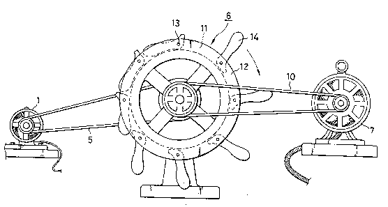
ABSTRACT OF THE DISCLOSURE
The object of the present invention is to provide
a power generation system industrially cost-effective, in
which a power generator is rotated by a motor by utilizing
gravitational energy, and also to provide rotation promoting
means for a rotating shaft to be used in said power
generation system.
The arrangement according to the present invention is
characterized in that a plurality of weights are rotatably
mounted with spacings on outer periphery of a rotating
wheel, which is mounted on a rotating shaft, that said
weights are set in open position and project outwardly when
moving down in rotating direction, and the weights are set
in closed position when moving up in rotating direction,
and that there are provided a motor for rotating said
rotating shaft and a power generator for generating
electric power when rotated by said rotating shaft.
- 8 -


Claims

Note: Claims are shown in the official language in which they were submitted.


WHAT IS CLAIMED IS:
1. Rotation promoting means for a rotating shaft,
characterized in that a plurality of weights are rotatably
mounted with spacings on outer periphery of a rotating
wheel, which is mounted on a rotating shaft, that said
weights are set in open position and project outwardly when
moving down in rotating direction, and the weights are set
in closed position when moving up in rotating direction.
2. Rotation promoting means for a rotating shaft
according to Claim 1, wherein a recessed groove is formed
on outer periphery of said rotating wheel, and said
weights are supported on a shaft installed on said recessed
groove.
3. A power generation system, characterized in
that a plurality of weights are rotatably mounted with
spacings on outer periphery of a rotating wheel, which is
mounted on a rotating shaft, that said weights are set in
open position and project outwardly when moving down in
rotating direction, and the weights are set in closed
position when moving up in rotating direction, and that
there are provided a motor for rotating said rotating
shaft and a power generator for generating electric power
when rotated by said rotating shaft.
- 7 -

Description

Note: Descriptions are shown in the official language in which they were submitted.


iY'~
TITLE OF THE INVENTION
Rotation promoting means for rotating shaft and power
generation system provided with said rotation promoting
means.
BACKGROUND OF THE INVENTION
The present invention relates to rotation promoting
means for accelerating rotation of a rotating shaft, and
also to a power generation system provided with said
rotation promoting means.
In Japan, electric power is generated by nuclear,
hydroelectric, and thermoelectric power plants. Despite of
severe controversy from safety reasons, the Government has
an intention to rely on nuclear power generation because it
is more a'dvantageous in cost than thermoelectric and
hydroelectric power generation at present.
In obtaining energy through rotation of a power
generator directly rotated by a motor, there is obviously
no benefit viewed from the law of energy conservation.
Thus, no basic concept is known yet to obtain electric
power industrially through rotation of a power generator
by a motor.
SUMMARY OF THE INVENTION
It is an object of the present invention to provide
,' ' ', ~ ' , ' .
. . .

2~
rotation promoting means for a rotating shaft, which is
operated by gravitational force without supplying energy
from outside.
It is another object of the invention to provide a
power generation system equipped with rota~ion promoting
means, which is operated ~y gravitational force.
The arrangement of the present invention is character-
ized in that a plurality of weights are rotatably mounted
with spacings on outer periphery of a rotating wheel, which
is mounted on a rotating shaft, that said weights are set
in open position and project outwardly when moving down
in rotating direction, and the weights are set in closed
position when moving up in rotating direction, and that
there are provided a motor for rotating said rotating shaft
and a power generator for generating electric power when
rotated by said rotating shaft.
After all, the present invention is based on a
principle that the rotating shaft is equipped with means
for promoting rotation by gravitational force when a power
eenerator is directly rotated by a motor, and surplus energy
is obtained by gravitational force and power is generated
in economically and industrially feasible manner.
The above and other obJects and advantages of the
invention will become more apparent from the following
description.
,~ :

BRIEF DESCRIPTION OF THE DRAWINGS
Fig. 1 is a general view schematically illustrating an
embodiment of the present invention; and
Fig. 2 is a side view schematically illustrating the
above embodiment of the invention.
DETAILED DESCRIPTION OF THE PREFERRED EMBODIMENT
In the following, description will be given on an
embodiment of the present invention in connection with the
drawings.
The embodiment comprises a starting motor 1, a belt
(chain) 5 stretched between a small diameter pulley 2 of
said starting motor 1 and a large diameter pulley 4 of a
rotating'shaft 3, rotation promoting means 6 mounted on the
rotating shaft 3 on both sides of said large diameter pulley
4, and a belt (chain) 10 stretched between a small diameter
pulley 8 of a power generator 7 and a large diameter pulley
9 of the rotating shaft 3.
As shown in Fig. 1 and Fig. 2, the rotation promoting
means is designed in such arrange~ent that a plurality o~
weights 111 are rotatably supported on a plurality of shafts
13, which are mounted on a recessed groove 11 on outer
periphery of a rotating wheel 12. Therefore, when the
wheel is rotated in the arrow direction in Fig. 1 and the

weights are moved down in the rotating direction, they are
set in open position by self-weigh-t and project outwardly.
When the weights are moved up in the rotating direction,
they are set in closed position and are brought into contact
with the recessed groove 11. As the result, the weights on
the right side of Fig. 1 mounted on the wheel 12 are in
open position and the weights on the other side are in
closed position at all times. Thus, rotary moment is
generated, and the rotation of the rotating shaft 3 is
promoted.
In the above embodiment, the rotation promoting means 6
are mounted one on each side of the shaft, while more than
one, e.g. 10 each, of such means may be provided, and the
number of such means may be properly selected according to
the size'of the rotation promoting means and electric power
to be generated.
The rotating shaft 3 of the rotation promoting means 6
is supported by bearings 16 and 16'. The power generator 7
is rotated through the belt 10, which connects the large
diameter pulley 9 mounted on one end of the rotating shaft 3
and the small diameter pulley 8 of the power generator 7,
and power is generated.
In the above embodiment, a recessed groove 11 is formed
on outer periphery of the wheel 12 so that the weights 1~1
are brought into contact with and stopped by said recessed

groove 11. However, the invention is not limited to this,
and stoppers may be used, for example.
In the above embodiment, the pulley 2 mounted on the
rotating shaft of the motor is designed with small diameter
and the pulley 4 mounted on the rotating shaft 3 is designed
with large diameter. The reason for this is to slow down
the rotating speed of the rotating shaft because, if the
rotating speed of the shaft is too fast, all weights may be
set in open positions by centrifugal force.
Because the rotating shaft 3 is also rotated by the
rotation promoting means 6, there is no need that the
starting motor 1 is operated at all times, and the motor may
be turned on and off with a certain time interval.
The application of the rotation promoting means 6 of
the present invention is not limited to the rotation of the
power generator, and it may be used for rotating any type of
wheels. In summing up, it can be used for any application
for promoting and accelerating the rotation of a rotating
wheel by mounting on a rotating shaft of the rotating
wheel.
Next, description will be given on the operating
principle of the present invention wikh the above arrange-
ment.
When the rotating shaft 3 is rotated by the rotation of
the starting motor 1 through the belt 5, the wheel 12 is

rotated as shown in the figure. The weights 14 on the wheel
12 are set in open position when the weights are moving
downward, and the weights are set in closed position when
moving up. Thus, rotating force generated by rotary moment
is given to the rotating shaft 3, and the rotation is
promoted. ~hen the rotating shaft 3 is rotated, the power
generator 7 is rotated through the belt (chain) 10, and
electric power is generated.
According to the present invention, a force to push the
rotating shaft downward is applied by the principle of
seesaw and this force is converted to surplus electric power
generated by energy other than the motor.
As described above, it is possible according to the
present invention to promote the rotation of the rotating
shaft bedause the rotation promoting means operated by
gravitational force are provided without supplying energy
from outside. Thus, electric power with higher energy can
be generated than the energy given to the power generator
by the motor. This surplus energy corresponds to the energy
given by the gravitational force, which is supplied free of
charge.
- 6 -

Representative Drawing
A single figure which represents the drawing illustrating the invention.
Administrative Status

2024-08-01:As part of the Next Generation Patents (NGP) transition, the Canadian Patents Database (CPD) now contains a more detailed Event History, which replicates the Event Log of our new back-office solution.

Please note that "Inactive:" events refers to events no longer in use in our new back-office solution.

For a clearer understanding of the status of the application/patent presented on this page, the site Disclaimer , as well as the definitions for Patent , Event History , Maintenance Fee  and Payment History  should be consulted.

Event History

Description Date
Inactive: IPC from MCD 2006-03-11
Time Limit for Reversal Expired 1998-08-27
Application Not Reinstated by Deadline 1998-08-27
Deemed Abandoned - Failure to Respond to Maintenance Fee Notice 1997-08-27
Application Published (Open to Public Inspection) 1993-06-28

Abandonment History

Abandonment Date Reason Reinstatement Date
1997-08-27
Owners on Record

Note: Records showing the ownership history in alphabetical order.

Current Owners on Record
TAKEO SUEHIRO
Past Owners on Record
None
Past Owners that do not appear in the "Owners on Record" listing will appear in other documentation within the application.
Documents

To view selected files, please enter reCAPTCHA code :


To view images, click a link in the Document Description column. To download the documents, select one or more checkboxes in the first column and then click the "Download Selected in PDF format (Zip Archive)" or the "Download Selected as Single PDF" button.

List of published and non-published patent-specific documents on the CPD .

If you have any difficulty accessing content, you can call the Client Service Centre at 1-866-997-1936 or send them an e-mail at CIPO Client Service Centre.


Document
Description 
Date
(yyyy-mm-dd) 
Number of pages   Size of Image (KB) 
Drawings 1993-06-28 2 49
Abstract 1993-06-28 1 20
Claims 1993-06-28 1 26
Cover Page 1993-06-28 1 16
Descriptions 1993-06-28 6 158
Representative drawing 1999-06-17 1 18
Courtesy - Abandonment Letter (Maintenance Fee) 1997-10-06 1 188
Fees 1996-08-09 1 40
Fees 1995-07-12 1 42
Fees 1994-08-05 1 35