Language selection

Search

Patent 2077041 Summary

Third-party information liability

Some of the information on this Web page has been provided by external sources. The Government of Canada is not responsible for the accuracy, reliability or currency of the information supplied by external sources. Users wishing to rely upon this information should consult directly with the source of the information. Content provided by external sources is not subject to official languages, privacy and accessibility requirements.

Claims and Abstract availability

Any discrepancies in the text and image of the Claims and Abstract are due to differing posting times. Text of the Claims and Abstract are posted:

  • At the time the application is open to public inspection;
  • At the time of issue of the patent (grant).
(12) Patent Application: (11) CA 2077041
(54) English Title: INTERCONNECTABLE NUMISMATIC CONTAINERS
(54) French Title: CONTENEURS NUMISMATIQUES EMPILABLES
Status: Deemed Abandoned and Beyond the Period of Reinstatement - Pending Response to Notice of Disregarded Communication
Bibliographic Data
(51) International Patent Classification (IPC):
  • G07D 9/06 (2006.01)
  • A45C 1/10 (2006.01)
  • G07D 9/00 (2006.01)
(72) Inventors :
  • JOHNSON, DENNIS A. (Canada)
(73) Owners :
  • DENNIS A. JOHNSON
(71) Applicants :
  • DENNIS A. JOHNSON (Canada)
(74) Agent: J. T. KERFOOTKERFOOT, J. T.
(74) Associate agent:
(45) Issued:
(22) Filed Date: 1992-08-27
(41) Open to Public Inspection: 1994-02-28
Examination requested: 1992-12-23
Availability of licence: N/A
Dedicated to the Public: N/A
(25) Language of filing: English

Patent Cooperation Treaty (PCT): No

(30) Application Priority Data: None

Abstracts

English Abstract


INTERCONNECTABLE NUMISMATIC CONTAINERS
ABSTRACT OF THE DISCLOSURE
An integral, stackable, numismatic container formed of a
resilient, plastic material is provided. The container comprises
an open-latticed cylinder with upper and lower sections hingedly
connected to one another. A fastener is provided to secure upper
and lower sections. The cylinders are confined between two
rectangular opposed end walls. The end walls are provided with
projections and recesses so that the containers may be stacked upon
one another.


Claims

Note: Claims are shown in the official language in which they were submitted.

THE EMBODIMENTS OF THE INVENTION IN WHICH AN EXCLUSIVE PROPERTY OR
PRIVILEGE ARE CLAIMED ARE DEFINED AS FOLLOWS;
1. A container for numismatic objects which comprises;
an elongate open-latticed cylinder, comprised of upper and
lower sections, said sections being hingedly connected at
their mid-points one to another;
fastener means for securing said upper and lower sections,
said fastener means being diametrically opposed to said hinge
means;
a pair of rectangular end walls, being associated with said
cylinders and perpendicularly disposed thereto; and
means, associated with the end walls for releasably
interlocking them whereby a plurality of containers may be
stacked in vertical or horizontal array.
2. A container for numismatic objects which comprises;
a pair of elongate open-latticed cylinders, said cylinders
comprising upper and lower sections contiguous longitudinally
with one another, one of the upper sections being hingedly
connected to one of the lower sections, and the opposed upper
and lower sections being releasably secured to one another;
a pair of end walls being associated with said cylinders and
perpendicularly disposed thereto; and
means associated with said end walls for releasably
interlocking them whereby a plurality of containers may be
stacked in vertical or horizontal array.

Description

Note: Descriptions are shown in the official language in which they were submitted.


2~
FIELD OF THE INVENTION
The present invention relates to an stackable container
tailored preferably for numlsmatic ob~ects or the like.
BACKGROUND OF THE INVENTION
It is well known in the art to pr,ovide coin holders. For
example, in U. S. patent 4,240,544, there is disclosed a coin
holder which is formed of two semi-cylindrical sections connected
by means of a hinge. End walls are provided to stop the coins from
dropping out of the ends of the holder. In U.S. patent 4,240, 523
there is disclosed a similar holder, the difference between the two
apparently being that the '544 holder is dimensioned a smaller size
than the coins, so as to resiliently grip them in place. Whereas,
in the '523 patent the holder relies upon the provision of an
integral fastener. Although, again the is holder is dimensioned
smaller than the coln. A third prior art coin holder, which is in
`; current usage, relies upon a crescent-shaped holder formed of
resilient material. The coins are forced into place by splaying
the edges apart. This holder displays the disadvantage that it is
awkward both to insert and to extract the coins.
Deleteriously, all these prior art devices are of a temporary
durability. Another disadvantage of such units is that they lack
stability in terms of rolling and stackability.
:.
~`1 SUMMARY OF THE INVENTION
. ......................................................................... ~
In accordance with the present invention there is provided a
coin holder functional to contain a plurality of coins, discs,
counters or the like. Furthermore, the container is adapted for
stacking to thereby decrease the amount of coin storage space
required. An additional advantage of the present container is that
the stacking means are further operative to prevent the container
from rolling, thereby imparting stability thereto. Further
advantages of the present invention rely on the durability of the
container, because unliXe the prior art devices, there is no
utilization of a force fit which would soon result in destruction
.

2~7~V~.
of the resilient plastic material of construction.
In a first broad aspec~
,'~ .
DESCRIPTION OF THE DRAWINGS
Figure 1 is a perspective view of the container of the instant
invention in the closed position.
Figure 2 is a side view of the container of figure 1.
Figure 3 is a sectional view of the container of figure 1.
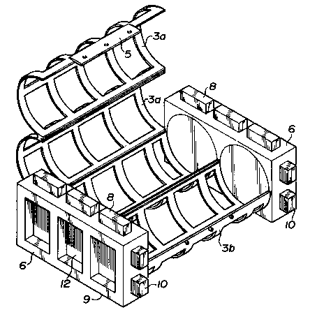
Figure 4 is a perspective view of the container of figure 1 in the
open position.
DESCRIPTION OF THE PREFERRED EMBODIMENT
Having reference to the accompanying drawings there is shown
the container 1. The container 1 comprises open-latticed cylinders
3 having upper and lower semi-circular sections 3a and 3b. The
sections 3a and 3b are adapted for opening and closing by means of
a hinge 4. Opposite the hinge 4, there is provided a fastener 5.
End walls 6 , which are adapted to receive the cylinders 3 are
positioned at each end of the cylinders 3. A recess 7 formed in
the walls 6 mates with a pro~ection ( not shown) in the cylinders
3. The end walls 6 are provided with interconnectable vertical
pro~ections 8 which mate with corresponding vertical recesses 9
formed in the end walls. Further, the side walls are provided with
horizontal pro~ectlons 10 which mate with corresponding recesses
(not shown) in the side of the end walls 6. Pro~ections 13 mate
with recesses 12 in the end walls. The container 1 could be formed
of wood, metal or the like but preferably would be formed of a
resilient plastlc materlal. ^
''.
.
)
:.

Representative Drawing
A single figure which represents the drawing illustrating the invention.
Administrative Status

2024-08-01:As part of the Next Generation Patents (NGP) transition, the Canadian Patents Database (CPD) now contains a more detailed Event History, which replicates the Event Log of our new back-office solution.

Please note that "Inactive:" events refers to events no longer in use in our new back-office solution.

For a clearer understanding of the status of the application/patent presented on this page, the site Disclaimer , as well as the definitions for Patent , Event History , Maintenance Fee  and Payment History  should be consulted.

Event History

Description Date
Inactive: IPC from MCD 2006-03-11
Inactive: Inventor deleted 2002-08-14
Time Limit for Reversal Expired 1996-02-27
Application Not Reinstated by Deadline 1996-02-27
Deemed Abandoned - Failure to Respond to Maintenance Fee Notice 1995-08-28
Inactive: Adhoc Request Documented 1995-08-28
Application Published (Open to Public Inspection) 1994-02-28
All Requirements for Examination Determined Compliant 1992-12-23
Request for Examination Requirements Determined Compliant 1992-12-23

Abandonment History

Abandonment Date Reason Reinstatement Date
1995-08-28

Maintenance Fee

The last payment was received on 

Note : If the full payment has not been received on or before the date indicated, a further fee may be required which may be one of the following

  • the reinstatement fee;
  • the late payment fee; or
  • additional fee to reverse deemed expiry.

Please refer to the CIPO Patent Fees web page to see all current fee amounts.

Fee History

Fee Type Anniversary Year Due Date Paid Date
MF (application, 2nd anniv.) - small 02 1994-08-29
Owners on Record

Note: Records showing the ownership history in alphabetical order.

Current Owners on Record
DENNIS A. JOHNSON
Past Owners on Record
None
Past Owners that do not appear in the "Owners on Record" listing will appear in other documentation within the application.
Documents

To view selected files, please enter reCAPTCHA code :


To view images, click a link in the Document Description column. To download the documents, select one or more checkboxes in the first column and then click the "Download Selected in PDF format (Zip Archive)" or the "Download Selected as Single PDF" button.

List of published and non-published patent-specific documents on the CPD .

If you have any difficulty accessing content, you can call the Client Service Centre at 1-866-997-1936 or send them an e-mail at CIPO Client Service Centre.


Document
Description 
Date
(yyyy-mm-dd) 
Number of pages   Size of Image (KB) 
Cover Page 1994-02-28 1 25
Claims 1994-02-28 1 32
Drawings 1994-02-28 2 95
Abstract 1994-02-28 1 15
Descriptions 1994-02-28 2 81
Representative drawing 1998-08-17 1 31
Fees 1994-08-16 1 25
Prosecution correspondence 1992-12-23 1 36
PCT Correspondence 1993-09-10 1 56
Courtesy - Office Letter 1993-04-01 1 41