Note: Descriptions are shown in the official language in which they were submitted.
-1_
CONNECTOR FOR CONNECTINC3 AN ELECTRICAL C LE
This invention relates to a connector for connecting
an electrical cable, and more particularly a non-metallic
clad cable, in an opening in a wall, such as an opening
formed by the removal of a knock-out plug in a wall of an
electrical outlet box.
Such a connector is conventionally provided in
which, after removal of a knock-out plug from a wall in the
electrical outlet box, the connector is securely mounted in
the opening formed thereby, with an end portion of an
electrical cable thereafter being disposed from outside the
electrical outlet box through the connector for electrical
connection of the wiring in this end portion of the
electrical cable, after it has been stripped, to an
electrical switch, outlet socket or other electrical device
disposed within the outlet box, the connector serving to
prevent chafing of the electrical cable against the edge of
the wall of the outlet box which defines the opening therein
and which could result, in operation, in an electrical
short-circuit. Such connectors conventionally also so grip
the electrical cable disposed therethrough that while the
electrical cable can readily be urged through the connector
in the direction from outside the electrical outlet box the
cable cannot subsequently be withdrawn in the opposite
direction, thereby operatively providing a strain relief
effect in that a force on the cable outside the outlet box
tending to withdraw the cable from the outlet box is
substantially prevented from being transmitted to the
connection between the stripped wiring in the end portion of
the cable and the terminals of the electrical device
installed within the box. This strain relief effect is,
CA 02077230 2002-07-30
- 2 -
of course, desirable, but during the disposition of the end
portion of the electrical cable through the connector the
electrician may insert an excessive length of the end
portion of the cable through the connector. It is a:
disadvantage of the conventional connectors as described
above that there is no quick and convenient arrangement for
partially withdrawing the end portion of the cable so that
only the desired length of cable projects through the
connector into the outlet box, and it is a primary object of
the present invention to provide a connector in which this
disadvantage is substantially overcome or mitigated.
In accordance with the present invention there is~
provided a connector for releasably connecting an electrical
cable in an opening in a wall, comprising a tubular portion
having a front end and a rear end, an outwardly projecting
flange at the front end of the tubular portion, a rear end
wall at the rear end of the tubular portion, outwardly
projecting ribbing on the tubular portion and spaced from
the flange for securing the connector within an opening in
a wall with the wall between the flange and ribbing, and an
aperture in the rear end wall for the passage of an
electrical cable therethrough. First and second
circumferentially spaced slots extend from the aperture in
the rear end wall to the front end of the tubular portion,
only the first slot of the first and second slots extending
fully through the connector so that at this first slot the
connector is circumferentially discontinuous, with the
connector at the second slot being of resiliently deformable
material whereby the width of the aperture in the rear end
wall may be increased by forcibly increasing the width of
the first slot with resultant resilient deformation of the
connector at the second slot. The ribbing comprises
~ ' CA 02077230 2002-07-30
- 2a
two diametrically opposed, circumferentially spaced ribs
each of which extends in a circumferential direction
partially around the tubular portion.
~t~~.~, y'~ ~~J
- 3 -
In order that the present invention may be more
clearly understood and more readily carried into effect the
same will now, by way of example, be more fully described
with reference to the accompanying drawings in which Fig. 1
is a side view of a connector according to a preferred
embodiment of the invention secured in an opening in a wall
and with an end portion of an electrical cable disposed
through the connector;
Fig. la is a view corresponding to Fig. 1 but showing an
intermediate stage in the mounting of the connector in the
opening in the wall;
Fig. 2 is an end view of the connector shown in Fig. 1 in
the direction of the arrow A:
Fig. 3 is a sectioned view of the connector on the line 3-3
in Fig. 2; and
Fig. 4 is a sectioned view of the connector on the line 4-4
in Fig. 2.
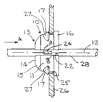
Referring to the drawings, 10 denotes generally a
connector comprising a tubular portion 11 which is of
generally cylindrical form having a longitudinal axis 12,
with at the rear end of the tubular portion 11 a rear end
wall 13 comprising a central transverse portion 14
surrounded by a frusto-conical portion 15. At the front end
of the tubular portion 11 is an outwardly projecting flange
16, and presented on the tubular portion 11 at a spaced
distance from the flange 16 is outwardly projecting ribbing
17 preferably comprising two diametrically opposed,
circumferentially spaced ribs each of which extends in a
circumferential direction partially around the tubular
portion 11.
- 4 -
The central portion 14 of the rear end wall 13 has
an aperture 18 which is preferably of elongated form and is
bounded by opposed jaws 19 each of which, as is most clearly
shown in Fig. 3, has an axial rear edge portion 20, and a
curvilinearly chamfered front edge portion 21 merging
smoothly into the associated rear edge portion 20.
A first slot 22 extends fully through the connector
l0 from the elongated aperture 18 across the frusto-conical
portion 15 of the rear end wall 13, the tubular portion 11
and the flange 16 so that at this first slot 22 the
connector 1o is circumferentially discontinuous, a second
slot 23 which is circumferentially spaced from and
preferably diametrically opposed to the first slot 22
extending from the aperture 18 across the frusto-conical
portion 15 of the rear end wall 13, and the tubular portion
11. In the preferred embodiment of the invention shown in
the drawings, however, this second slot 23 does not extend
through the tubular portion 11 but comprises, in the tubular
portion 11, a groove 23' in the inner face thereof, the wall
thickness of the tubular portion 11 being, in the preferred
embodiment, 0.075 inch with the depth of the groove 23'
being 0.050 inch so that the depth of the groove 23'
constitutes a major portion of the wall thickness of the
tubular portion 11. Thus, at the second slot 23 the two
parts of the connector l0 bounded by the slots 22 and 23 are
interconnected only by the flange 16 and the wall part 11'
of the tubular portion 11 outwardly of the groove 23'. At
the second groove 23 the flange 16 and this wall part 11' of
the tubular portion 11 are of a resiliently deformable
material, and in the preferred embodiment the connector 10
is integrally formed of a molded plastics material, this
plastics material being, for example, nylon so that, as is
hereinafter further described, the width of the aperture 18
between the opposed jaws 19 may be increased by forcibly
~~": ''~'''~4J
- 5 -
increasing the width of the first slot 22 by, for example,
inserting the blade 24 of a conventional screwdriver or a
coin into the first slot 22 and then twisting the blade 24
of the screwdriver or the coin as shown by the arrows B in
Fig. 1 with resultant resilient deformation of the flange 16
and said wall part 11' of the tubular portion 11 at the
second slot 23.
In operation, an opening 25 is provided in a wall
26, this opening 25 being formed, for example, by the
removal of a knock-out plug (not shown) in an electrical
outlet box. The connector 10 is then secured within this
opening 25, this securement of the connector 10 being
achieved by initially disposing the connector 10 from
outside the outlet box at an inclined angle through the
opening 25 as shown in Fig. 1a with one of the ribs 17 such
as, for example, the upper rib 17 as shown in Fig. 1a within
the outlet box. Thereafter, by applying a force to the
flange 16 from outside the outlet box the other rib 17 is
snapped through the opening 25 fully to install the
connector 10 within the opening 25 with the wall 26 between
the flange 16 and the ribs 17, the rear faces 27 of the ribs
17 being of tapered form to facilitate this snapping of the
appropriate ribs 17 through the opening 25.
An end portion 28 of a non-metallic clad electrical
cable is then urged from outside the outlet box through the
connector 10 and the aperture 18 therein with resilient
flexing of the central portion 14 of the rear end wall 13 in
the rearward direction, the curvilinearly chamfered front
edge portion 21 of each jaw 19 facilitating this insertion
of the end portion 28 of the electrical cable through the
aperture 18, but the edges 29 at the junctions of the axial
rear edge portions 20 of the jaws 19 and the central portion
14 substantially preventing withdrawal of the end portion 28
- 6 -
of the electrical cable in the opposite direction since
urging this end portion 28 of the electrical cable in said
opposite direction results in resilient flexing of the
central portion 14 in the forward direction thereby causing
the edges 29 at the junctions of the portions 20 of the jaws
19 and the central portion 14 more securely to grip the
electrical cable. The connector 10 may alternatively
be installed after the end portion 28 of the electrical
cable has been disposed through the opening 25 in the wall
26 by forcibly increasing the width of the first slot 22
with resultant resilient deformation of the flange 16 and
said wall part 1l' of the tubular portion 11 at the second
slot 23, and outside of the outlet box urging the electrical
cable through the first slot 22, the connector 10 thereafter
being secured through the opening 25 in the manner described
above.
If, however, the electrician has inserted an
excessive length of the end portion 28 of the electrical
cable into the outlet box the blade 24 of a screwdriver or
a coin may be inserted in the first slot 22 and twisted as
hereinbefore described in order sufficiently to increase the
width of the aperture 18 between the jaws 19 as to permit
partial, or complete, withdrawal of the end portion 28 of
the electrical cable as desired.
Generally, in new building construction electrical
outlet boxes are installed with the end portions of
electrical cables disposed through connectors mounted in
knock-out openings in the outlet boxes, and wall panelling
is then installed with associated plastering being performed
before the electrical switches, outlet sockets or other
electrical devices are mounted in the outlet boxes and are
electrically connected to the wiring in the end portions of
the electrical cables. If after the wall panelling has been
r~ ~ r ~ u'~
_ 7 _
installed and the associated plastering has been performed
the electrician discovers that an excessive length of the
end portion of an electrical cable is disposed within an
outlet box this end portion of the electrical cable can be
partially withdrawn from the outlet box in the manner
hereinbefore described but by pushing the end portion of the
electrical cable from within the outlet box, rather than by
pulling the end portion of the electrical cable from outside
the outlet box, since of course the wall panelling and
associated plastering renders inaccessible the end portion
of the electrical cable outside the outlet box.
If it is desired to remove the connector 10 from the
opening 25 in the wall 26 the end portion 28 of the
electrical cable is completely withdrawn from the aperture
18 as described above, and then by pushing from inside the
outlet box on one of the ribs 17 this rib 17 is snapped out
of the opening 25 so that the connector 10 is then in the
condition shown in Fig. 1a and the connector may be removed
and re-used, this snapping of the ribs 17 out of the opening
25 being permitted by the ribs 17 each having a face 30
directed towards the flange 16 which has a rearward rake
preferably at an angle of approximately 15° as indicated in
Fig. 3.
If desired, the connector 10 including of course the
aperture 18 may be so dimensioned relative to the electrical
cable that two or more such electrical cables may be
disposed therethrough as shown in chain-dotted lines in Fig.
1a.
While in the preferred embodiment as hereinbefore
described with reference to the accompanying drawings, the
second slot 23 comprises the groove 23~ in the inner face
of the tubular portion 11, in alternative embodiments (not
_8_
shown) this second slot 23 may extend fully through the
tubular portion 11 and to the front end thereof, so that in
these alternative embodiments the two parts of the connector
bounded by the slots 22 and 23 are interconnected only by
the flange 16 at the second slot 23.