Language selection

Search

Patent 2077355 Summary

Third-party information liability

Some of the information on this Web page has been provided by external sources. The Government of Canada is not responsible for the accuracy, reliability or currency of the information supplied by external sources. Users wishing to rely upon this information should consult directly with the source of the information. Content provided by external sources is not subject to official languages, privacy and accessibility requirements.

Claims and Abstract availability

Any discrepancies in the text and image of the Claims and Abstract are due to differing posting times. Text of the Claims and Abstract are posted:

  • At the time the application is open to public inspection;
  • At the time of issue of the patent (grant).
(12) Patent: (11) CA 2077355
(54) English Title: MULTICORE OPTICAL CONNECTOR
(54) French Title: CONNECTEUR DE FIBRES OPTIQUES GROUPEES
Status: Expired and beyond the Period of Reversal
Bibliographic Data
(51) International Patent Classification (IPC):
  • G02B 6/40 (2006.01)
  • G02B 6/38 (2006.01)
  • G02B 6/44 (2006.01)
(72) Inventors :
  • YAMAKAWA, JUN (Japan)
  • OOTA, TOSHIHIKO (Japan)
  • SAITO, MASAMI (Japan)
  • YAMADA, HIROYUKI (Japan)
  • MATSUMOTO, MICHITO (Japan)
  • HAIBARA, TADASHI (Japan)
(73) Owners :
  • NIPPON TELEGRAPH & TELEPHONE CORPORATION
  • THE FURUKAWA ELECTRIC CO., LTD.
(71) Applicants :
  • NIPPON TELEGRAPH & TELEPHONE CORPORATION (Japan)
  • THE FURUKAWA ELECTRIC CO., LTD. (Japan)
(74) Agent: SMART & BIGGAR LP
(74) Associate agent:
(45) Issued: 1999-08-24
(22) Filed Date: 1992-09-02
(41) Open to Public Inspection: 1993-03-05
Examination requested: 1992-09-02
Availability of licence: N/A
Dedicated to the Public: N/A
(25) Language of filing: English

Patent Cooperation Treaty (PCT): No

(30) Application Priority Data:
Application No. Country/Territory Date
3-78735 (Japan) 1991-09-04

Abstracts

English Abstract


A multicore optical connector includes a connector
body having a pair of alignment pin holes and a plurality
of optical fiber holes formed therebetween and
optical fibers inserted in the optical fiber holes such
that the end faces of the optical fibers are exposed
through the optical fiber holes. In the multicore
optical connector, the optical fiber holes are divided
into optical fiber hole groups of a number which
coincides with the number of the groups of the optical
fibers, and the optical fiber hole groups are separated
from one another.


Claims

Note: Claims are shown in the official language in which they were submitted.

-8-
CLAIMS:
1. A multicore optical connector comprising a
connector body having a pair of alignment pin holes and a
plurality of optical fiber holes formed therebetween and
optical fibers inserted in the optical fiber holes such
that the end faces of the optical fibers are exposed
through the optical fiber holes, wherein an opening which
reaches to said optical fiber holes is formed in a main
surface of the connector body, and wherein the optical
fiber holes are divided into optical fiber hole groups
which coincide in number with groups of optical fibers,
and said optical fiber hole groups are separated from one
another.
2. A multicore optical connector according to
claim 1, wherein a partitioning portion for guiding the
optical fiber groups is formed at the bottom of said
opening.
3. A multicore optical connector according to
claim 1, wherein each of the optical fiber hole groups is
constituted by two to nineteen optical fiber holes.
4. A multicore optical connector according to
claim 1, wherein the plurality of optical fiber hole
groups are constituted by a plurality of columns.

Description

Note: Descriptions are shown in the official language in which they were submitted.


20~~3~~
- 1 -
The present invention relates to a multicore
optical connector for use in connecting multicore
optical fiber.
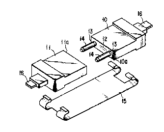
A conventional multicore optical connector has a
structure such as is shown in Fig. 1. Referring to
Fig. 1, numerals 10 and 11 denote multicore optical con-
nectors. End faces l0a and lla of the multicore optical
connectors 10 and 11 have a pair of alignment pin holes
13 and optical fiber holes 12 formed therebetween.
Optical fibers of a multicore optical fiber tape 16 are
inserted in the optical fiber holes 12 so that the end'
faces thereof are exposed. A pair of alignment pins 14
are inserted in the alignment pin holes 13 of the multi-
core optical connectors 10 and 11. More specifically,
one end portion of the pair of alignment pins is
inserted in the alignment pin holes 13 of the connector
10, and the other end portion is inserted in the align-
ment pin holes 13 of the connector 11. In this manner,
the connection end faces 10a and 11a of the connectors
10 and 11 are brought into contact with each other.
Thereafter, the connectors 10 and 11 are held together
by an elastic clip 15.
As described above, the conventional multicore
optical connector has a plurality of optical fiber holes
arranged in a row and interposed between a pair of
alignment pin holes 13. With this structure, only two
to nineteen optical fibers can be connected at a time

2U~~~~~
- 2 -
by using conventional multicore optical connectors.
In recent years, with the expansion of optical com-
munication networks to transmit a greater amount of
information, demand has arisen for a more compact
optical connector for connecting a greater number of
optical fibers than is possible using conventional
optical connectors.
If the pitch of the optical fiber holes is reduced
to increase the number of optical fiber holes, it
becomes difficult to determine which optical fiber
should be inserted in which optical fiber hole. As a
result, the efficiency with which multicore optical con-
nectors are manufactured is greatly reduced.
Further, the number of optical fibers contained in
one multicore optical fiber tape cannot be changed.
Therefore, to manufacture a multicore optical connector
for connecting a greater number of optical fibers, it is
necessary to use a plurality of multicore optical fiber
tapes. Thus, if the optical fiber holes are arranged at
regular pitches, the side end portions of adjacent
optical fiber tapes will overlap each other when optical
fibers are inserted in the optical fiber holes. As a
result, optical fibers near the end portion of an
optical fiber tape may be bent. This bent or the like
is undesirable since it may cause the increase of con-
nection loss.
An object of the present invention is to provide

- 3 -
a compact multicore optical connector which can connect
a greater number of optical fibers than a conventional
optical connector, while reducing the possibility of
connection loss.
The object cari be attained by a multicore optical
connector including a connector body having a pair of
alignment pin holes and a plurality of optical fiber
holes formed therebetween and optical fibers inserted in
the optical fiber holes such that the end faces of the
optical fibers are exposed through the optical fiber
holes, wherein the optical fiber holes are divided into
optical fiber hole groups the number of which coincides
with the number of groups of optical fibers, and the
optical fiber hole groups are separated from one
another.
This invention can be more fully understood from
the following detailed description when taken in con-
junction with the accompanying drawings, in which:
Fig. 1 is a perspective view showing a conventional
multicore optical connector;
Fig. 2 is a diagram showing a multicore optical
connector according to an embodiment of the present
invention;
Fig. 3 is a plan view of the multicore optical con-
vector shown in Fig. 2;
Fig. 4 is a cross-sectional view of the multicore
optical connector taken along the line A-A in Fig. 3;

20~~~~
and
Fig. 5 is a diagram showing a multicore optical
connector according to another embodiment of the present
invention.
Embodiments of the multicore optical connector of
the present invention will now be described, with
reference to the accompanying drawings.
Figs. 2 to 4 show an embodiment of the present
invention. The connection end face of the multicore
optical connector 20 has a pair of alignment pin holes
21. Optical fiber holes 22 are formed between the
alignment pin holes 21. The optical fiber holes 22 are
divided into a plurality of optical fiber hole groups
23, each constituted by a plurality of optical fiber
holes arranged at a pitch of about 180 to 250 Vim. It is
desirable that the distance D between the optical fiber
hole groups should be 300 to 1500 um. If the distance D
is smaller than 300 um, distance D is indistinguishable
from the pitch of optical fiber hole, and if it is
greater than 1500 um, the size of the optical connector
is to be large.
Although the number of the optical fiber holes 22
constituting one optical fiber hole group 23 is set to
16 in the embodiment shown in Fig. 2, it can be changed
in accordance with the number of optical fibers con-
tained in an optical fiber tape. Tt is desirable that
the number of the optical fiber holes 22 should coincide

20~~~~
with the number of the optical fibers included in the
optical fiber tape.
Although the number of the optical fiber hole
groups 23 is three in the embodiment shown in Fig. 2, it
may be two or more than three so that number of the
optical fiber hole groups matchs the number of the
optical fiber tape.
As shown in Figs. 3 and 4, an opening 25 is formed
in the central portion of a main surface 24 of the
multicore optical connector 20 so as to reach to the
optical fiber holes 22. Guide portions 26, on which
optical fiber tapes are placed, are formed at the bottom
of the opening 25 and partitioned by partitioning
portions 27. The number of the guide portions 26 coin-
tides with the number of the optical fiber hole groups
23 (e. g., three, in this embodiment). Optical fiber
tape inserting holes 28 are formed in the end face on
the opposite side of the multicore optical connector
from the connection end face. The optical fiber tape
inserting holes 28 communicate with the opening 25. The
partitioning portions 27 reaches the end face of the
optical connector 20 having the optical fiber tape
inserting holes 28. Thus, the mechanical strength of
the optical connector 20 is improved, thereby preventing
the optical connector from cracking. The cross section
of the partitioning portions 27 may be semicircular as
shown in Fig. 4, or rectangular.

2~'~'~~55
- 6 -
When optical fibers are to be loaded in the above-
described multicore optical connector, for example,
three 16-core optical fiber tapes and boots are inserted
through the optical fiber tape inserting holes 28. The
optical fiber tapes are guided by the guide portions 26
and the optical fibers are inserted in the corresponding
optical fiber holes 22. At this time, the optical fiber
tapes do not overlap or interrupt each other by virtue
of the partitioning portions 27. Since the opening 25
is formed in the multicore optical connector, the
optical fiber tapes can be inserted very easily.
Further, since the optical fiber holes 22 are divided
into three optical fiber hole groups 23, the optical
fibers can be inserted to the corresponding optical
fiber holes without failure. Moreover, since the
optical fiber hole groups 23 are separated at the
distance D from one another, the optical fiber tapes do
not overlap when inserted. As a result, the optical
fibers are prevented from being bent, thereby reducing
the connection loss.
Fig. 5 shows another embodiment of the multicore
optical connector according to the present invention. A
multicore optical connector 20 has a pair of alignment
pin holes 2l and six optical fiber hole groups 23
arranged in two rows and three columns between the
alignment pin holes 21, each group consisting of 8
optical fiber holes 22. With this arrangement, a more

2~~~~5~
highly integrated multicore optical connector can be
obtained.
As has been described above, the multicore optical
connector of the present invention is more compact and
capable of connecting a greater number of optical fibers
with less connection loss as compared to a conventional
connector. Thus, it is well suited for application to
an optical communication network for transmitting a
large amount of information.

Representative Drawing
A single figure which represents the drawing illustrating the invention.
Administrative Status

2024-08-01:As part of the Next Generation Patents (NGP) transition, the Canadian Patents Database (CPD) now contains a more detailed Event History, which replicates the Event Log of our new back-office solution.

Please note that "Inactive:" events refers to events no longer in use in our new back-office solution.

For a clearer understanding of the status of the application/patent presented on this page, the site Disclaimer , as well as the definitions for Patent , Event History , Maintenance Fee  and Payment History  should be consulted.

Event History

Description Date
Inactive: IPC from MCD 2006-03-11
Time Limit for Reversal Expired 2005-09-02
Letter Sent 2004-09-02
Grant by Issuance 1999-08-24
Inactive: Cover page published 1999-08-23
Inactive: Final fee received 1999-05-11
Inactive: Correspondence - Formalities 1999-05-11
Pre-grant 1999-05-11
Notice of Allowance is Issued 1998-11-18
Letter Sent 1998-11-18
Notice of Allowance is Issued 1998-11-18
Inactive: Status info is complete as of Log entry date 1998-11-03
Inactive: Application prosecuted on TS as of Log entry date 1998-11-03
Inactive: Approved for allowance (AFA) 1998-10-14
Application Published (Open to Public Inspection) 1993-03-05
Request for Examination Requirements Determined Compliant 1992-09-02
All Requirements for Examination Determined Compliant 1992-09-02

Abandonment History

There is no abandonment history.

Maintenance Fee

The last payment was received on 1998-08-11

Note : If the full payment has not been received on or before the date indicated, a further fee may be required which may be one of the following

  • the reinstatement fee;
  • the late payment fee; or
  • additional fee to reverse deemed expiry.

Please refer to the CIPO Patent Fees web page to see all current fee amounts.

Fee History

Fee Type Anniversary Year Due Date Paid Date
MF (application, 5th anniv.) - standard 05 1997-09-02 1997-08-06
MF (application, 6th anniv.) - standard 06 1998-09-02 1998-08-11
Final fee - standard 1999-05-11
MF (patent, 7th anniv.) - standard 1999-09-02 1999-08-09
MF (patent, 8th anniv.) - standard 2000-09-04 2000-08-16
MF (patent, 9th anniv.) - standard 2001-09-03 2001-08-17
MF (patent, 10th anniv.) - standard 2002-09-03 2002-08-16
MF (patent, 11th anniv.) - standard 2003-09-02 2003-08-21
Owners on Record

Note: Records showing the ownership history in alphabetical order.

Current Owners on Record
NIPPON TELEGRAPH & TELEPHONE CORPORATION
THE FURUKAWA ELECTRIC CO., LTD.
Past Owners on Record
HIROYUKI YAMADA
JUN YAMAKAWA
MASAMI SAITO
MICHITO MATSUMOTO
TADASHI HAIBARA
TOSHIHIKO OOTA
Past Owners that do not appear in the "Owners on Record" listing will appear in other documentation within the application.
Documents

To view selected files, please enter reCAPTCHA code :


To view images, click a link in the Document Description column. To download the documents, select one or more checkboxes in the first column and then click the "Download Selected in PDF format (Zip Archive)" or the "Download Selected as Single PDF" button.

List of published and non-published patent-specific documents on the CPD .

If you have any difficulty accessing content, you can call the Client Service Centre at 1-866-997-1936 or send them an e-mail at CIPO Client Service Centre.


Document
Description 
Date
(yyyy-mm-dd) 
Number of pages   Size of Image (KB) 
Abstract 1994-03-31 1 15
Cover Page 1994-03-31 1 18
Drawings 1994-03-31 2 44
Description 1994-03-31 7 204
Claims 1994-03-31 1 33
Claims 1998-09-16 1 30
Cover Page 1999-08-17 1 35
Representative drawing 1999-08-17 1 9
Commissioner's Notice - Application Found Allowable 1998-11-18 1 164
Maintenance Fee Notice 2004-10-28 1 173
Correspondence 1999-05-11 1 34
Fees 1998-08-11 1 39
Fees 1997-08-06 1 35
Fees 1999-08-09 1 28
Fees 1996-08-07 1 33
Fees 1995-08-21 1 38
Fees 1994-08-19 1 37
Courtesy - Office Letter 1993-04-02 1 74
Prosecution correspondence 1998-08-19 1 32
Prosecution correspondence 1998-01-07 4 123
Examiner Requisition 1997-07-08 2 100
Examiner Requisition 1998-02-20 2 71