Note: Descriptions are shown in the official language in which they were submitted.
CA 02077362 2004-02-04
TELECOMMUNICATIONS SERVICE ENTRY INSTALLATION
Field Of The Invention
The present invention relates to telecommunications equipment
and in particular to a telecommunications service entry installation.
Background Of The Invention
Service entry installations in telecommunications systems to
connect external telecommunications lines to internal telecommunications
equipment are well known in the art. These installations are used to protect
telecommunications equipment from overloads that may occur on the external
telecommunications cables due to lightening strikes or other electrical
faults.
Conventional installations have included a single housing divided into a
number of isolated compartments. Usually the rear compartment of the
housing defines the splice chamber in which the individual lines of the
external telecommunications cable are separated. The front of the splice
chamber is often in the form of a door which constitutes the back of a
connection chamber. The separated conductors from the external
telecommunications cable are connected to a multiconductor fuse assembly
within the splice chamber before being passed through the door and
electrically connected to a connector panel. The connector panel also has
internal conductors connected to it which extend to telecommunications
equipment. Fuses are plugged into the sockets of the connector panel to
connect electrically the internal conductors to the external conductors and to
provide additional protection to the telecommunications equipment.
Although these installations function satisfactorily, problems
exist in that if an overload occurs on the external telecommunications cable
and the fuse assembly in the splice chamber blows, the entire installation
must be discarded and replaced even though sections of it may have been
uninjured during the overload. This occurs because the splice chamber and
the connection chamber are located in the same housing and are only
separated by dividing walls. Accordingly, there is a need for an improved
telecommunications service entry installation.
CA 02077362 2004-09-30
-2-
It is therefore an object of the present invention to obviate or
mitigate at least some of the disadvantages associated with prior art
telecommunications service entry installations.
Summary Of The Invention
According to one aspect of the present invention there is
provided a telecommunications service entry installation comprising:
a junction box for receiving a multiconductor cable;
a distribution box for receiving conductors from
telecommunications equipment, said junction box and distribution box being
positioned side by side; and
releasable electrical connection means to connect electrically
said junction box and said distribution box and thereby connect conductors of
said cable to conductors of said telecommunications equipment, said
releasable electrical connection means including mating male and female
connectors, one of said male and female connectors being on said junction
box and the other of said male and female connectors being on said
distribution box, said junction box including fuse means therein to isolate
conductors of said cable from conductors of said telecommunications
equipment in the event of a fuse condition and confine said fuse condition to
said junction box, said junction box and said distribution box being
releasably
mounted on a back plate, one said of said junction box and distribution box
being slidable laterally relative to the other of said junction box and
distribution
box to bring said male and female connectors into and out of mating
engagement.
CA 02077362 2004-09-30
-3-
Preferably, the releasable connection means is in the form of
mating male and female multi-pin connectors with one of the connectors being
on each of the boxes. It is also preferred that each of the boxes is
releasably
mounted on a back plate with at least one of the boxes being slidable
laterally
with respect to the other of the boxes to bring the male and female connectors
into and out of mating engagement.
Preferably, the junction box has a Bix~ block in it which receives
the conductors from the cable on one set of its terminals. Fusible links
extend
between the other set of the Bix~ block's terminals and the connector on the
box to constitute the fuse means. It is also preferred that the distribution
box
houses a protector panel which allows selective ones of the conductors
extending from telecommunications equipment to be electrically connected to
the connector box.
According to another aspect of the present invention there is
provided a telecommunications service entry installation comprising:
a junction box for receiving a multiconductor cable;
a distribution box for receiving conductors from
telecommunications equipment; and
releasable electrical connection means to connect electrically
said junction box and distribution box and thereby connect electrically
conductors of said cable to the conductors from said telecommunications
equipment, said releasable electrical connection means including mating
connectors, one of said mating connectors being on said junction box and the
other of said mating connectors being on said distribution box, said junction
box housing fuse means to isolate conductors of said cable from said
telecommunications equipment in the event of a fuse condition and confine
said fuse condition to said junction box, said junction box and said
distribution
box being releasably mounted on a back plate, one of said junction box and
said distribution box being slidable laterally relative to the other of said
junction
box and distribution box to bring said mating connectors into and out of
mating
engagement.
CA 02077362 2004-09-30
-4-
According to yet another aspect of the present invention there is
provided a telecommunications service entry installation comprising:
a junction box for receiving a multiconductor cable;
a distribution box for receiving conductors from
telecommunications equipment; and
releasable electrical connection means to connect electrically
said junction box distribution box and thereby connect electrically conductors
of said cable to the conductors from said telecommunications equipment, said
releasable electrical connection means including mating connectors, one of
said connectors being on said junction box and the other of said connectors
being on said distribution box, said junction box housing fuse means to
isolate
conductors of said cable from said telecommunications equipment in the event
of a fuse condition and confine said fuse condition to said junction box,
wherein said distribution box houses a protector panel, said protector panel
having terminals with some of the terminals being electrically connected to
the
connector on said distribution box and the remainder of the terminals being
connected to one set of terminals of second connection means, a second set
of terminals of said second connection means being in electrical
communication with said one set of terminals and receiving conductors from
said telecommunications equipment, said protector panel allowing selected
ones of said conductors from said telecommunications equipment to be
electrically connected to the mating connector on said distribution box.
According to still yet another aspect of the present invention
there is provided a telecommunications service entry installation comprising:
a junction box for receiving a multiconductor cable;
a distribution box for receiving conductors from
telecommunications equipment, said junction box and distribution box being
positioned adjacent one another; and
releasable connectors on said junction and distribution boxes to
connect electrically said junction box and said distribution box and thereby
connect conductors of said cable to conductors of said telecommunications
CA 02077362 2004-09-30
-5-
equipment, said junction box including fuse means therein to isolate
conductors of said cable from conductors of said telecommunications
equipment in the event of a fuse condition and confine said fuse condition to
said junction box, the interior of said junction box being accessible when
said
junction and distribution boxes are electrically connected.
According to still yet another aspect of the present invention
there is provided a telecommunications service entry installation comprising:
a junction box for receiving a multiconductor cable;
a distribution box for receiving conductors from
telecommunications equipment, said junction box and distribution box being
positioned side by side; and
releasable connectors on adjacent sides of said junction and
distribution boxes to connect electrically said junction box and said
distribution
box and thereby connect conductors of said cable to conductors of said
telecommunications equipment, said junction box including fuse means
therein to isolate conductors of said cable from conductors of said
telecommunications equipment in the event of a fuse condition and confine
said fuse condition to said junction box, said junction box and said
distribution
box being releasably mounted on a back plate, one of said junction box and
distribution box being slidable laterally relative to the other.
The present invention provides advantages in that in the event
of an overload on the multiconductor cable, the fusible links vaporize to
isolate
the telecommunications equipment from the cable, while confining the fuse
condition to the junction box. This maintains the remainder of the
installation
in working order. Also, since the junction box and the distribution box are
easily separable, replacement of the junction box after the occurrence of a
fuse condition is facilitated. Thus, in the event of such a fuse condition,
only
the junction box needs to be replaced.
CA 02077362 2004-02-04
-6-
Brief Description Of The Drawings
An embodiment of the present invention will now be described
more fully with reference to the accompanying drawings in which:
Figure 1 is a perspective view of a telecommunications service
entry installation in accordance with the present invention;
Figure 2 is a perspective view of the telecommunications service
entry installation illustrated in Figure 1 with individual boxes of the
telecommunications service entry installation exposed;
Figure 3 is an enlarged, rear view of a portion of one of the
boxes illustrated in Figure 2;
Figure 4a is an enlarged, front view of the box of Figure 3 in an
engaged condition;
Figure 4b is an enlarged front view of the box of Figure 3 in a
disengaged condition;
Figure 5 is a perspective view taken from the rear of the interior
of the other box illustrated in Figure 2; and
Figure 6 is an exploded perspective view of the
telecommunications service entry installation illustrated in Figure 1.
Detailed Descriation Of The Preferred Embodiment
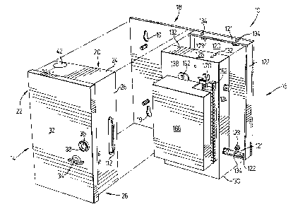
Referring to Figures 1, 2 and 6, a telecommunications service
entry installation is shown and is generally identified by reference numeral
10.
The telecommunications service entry installation includes a multiconductor
cable 12 passing through a junction box 14 usually referred to in the
telecommunications industry as a service entry panel. A protector or
distribution box 16 (hereinafter referred to as "distribution box") is located
beside the junction box 14 and is electrically connected to it as will be
described. The two boxes 14 and 16 are mounted on a back plate 18 which
itself can be mounted on a wall or other suitable support surface via
fasteners
(not shown) passing through slots 19 in the back plate 18.
The junction box 14 is similar to that disclosed in U.S. Patent
No. 5,023,397 to Tomes et al and assigned to Circa Telecommunications Inc.,
CA 02077362 2004-02-04
-7-
assignee of the present application. The junction box 14 includes a rear panel
20 and peripheral side walls 22, 24, 26 and 28. An inturned lip 30 is formed
along the front edge of each side wall. A flange 31 is also formed on the side
wall 26 below the lip 30 (see Figure 4a). A door 32 is hinged to the side wall
22 near its front edge so as to be spaced from the rear panel 20. The door 32
has a lock 34 on it which when turned with the door closed moves between the
space defined between the lip 30 and the flange 31. A bolt 36 surrounded by a
circular cup 38 is on the door 32 and is engageable with a threaded aperture
40 formed in the lip 30 on the side wall 26. The bolt 36 is accessible only
with
a specialized tool and is used to prevent unauthorized access to the junction
box 14. To permit passage of the cable 12 into the junction box 14, each of
the side walls 24 and 28 is provided with an aperture 42. The cable 12 is
protected within the apertures 42 by grommets 44.
Each of the side walls 24 and 28 is made in two portions
indicated by reference numerals 24a, 28a, 24b and 28b respectively. The
portions 24a, 28a of side walls 24 and 28 are secured to the side wall 22
whereas the portions 24b and 28b of side walls 24 and 28 are secured to the
side wall 28. The portions of each side wall meet along the centre line of the
aperture 42 so that the junction box 14 may be removed from around the cable
12 without disturbing it. The side wall 22 is secured to the rear panel 20 by
a
flange 50 integrally formed with the side wall. Upstanding studs 52 on the
rear
panel 20 pass through slots 54 formed in the flange 50 and receive nuts 56 to
secure the side wall 22 to the rear panel 20. Upstanding studs 58 are also
provided on both portions of the side walls 24 and 28. The studs 58 pass
through apertures formed in flanges 62 bridging the junction between the side
wall portions. Nuts 64 engage the studs 58 to secure the side wall portions
together.
The rear panel 20 has elongate slots 22a formed in it through
which threaded studs 22b extending from the back plate 18 pass. Nuts 22c
engage the studs 22b to secure the junction box 14 to the back plate 18.
When the nuts 22c are loosened, the junction box 14 is laterally slidable away
from the distribution box 16 (see Figure 4b).
CA 02077362 2004-02-04
-$-
Within the junction box 14 is located a Bix~ block 70 mounted
on a rectangular support structure 72 (see Figure 3). The support structure
72 includes a top panel 74 and side walls 76, 78 80 and 82 about the
periphery of the top panel 74. The rear edges of the side panels rest on the
rear panel 20 to space the Bix~ block 70 from the rear panel 20. Flanges 84
extend outwardly from the rear edge of the side walls 76 and 80 at spaced
locations and receive threaded studs 86 upstanding from the rear panel 20.
Nuts 88 engage the studs 86 to secure the support structure 72 within the
junction box 14.
A pair of flanges 90 are also provided on side walls 76 and 80
near the top panel 74 and are generally in the same plane as the top panel.
The flanges 90 have threaded apertures 92 formed in them. A cover 94
overlies the support structure 72 to cover the Bix~ block 70 and includes
flanges 96 which overlie flanges 90 when the cover 94 is in place. Screws 98
pass through apertures 100 in the flanges 96 and engage the threaded
apertures 92 to secure the cover 94 on the support structure 72.
The cover 94 has a portion of one of its side walls removed (not
shown) to permit conductors 103 extending from the cable 12 to pass. The
conductors are punched into the upper row of terminals 70a of the Bix~ block
70. Similarly, the side wall 76 of the structure 72 adjacent side panel 26 has
an aperture (not shown) formed in it so that fusible conductors 106 punched
into the bottom row of terminals 70b of the Bix~ block 70 can pass. The
fusible conductors 106 are bundled and held by straps 108 and terminate at a
multi-pin, male connector 112 mounted on side wall 26 of the junction box 14.
The gauge of the fusible conductors 106 is selected based on the type of
service supplying the telecommunications service entry installation 10.
The distribution box 16 includes a rear panel 120 having an
upturned lip 122 formed about its periphery. The rear panel 120 has
apertures in it which receive upstanding threaded studs 121 on the back plate
18. Nuts 123 engage the studs 121 to secure the rear panel 120 to the back
plate 18. Side walls 124 to 130 of the distribution box 16 pass over the
upturned lip 122 and abut against the back plate 18. Side walls 126 and 130
CA 02077362 2004-02-04
_g_
have apertures 132 formed through them which align with threaded apertures
134 in the upturned lip 122. Screws 136 pass through the apertures 132 and
engage the apertures 134 in the lip 122 to secure the side walls to the rear
panel 120. A top panel 138 is integrally formed with the front edge of the
side
walls and has a centrally located aperture formed in it.
Within the aperture is located a protector panel 140 such as that
disclosed in U.S. Patent No. 5,044,962 to Tomes et al and assigned to the
present assignee. The protector panel 140 is mounted within the distribution
box 16 so that the front face 142 of the panel 140 is flush with the planar
surface of the top panel 138. The protector panel 140 includes a mounting
panel 144 and a rear face plate 146 removably secured to the back face of
the mounting panel. The mounting panel 144 and the face plate 146 are
formed of insulating, moulded plastic. An array of sockets 148 is formed
through the mounting panel 144.
Within the sockets 148 are located terminal contacts 154. The
rear end of some of the terminal contacts 154 pass through apertures formed
in the rear face plate 146. The rear end of the other terminal contacts 154
terminate in grooves 156 formed in the back face of mounting panel 144 and
are covered by the face plate 146. Ground conductors (not shown) extend
along the grooves 156 and are soldered at one end to a bus bar 160 running
along one side of the mounting panel 140. A ground conductor 162 extends
from the bus bar 160 and is connected to an external ground connector 164
provided on side wall 124. A second ground connector 166 is also provided
on the side wall and is electrically connected to ground connector 164 by a
shielded conductor 168 within the distribution box 16.
A Bix~ block 170 running alongside the protector panel 140 is
mounted on the distribution box 16 by screws 172 passing through the side
walls. The bottom row of terminals 170k of the Bix~ block 170 is within the
distribution box 16 and has conductors 174 extending from some of the
individual terminal contacts 154 punched into its terminals. The other
terminal
contacts 154 receive conductors 176 extending from a female connector 178
on side wall 128. The female connector 178 mates with male connector 112
CA 02077362 2004-02-04
-10-
on side wall 26 to connect electrically the two boxes 14 and 16 respectively.
The top row of terminals 170b of the Bix~ block 170 has
conductors 180 extending to telecommunications equipment (not shown)
located at the telecommunications service entry installation 10 punched into
its terminals. A conductor guide 182 runs along side the Bix~ block 170 to
hold the conductors 180 punched into the Bix~ block 170 in place. A cover
186 is hingedly mounted on a flange 188 secured to the top panel 138 to
cover the protector panel 140 and the Bix~ block 170. The cover has a flange
190 on it which allows a screw 192 to pass and engage with a threaded
aperture 194 in the top panel. This allows the cover 190 to be secured in a
closed condition (see Figure 1 ). A portion of the cover side wall is removed
over the guide 182 so as not to interface with the conductors 180. When the
cover 190 is in the open condition as seen in Figure 2, plug-in type protector
assemblies 200 can be inserted into the sockets to connect electrically the
conductors 180 to the conductors of the cable 12 when the female and male
connectors 112 and 178 respectively are in mating engagement.
In use, when plug-in protector assemblies 200 are received in
the sockets 148 of the protector panel 140, the conductors 174 extending
between the terminal contacts 154 and the Bix~ block 170 and the conductors
176 extending between the terminal contacts 154 and the female connector
178 are electrically connected. When the male connector 112 is in mating
engagement with the female connector, the telecommunications equipment is
electrically connected to the conductors of the cable 12.
If an overload occurs on the cable 12, it is passed to the fusible
conductors 106 via the conductors 103 of the cable and the Bix~ block 70.
When the overload exceeds the rating of the fusible conductors 106, the
fusible conductors 106 vaporize thereby electrically isolating the junction
box
14 from the distribution box 16. This ensures that the fuse condition is
confined to the junction box 14. If this occurs, with the present design
replacement of the junction box 14 is readily achievable and this is done by
removing the nuts 22c from studs 22b and sliding the junction box 14 laterally
away from the distribution box 16. This releases the male and female
CA 02077362 2004-02-04
-11-
connectors 112 and 178 and thus, physically isolates the two boxes. The nuts
64 holding the flanges 62 to the side walls are then removed from the studs
58 and the conductors of the cable 12 are pulled from the Bix~ block 70. The
nuts 56 fastening the flange 50 to the rear panel 20 are also removed from the
upstanding studs 52. Once this is done, the junction box 14 can be removed
from the back plate 18 and from around the cable 12 without disturbing the
cable.
Replacement of the junction box 14 is achieved in the reverse
order by connecting the side wall portions together via the flanges 62 to
surround the cable 12 and by securing the flange 50 to the rear panel 20. The
junction box 14 is then placed on the back plate 18 with the studs 22b passing
through the slots 22a. The nuts 22c can then be engaged with the studs but
the junction box 14 must be moved towards the distribution box 16 to mate
the connectors 112 and 178 before the nuts 22c are tightened.
If the overload is not sufficient to vaporize the fusible conductors
106, but is significant, the plug-in protector assemblies 200 will act as
fuses to
isolate the telecommunications equipment from the conductors of the cable
12.
The present invention provides advantages in that if an overload
occurs on the incoming cable 12 and the fusible conductors 106 vaporize, the
fuse condition is confined to the junction box 14 which can be easily removed
from the remainder of the telecommunications service entry installation 10
without requiring rewiring of the remaining installation and without
disturbing
the incoming cable. This overcomes the drawbacks associated with
conventional telecommunications service entry installations wherein the entire
installation must be replaced if a fuse condition occurs.