Note: Descriptions are shown in the official language in which they were submitted.
2077~
This invention relates to a new system of modulable walls,
especially designed to take various shapes for the creation of
personalized spaces in so-called ~Landscape offices".
Many systems of this kind are known but they have various
drawbacks: lack of charm and of aesthetic, despite their high cost,
lack of stability, lack of attraction, being cold and stiff.
The invention obviates all these drawbacks, thanks to a new
l O artlcte, simple, cheap and of pleasant use. :
To thls effect the invention provides a modulable wall system for
professional use comprising. in a known manner, panels hinged
ones with the others around flexible vertical areas, with as a new
feature, the fact that each individual panel consists in a flat core
made of a light material, peripherally limited by a rigid area provided
for catching frame elements having along their vertical sides means
for linking and hinging with the next panels and resting means along
their lower horizontal side.
Several modifications of this invention can be carried out with
2 O thelr various specific advantages~ -
According to a first modification the flat core consists in two plates
of an expanded synthetlc material, e.g~ polyurethane, said two plates
b~ing assembled back to back and covered by a thin flexlble sheet
of spon~y materlal wlth a decorative surface, said frame elements
2 5 balng under the form of sectlons hooked into longitudinal grooves in ~; ;
aach fac~ af the core rigld area, parallel to each edge.
2 ~77~
Such a flat core can be built along a known process such as described in
US-A-3,345,439 and US-A-3,493,449. In said known so-ca~led over-casting
process, the peripheral areas of the panel are over-densified, less porous and
therefore more rigid than the remaining portion of the core, which allows on tha5 one hand to assemble back to back the two plates forming the panel, and on
the other hand to provide said panel with moulded grooves strong enough to
receive the sections forming the frame, hooked thereto.
According a second modification which is simpler and cheaper, the flat core
consists in a plate made of agglomerated fibers on which is downwardly
10 slipped a cover element made of a spongy thin and flexible sheet and
provided with a surface decoration, said cover element slipped down on said
core over an additional frame made of plastic sections comprising grooves in
which the main frame elements are hooked, which maintain therefore the
cover by pinching.
Both modiflcations comprise additional common features: one of said
common features is the provision of angle elements joining the frame
elements. Said angle element is a moulded piece comprising studs at right
angles each others designed to be inserted into the respective ends of said
sectlons. The lower angle elements comprise thereads for screwing adjustable
2 0 feet for the panel.
Another common feature is the provision of a central groove in said main
frame sections, said groove being designed to receive either a vertical flexiblejoining band or an horizontal rib of a stabilizing base for one panel or for thecomplete wall.
2 5 In the second modification, it is provided means for fixing the lower edges of
Ihe cover, said means consisting in a stem forced together with said edges into
a ~roove of the corresponding additional frame plastic segment.
The main frame sections and the angle elements can be made of metal or
of pla~tic.
The Invention will now be described in detail with reference to the attached
drawln~j~, on whlch:
Fl~llr0 1 Is a front view of an example of the first modification of the
Inv3ntlon wlth two back to back plates of expanded polyurethane, forming an
Indivldual panel.
~5 Fl~ura 2 Is a partial horizontal section along ll-ll of figure 1.
.~ . . . ...
3 2~774~
Figure 3 is a partial vertical section along lll-lll oF figure ~.
Figure 4 is a partial vertical section along IV-IV of figure 1.
Figure 5 is a partial horizontal section of the assembly of two panels as
shown on figure 1-4.
Figure 6 is a front view of an example of the second modification of the
invention with a panel of agglomerated fibers and a frame made of PVC
sections.
Figure 7, 8,9 and 10 are similar to figure 2, 3, 4 and 5 for the panel of figure6.
1 0 Figure 11 is a perspective view of an angle element usPd in the main frame
of a panel according to the invention.
Figure 12 shows a base for the panels of the invention and,
Figure 13 is a vertical section of the lower part of a panel of the invention,
resting upon a base as shown on figure 12 and upon a screwed foot.
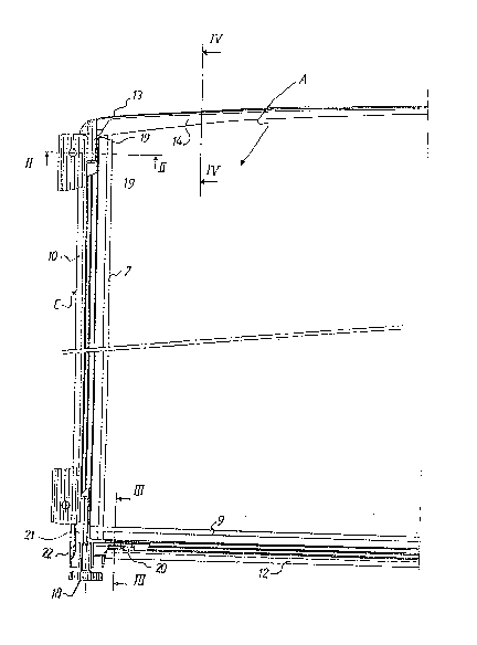
~i 5 Referring first to figures 1 to 5, it is shown a panel according to the first
modiflcation of the invention, comprising a central portion or core A and a
peripheral frame C.
In this modification, the core A comprises two flat plates 1, 2, each made by
overcasting expanded polyurethane upon a back made of a spongy flexible
sheet 3, 4 covered with a decorative fabric 5, 6, both plates 1, 2 being
assembled back to back by sticking, pinching or any similar way such as both
visible faces of the case A show the decorative fabric 5, 6.
Parallel to each vertical edge of the panel, each extarnal face of the plates
1, 2 is provided with a groove 7, 8, and parallel to the lower horizontal edge of
2 5 the panel, the external face of the plates 1, 2 is provided with a groov~ 9, said
grooves 7, 8, 9 being at a short distance of the edges, e.g. 2-4 cm and being
formed when the core is overcast upon the back.
As shown on figures 2 and 3, said grooves 7, 8, 9 are used for hooking,
upon the corresponding edges of the core, of the three elements I0, 11, 12 or
the frame C, which consist in sections, e.g. of aluminium. Along the fourth edgeof tho core, I. e. the upper edge, which is siightly convex,.the fourth section 13
of the frame is a U section of plastic, pinching to side grooves 14 of the plates
1, 2 edges (Flgure 4).
Each vertlcal section 10, 11 is of U shape, tha branchss thereof are
elastically hooked or slipped in the grooves 7, 8, and the base thereof is
, . . . . .. - .. . . . . . . ~ . .
.. . . . . .. . ... . . . . . .. . ... . . .. . .. .. .
.. , ., ~ .. . ~ -, .- . , - , .. : .. . . . ...
4 ~7~
shaped as a longitudinal groove 15 in which is inserted an edge of a flexible
band 16 used as an hinge between two successive panels (Fig.5).
The lower horizontal section 12 has also a U shape with a groove 15, at
each end thereof is screwed a thereaded foot 18 (Fi~. 3).
It is clear that, due to this structure of the panel, lhe frame C is at ~ level with
the faces of the core 1, 2.
It is also understood that the process so-called overcasting used for making
the core A is already known and used for making articles in other technical
fields, e.g. pieces for the car industry. However this process had never been
used for making framed cores as in this invention.
The plates 1, 2 are of expanded material, and consequently very light, but
in this overcasting process the superficial portions and the edges, comprising
the grooves 7, 8, 9, are "over-densified", or less porous, and more strong,
which allows the hooking of the sections 7, 8, 9.
Finally, as shown on figure 1, the ends of the upper section ~3 comprise
vertical studs ~9, integral with the section, and which are inserted into the
vertlcal sections ends 10, 11; said vertical sections 10, 11 are joined at theirlower ends with the lower horizontal section 12 by angle elements 22 (figure
11) comprlsing horizontal studs 20 and vertical studs 21 forced into the
2 0 sectlons ends and used as braces.
Sald braces are vertically threaded to accomodate the screwed feet 18.
Figure 11 shows such a brace, in perspective with its stud, the screwed foot 18
being in place. Said brace 22 is blocked into the vertical section 10 with a
vertical screw 17 (figure 3).
Referring now to figure 6 to 10, it is shown a second modification of the
Inv~nllon, wlth the same numerals for the corresponding elements.
The panel of the invention still comprises a core A and a frame C, but the
structure of the core A is different.
In thls modification, said core ~ is made of an unique plate of agglomerated
3 ~ partlcles 23, such as wood fibers agglomerated by a synthetic resin, e.g. PVC;
u,~on this plate in slipped downwardly a cover or sheath 24 made of a flexible
~pon~y or porous sheet with a decorative surface.
Th~ frame C is similar to the frame of the first modification. However, the
plat~ ~3 does nat comprise grooves such as 7, 8, 9, so that, with a view to hook~5 i~alci frame C to the core A, the plate 23 must be provided, before slipping of
:, - " . ~ , " , - ,,
, , ... . ,, :,,, . ...... . , , . ~. ..
:, . . ; : ~ -
5 ~077~0~
the sheath 24, with an additional frame made of plastic sections 25, e.g. of
PVC, having a shape of two U joined along their bases, tha branches 26 of the
~irst U pinching the edge of the plate 23 and the branches 27 of the second U
being closer and having external rims 28 and internal rims 33, forming in the
external surface of the second U two channels 29 adapted to receive the
branches of the sections 10, 11, 12 of the main frame C, which are therefore
hooked to the plate 23 and which maintain the sheath 24 into said channel 29.
Considering that the cover 24 is a bag closed at its upper end and slipped
downwardly on the plate 23, both faces of said cover are joined by a
1 0 continuous portion 30 along the vertical edges (figure 7), and by a continuous
portion 30 along the upper horizontal edge (figure 9). However the two lower
edges 34 of said bag are free. To fix the same it is provided means to force
said edges 34 into the base of the external U 27. Said means comprise a stem
31 having two grooves 32 which receive th~ internal rims 33 of the branches of
1 5 the U 27 (figure 8). Said stem 31 pushes and blocks therefore the edges of the
bag 24 into the bottom of the U 27~
As shown on figure 10, similar to figure 5, two successive panels P1, P2 are
Joined by a flexible band 40 inserted in the vertical graoves of the
corresponding vertical sections 10.
As shown by hatchings on figure 7-10, the angles of each panel frame
section are joined by braces the studs of which are forced into the sections `
ends, said braces being illustrated on figure 11. Said braces are also used for
screwing the feet 41.
Figures 12 and 13 show an example of a base provided to stabilize one or
2 5 several vertical panels, especially when said panels are individuals or in line.
Such a base comprises an substantially horizontal plate 41 made of heavy
material and having a vertical rib 42, the thickness of which is approximately
equal to the width of the external groove 43 of the section 44 forming the loweredge of a panel (figure 3 and 8). ~ `
3 0 The height H1, of said plate 41 with its rib 42 is higher than the height H2 of
a foot 18 when fully screwed into a brace ~2.
Referrin~ to figure 13, it can be seen than when said rib 42, is fully inserted
alon~ the proove 43, the plate 41 is positioned symetrically with respect, to the
panel. When the foot 18 is fully screwed in the brace 22 after passing through
a hole 45 in one end of plate 41 (figure 12), it is against the low0r face of said
- , . . . . . , , ..... - .- - ,.. ... ~.. . . .. .. .. ... - . - . - . . . . .
., .. . ~ .. , . . : .. . ;. .
6 ~7~
plate 41, so that the base is locked against the panel lower edge, said foot 18
being slightly above the ground. The plate 41 is therefore slightly inclined with
respect to the ground.
As shown on figure 13, such a base 41-42 is installed at one end only of a
5 panel, the other end resting on the ground by the foot 1~ screwed at the proper
level into the brace 22. It can be appreciated that the panel rests on the ground
by three points, i.e. both angles 46 of the plate 41 opposed to the hole 45, andthe screwed foot 18, allowing the adjustment of the height and slope of the
panel.
1 O Such a stabilizing base provides a proper rest for an erected panel alone.
However it should be appreciated that the panel of the invention is essentially
adapted to the erection of composite walls of any shape by associating a
number of panels along a sinuous path. In this case this base is only useful at
the ends of said path, the intermediate panels resting on the ground by their
15 respectiv~ feet 18 distributed along the overall twist of the path. In case said
path is too straight, it is advisable to add one or more intermediate stabilizing
basos,