Language selection

Search

Patent 2077865 Summary

Third-party information liability

Some of the information on this Web page has been provided by external sources. The Government of Canada is not responsible for the accuracy, reliability or currency of the information supplied by external sources. Users wishing to rely upon this information should consult directly with the source of the information. Content provided by external sources is not subject to official languages, privacy and accessibility requirements.

Claims and Abstract availability

Any discrepancies in the text and image of the Claims and Abstract are due to differing posting times. Text of the Claims and Abstract are posted:

  • At the time the application is open to public inspection;
  • At the time of issue of the patent (grant).
(12) Patent: (11) CA 2077865
(54) English Title: EQUALIZER FOR SLIDING TUBULAR MEMBERS
(54) French Title: EGALISATEUR DE MOUVEMENT POUR ELEMENTS TUBULAIRES
Status: Expired and beyond the Period of Reversal
Bibliographic Data
(51) International Patent Classification (IPC):
  • F16F 15/00 (2006.01)
  • B23Q 1/26 (2006.01)
  • B60P 3/32 (2006.01)
  • B60P 3/34 (2006.01)
  • B62D 21/14 (2006.01)
  • B62D 33/027 (2006.01)
  • B62D 33/063 (2006.01)
(72) Inventors :
  • DEWALD, JAMES E., JR. (United States of America)
  • MCMANUS, PATRICK W. (United States of America)
(73) Owners :
  • VT HOLDINGS II, INC.
(71) Applicants :
  • VT HOLDINGS II, INC. (United States of America)
(74) Agent: BORDEN LADNER GERVAIS LLP
(74) Associate agent:
(45) Issued: 2002-07-02
(22) Filed Date: 1992-09-09
(41) Open to Public Inspection: 1994-01-14
Examination requested: 1998-08-04
Availability of licence: N/A
Dedicated to the Public: N/A
(25) Language of filing: English

Patent Cooperation Treaty (PCT): No

(30) Application Priority Data:
Application No. Country/Territory Date
912,733 (United States of America) 1992-07-13

Abstracts

English Abstract


An equalizer for passively controlling the movements
of two or more sliding tubes. The equalizer includes a
plurality of pulleys interconnected by cables. The
cables are movably connected between the pulleys and the
movable tubes to ensure the equalization of movement of
one tube relative to the other.


Claims

Note: Claims are shown in the official language in which they were submitted.

CLAIMS
1. In a power driven system including a stationary frame and
a movable frame, a sliding member of said movable frame
connected to each of a plurality of slide tubes, each slide
tube slidably fitted in a stationary guide tube, and power
assist means for effecting sliding movement of said slide
tubes relative to said guide tubes between a full extended
position and a full retracted position, the improvement
comprising an equalizer means connecting said equalizer
between said slide tubes and said stationary frame, said
equalizer constituting means for synchronizing movement of
said slide tubes as the side tubes are shifted between said
extended and retracted positions.
2. The power driven system of claim 1 wherein said power
assist means is a hydraulic cylinder having a push rod
connected to said movable frame.
3. The power driven system of claim 1 wherein said equalizer
includes a plurality of pulleys connected to said stationary
frame, and a cable extending across said pulleys, said cable
connected to two of said slide tubes whereby correlative
movement of said slide tubes and said cable is effected.
4. In a power driven system including a stationary frame and
a movable frame, first and second slide tubes connected to
said frame, each slide tube slidably fitted in a stationary
guide tube, and power assist means for effecting sliding
movement of said slide tubes relative to said guide tubes
between a full extended position and a full retracted
position, an equalizer means connecting said equalizer between
said slide tubes and said stationary frame, said equalizer
constituting means for synchronizing movement of said side
tubes as the slide tubes are shifted between said extended and
retracted positions, said equalizer including a plurality of
pulleys connected to said stationary frame, and a cable
extended across said pulleys, said cable connected to each of

said slide tubes whereby correlative movement of said slide
tubes and said cable is effected, each guide tube defining an
elongated channel, a mounting bracket connected to each slide
tube and extending through said channel, said cable connected
to each mounting bracket, said cable having a first end
fixedly connected to one said mounting bracket and a second
end fixedly connected to the other said mounting bracket, a
portion of said first cable between said first and second ends
thereof extending across and contacting at least two of said
pulleys.
5. The power driven system of claim 4 and a second cable
having a first end fixedly connected to said first-mentioned
mounting bracket, and a second end fixedly connected to said
second mounting bracket, a portion of said second cable
between its said first and second ends extending across and
contacting at least two of said pulleys.

Description

Note: Descriptions are shown in the official language in which they were submitted.


- . ~ 2U7'~865
1
EQUALIZER FOR Sx~IDING TUBULAR MEMBERS
Summary of the Invention
This invention relates to mechanical equalizers, and
will have application to an equalizer for passively
controlling the movement of two or more tubular members.
Hydraulic power has many advantages over electrical
drive systems, particularly with regard to the movement
of large,_~uppar.t .. Hydraulic systems are more efficient -.
with regard to both energy and generated power, as well
as being more easily maintained.
The lone drawback to hydraulic power systems in the
operation of two or more sliding tubular members is the
need for multiple hydraulic cylinders to synchronize the
movement of the tubes. This is particularly true in the
RV slide-out rooms, where electric power and gear
equalizers has been 'the favored power train.
The equalizer of this invention is designed to
passively control the correlative movements of two or
more sliding tubes. The use of this equalizer will allow
for fewer hydraulic cylinders to be used in moving the
tubes, and allowing the RV industry, among others to
realize the benefits and advantages of hydraulic power.
The equalizer includes a system of pulleys and a
movable cable. The pulleys are positioned at various
locations adjacent to each tube and the cable is fitted
in an outer groove thereof. The cable is connected to
each movable tube. When correlative movement between two
tubes differs, 'the cable pulls at the tube which is less
extended to speed its movement and allow the tubes) to
catch up. When positioning is equal between tubes, no
pressure is exerted and the tubes travel freely.

CA 02077865 1999-03-10
2
This invention provides an equalizer for multiple sliding
tubes.
The invention also provides an equalizer which passively
controls sliding correlative movement and positioning of two
or more tubes.
The invdntion also provides an equalizer which is
efficient, durable and is easy to maintain and service.
Brief Description ~~f thF~ Drawings
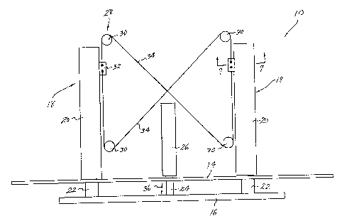
Fig. I is a plan view of the equalizer system of
this invention showing a first. preferred pulley
arrangement.
- Fjg. 2 is a plan view of the system of Fig. 1 in an
extended position.
Fig. 3 is a plan view of the equalizer showing a
second pulley arrangement.
Fig. 4 is a plan view of the equalizNr :~liowir~g a
third pulley arrangement.
Fig. 5 is a plan view of tlne equalizer used in a
four tube system.
Fig. 6 is a plan view of the system of Fig. 5 in an
extended position,.
Fig. ? is a sectional view taken along line 7-7 of
Fig. 1.
Descrir~tion of the Preferred Embodiments
The preferred embodiments herein described are not
intended to be exl7austive or to limit the invention to
the precise forms disclosec9. They are chosen and
described to explain the principles of the invention and
their application and practical u~ie to unable others
skilled in the art to utilize its teach3.ngs.

~0'~'~86~
3
Referring first to Fig. 1, reference numeral 10
generally designates a sliding support system commonly
used to support a slide-out room in a recreational
vehicle (riot shown) . support system 10 includes an outer
support rail 14 and a room frame rail 16. Tubu.'Lax~
supports 18 (two shown) include guide tube 20 and
telescoping extensible tube 22 which is slidably fitted
in guide tube 20 and attached to rail 16. Extension of
tube 22 is accomplished by the extension of piston rod 24
of hydraulic cylinder 26. Rod 24 is connected to rail 16
as shown.
The above description illustrates a conventional
slide-out room support system 10. Fig. 1 also
illustrates the equalizer system 28 of this invention.
Equalizer 28 includes two or more pulleys 30 ( four are
shown) which axe rotatably connected to the frame (not
shown) of the vehicle. Each slidable tube 22 includes a
connecting bracket 32 fixedly fastened thereto which
slides along with the tube 22 during extension and
retraction. A cable 34 is fixedly connected to each
bracket 32 and extends across each pulley 30.
As shown in Fig. '1, each guide tube 20 has a
longitudinal slot 21 to accommodate sliding movement of
bracket 32 relative to the guide tube. Bracket 32
extends outwardly of tube 22 and through slot 21 as
shown.
Operation of the slide-out room is conventional.
When desired, a user actuates hydraulic cylinder 26
through a switch or other conventional means. Rod 24
extends outwardly in the direction of arraw 36 to urge
frame rail 16 outwardly of rail 14. The connection of
rail 16 to slide tubes 22 causes extension of the slide
tubes relative to guide tubes 20 and rail 14.

4
As the tubes 22 extend relative to tubes 20, the
fixed connections of bracket 32 and cable 34 cause the
cable to be drawn across pulleys 30. If one of the slide
tubes 22 begins to extend further than the other slide
tube, 'the tension on cable 34 and bracket 32 increases to
slew its movement and allow the other slide tube to
"catch up." As such, sliding movement of tubes 22 is
equalizec9 to ensure that rail 16 remains substantially
parallel to rail 14 during extension.
This arrangement of equalizer 28 allows the use of
a single hydraulic cylinder in the system shown.
Previously, hydraulically driven systems of this type
required the use of a separate cylinder for each tube.
These prior systems also required precise calibration of
the cylinders to ensure equal movements of the slide
tubes during extension arid retraction.
Figs. 1 and 2 illustrate an "R" configuration of
pulleys 30 and cable 34. Figs. 3 and 4 illustrate
alternative configurations of the pulleys 30 and cables
34 and are illustrative of the multiplicity of
configurations which system 28 may take in practice.
Figs. 5 and 6 illustrate the use of equalizer system
40 with a support system 10' having a large number of
guide tubes 42 and slide tubes 44. Equalizer system 40
includes pulleys 46 and cable 48 positioned as shown in
the drawings. Cables 48 are connected to brackets 50
which are connected to each slide tube 44 and ride in
elongated slots 52 along with the moving slide tubes.
The principle of operation is the same as that described
for equalizer system 28.

~~'~'~8~~
Use of any of the er~ualizers 28, 40 shown enables
the calibration o.f multiple slide -tubes for synchronized
movement without providing a separate power driven
cylinder. for each individual tube. Although multiple
arrangements are shown, the invention is not lim9.ted to
the .forms, nor is the use limited to slide out rooms.

Representative Drawing
A single figure which represents the drawing illustrating the invention.
Administrative Status

2024-08-01:As part of the Next Generation Patents (NGP) transition, the Canadian Patents Database (CPD) now contains a more detailed Event History, which replicates the Event Log of our new back-office solution.

Please note that "Inactive:" events refers to events no longer in use in our new back-office solution.

For a clearer understanding of the status of the application/patent presented on this page, the site Disclaimer , as well as the definitions for Patent , Event History , Maintenance Fee  and Payment History  should be consulted.

Event History

Description Date
Inactive: IPC from MCD 2006-03-11
Time Limit for Reversal Expired 2004-09-09
Letter Sent 2003-09-09
Inactive: Office letter 2002-09-06
Grant by Issuance 2002-07-02
Inactive: Cover page published 2002-07-01
Pre-grant 2002-04-15
Inactive: Final fee received 2002-04-15
Letter Sent 2001-11-01
4 2001-10-17
Notice of Allowance is Issued 2001-10-17
Letter Sent 2001-10-17
Inactive: Approved for allowance (AFA) 2001-09-25
Inactive: Single transfer 2001-09-20
Inactive: Entity size changed 2001-08-16
Inactive: Office letter 2001-08-13
Inactive: Multiple transfers 2001-06-27
Amendment Received - Voluntary Amendment 1999-03-10
Amendment Received - Voluntary Amendment 1999-02-08
Letter Sent 1998-08-26
Inactive: Status info is complete as of Log entry date 1998-08-25
Inactive: Application prosecuted on TS as of Log entry date 1998-08-25
All Requirements for Examination Determined Compliant 1998-08-04
Request for Examination Requirements Determined Compliant 1998-08-04
Application Published (Open to Public Inspection) 1994-01-14

Abandonment History

There is no abandonment history.

Maintenance Fee

The last payment was received on 2001-08-13

Note : If the full payment has not been received on or before the date indicated, a further fee may be required which may be one of the following

  • the reinstatement fee;
  • the late payment fee; or
  • additional fee to reverse deemed expiry.

Patent fees are adjusted on the 1st of January every year. The amounts above are the current amounts if received by December 31 of the current year.
Please refer to the CIPO Patent Fees web page to see all current fee amounts.

Fee History

Fee Type Anniversary Year Due Date Paid Date
MF (application, 5th anniv.) - small 05 1997-09-09 1997-07-17
MF (application, 6th anniv.) - small 06 1998-09-09 1998-07-02
Request for examination - small 1998-08-04
MF (application, 7th anniv.) - small 07 1999-09-09 1999-07-06
MF (application, 8th anniv.) - small 08 2000-09-11 2000-07-21
MF (application, 9th anniv.) - standard 09 2001-09-10 2001-08-13
Final fee - standard 2002-04-15
MF (patent, 10th anniv.) - standard 2002-09-09 2002-08-20
Owners on Record

Note: Records showing the ownership history in alphabetical order.

Current Owners on Record
VT HOLDINGS II, INC.
Past Owners on Record
JAMES E., JR. DEWALD
PATRICK W. MCMANUS
Past Owners that do not appear in the "Owners on Record" listing will appear in other documentation within the application.
Documents

To view selected files, please enter reCAPTCHA code :


To view images, click a link in the Document Description column (Temporarily unavailable). To download the documents, select one or more checkboxes in the first column and then click the "Download Selected in PDF format (Zip Archive)" or the "Download Selected as Single PDF" button.

List of published and non-published patent-specific documents on the CPD .

If you have any difficulty accessing content, you can call the Client Service Centre at 1-866-997-1936 or send them an e-mail at CIPO Client Service Centre.


Document
Description 
Date
(yyyy-mm-dd) 
Number of pages   Size of Image (KB) 
Cover Page 1994-02-18 1 21
Description 1994-02-18 5 175
Claims 1994-02-18 2 74
Abstract 1994-02-18 1 10
Drawings 1994-02-18 7 113
Description 1999-03-09 5 142
Claims 1999-03-09 2 78
Cover Page 2002-06-11 1 31
Representative drawing 2002-06-11 1 8
Representative drawing 1999-06-27 1 10
Acknowledgement of Request for Examination 1998-08-25 1 194
Commissioner's Notice - Application Found Allowable 2001-10-16 1 166
Courtesy - Certificate of registration (related document(s)) 2001-10-31 1 113
Maintenance Fee Notice 2003-11-03 1 173
Correspondence 2002-04-14 1 25
Correspondence 2001-08-12 1 16
Correspondence 2001-08-12 1 23
Correspondence 2002-09-05 1 16
Fees 2002-09-08 2 58
Correspondence 2001-10-16 1 57
Fees 1996-07-15 1 53
Fees 1995-04-26 1 40
Fees 1994-05-03 1 65