Note: Descriptions are shown in the official language in which they were submitted.
207~
ACOUSTIC REFLECTION PROCESS FOR MOLECULAR
SENSING AND APPLICATIONS OF THE PROCESS
FIELD OF THE lNv~ lON
This invention relates to a process of sensing the
concentration of specific molecules in a fluid, that is, a
liquid or gas, by electrical measurements using a bulk
acoustic wave (BAW) quartz sensor. The molecules to be
sensed, called the analyte, bind specifically to molecules
on the surface of the sensor, called the receptor.
Acoustic waves generated in the interior of the sensor are
partially reflected from the surface of the sensor. The
reflected waves change as the analyte binds to the
receptor and this change is detected by means of electrical
measurements.
This invention further relates to applications of the
acoustic reflection process for sensing biomolecules in
general. An example of the application of the process is
the sensing of a specific DNA molecule in which case the
receptor-analyte molecules are complementary strands of
DNA. Other examples of applications of the process are the
sensing of drug-receptor interactions and sensing of
immunochemical reactions.
BACRGROUND OF THE lNV~:~. lON
There are basically two types of processes which can
be used to sense the concentration of specific molecules in
a liquid using a BAW quartz sensor. The two types of
processes may be called by the generic names, active and
passive. The active method is more descriptively and
commonly called the oscillator method. In this method the
BAW quartz sensor is part of an oscillator circuit. It is
connected between the output and input of the oscillator
amplifier and thereby provides positive feedback that
causes oscillation of the circuit. The resonant frequency
of the circuit is measured by an electronic counter. The
quartz sensor is itself active in the sense that it is
continuously controlling the frequency of oscillation of
~07~ 1 ~4
the circuit. The oscillator method is inadequate when
used to sense molecules in a liquid.
The acoustic reflection process is a passive method
in which the BAW quartz sensor is connected externally to
an instrument which applies voltages, which typically
vary sinusoidally with time, across the terminals of the
sensor. Signal voltages are measured at various
frequencies of the applied voltage. The quartz sensor
does not determine the frequency at which measurements
are made and in that sense the sensor itself is passive.
The acoustic reflection process does not have the
disadvantages of the oscillator method. Therefore, this
invention displaces the oscillator method.
The oscillator method has at least three limitations
when used to sense molecules in a liquid. Only one
electrical quantity is measured and so the
characterization of the sensor is incomplete. The
measured quantity is a frequency which is ideally the
series resonant frequency, defined as the lower of the
two frequencies for which the phase of impedance of the
sensor is zero. However, rarely is the measured
frequency the same as the series resonant frequency due
to unknown phase shifts elsewhere in the oscillator
circuit; this is the second limitation. Thirdly, the
oscillator method can be used only when the sensor is in
liquids of low viscosity.
The acoustic reflection process completely
characterizes a bulk acoustic wave quartz sensor. This
is achieved by making measurements over the complete
frequency spectrum of the resonant region of the quartz
sensor. The process can be used with the sensor in a
liquid of any viscosity.
8UNNARY OF THE l~.v~..lON
In accordance with an object of an aspect of the
invention is a passive process for specifically sensing
analyte molecules in a fluid by reflection of bulk
acoustic waves from a sensing surface of a bulk acoustic
- :~0781 ~4
wave quartz sensing device to which analyte molecules
bind, the sensing device comprising a thin quartz plate
having opposing surfaces, a thin electrically conductive
means on each of the two opposing surfaces, wherein at
least one of the conductive means is a sensing surface
and supports a plurality of receptors for which analyte
molecules have an affinity, the process comprises:
i) contacting a fluid in which analyte molecules
are suspected with the sensing surface;
ii) applying a voltage to the bulk acoustic wave
quartz sensing device to produce an electromagnetic field
in the quartz sensing device, the applied voltage being
one of a sinusoidal time-varying voltage or other
periodically or non-periodically varying voltage to
generate acoustic waves in the quartz device, directing
such acoustic waves at the sensing surface whereby
acoustic waves are reflected from the sensing surface;
and
iii) detecting a change in characteristic of
acoustic waves reflected from the sensing surface due to
analyte molecules binding the receptors, the change in
the reflected acoustic wave characteristic being measured
by the conductive means thereby detecting a change in the
electromagnetic field which is related to the amplitude
and phase of the reflected acoustic waves, the conductive
means directly detecting the change in electromagnetic
field by making two electrical measurements at one
frequency or at each of one or more than one frequency of
sinusoidal voltage applied to the sensing device, or
equivalent measurements for applied voltages varying non-
sinusoidally with time, the measured electrical
quantities being the incident voltage on the sensing
device and reflected voltage from the sensing device, or
applied voltage across the sensing device and current
flowing through the sensing device, or other equivalent
measured quantities.
, -~
.
2n7~
BRIEF DESCRIPTION OF THE DRAWINGS
Preferred embodiments of the invention are shown in
the drawings wherein:
Figure 1 is a schematic representation of the sensing
device having a layered construction;
Figure 2 is a schematic of the reflection of bulk
acoustic waves within the sensing device; and
Figure 3 is a section through the measuring apparatus
of this invention using a sensing device of Figure 1.
DET~TT~n DESCRIPTION OF THE PREFERRED ENBODINENTS
This invention relates to chemical sensors and
biosensors in a liquid or gas which are sensing devices
known as a bulk acoustic wave quartz sensors. This sensing
device is a piezoelectric quartz crystal, used for control
of frequency in electronic circuits, which has been
modified. The sensing device is described first and then
the process of molecular sensing is described.
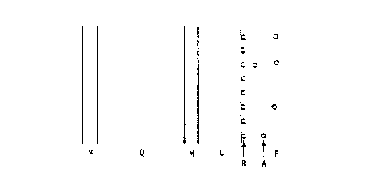
The structure of the sensing device is shown in Figure
1, which is a side view of the device not drawn to scale.
The unmodified piezoelectric quartz crystal is a thin plate
of quartz, region Q in Figure 1, and much thinner metal
layers, called electrodes, deposited on each face of the
quartz, regions M in Figure 1. The quartz crystal is
modified by attaching a coating, region C, to either one
electrode as shown in Figure 1, or to both electrodes. The
coating, C, consists in general of more than one layer; the
layers are not shown in the figure. The receptor, region
R in Figure 1, is attached to the surface of the coating.
The receptor is a layer of molecules represented by half
circles in Figure 1 which bind specifically to the
molecules to be sensed. The function of the coating is to
immobilize the receptor on the surface of the sensor. The
coating is not needed if the receptor can be attached
directly to the metal electrode. The regions MQMCR in
Figure 1 constitute the modified piezoelectric quartz
crystal, which will be henceforth called the sensor. If
the coating is attached to both electrodes then the
~07$1~4
receptor is attached to both coatings and the regions
RCMQMCR constitute the sensor.
A fluid (liquid or gas), region F in Figure 1, is in
contact with the surface of the sensor or the fluid is in
contact with both surfaces of the sensor. The fluid
contains the analyte, A, which is the assembly of molecules
to be sensed. The analyte binds chemically or physically
to the receptor. The analyte is represented in Figure 1 by
small circles and is shown before any of the analyte has
combined with the receptor. As the analyte accumulates on
the surface of the sensor, the properties of the surface
change. In addition, the properties of the fluid very near
the surface may also change. So in general the fluid is
divided into two regions: the interfacial region which is
very near to the surface of the sensor and the bulk region
which is the rest of the fluid. The interfacial region is
distinct from the bulk region when the fluid in the
interfacial region has one or more properties which are
different from the fluid in the bulk region. The
interfacial region may consist of more than one layer of
fluid, each layer of which has one or more properties
different from the other layers and from the bulk region.
The interfacial and bulk regions are not shown separately
in Figure 1.
The invention is the process of molecular sensing
which detects the accumulation of the analyte on the
surface of the sensor. A voltage is applied between the
two metal electrodes, regions M in Figure 1. The voltage
can vary periodically with time or it can be a voltage step
or a voltage pulse. The voltage of choice is a periodic
voltage with a sinusoidal waveform and the process will be
described in terms of this voltage, where hereafter the
word voltage refers to sinusoidal voltage. The voltage is
applied at one or more different frequencies over the
resonant region of the quartz sensor.
The voltage at each frequency produces an
electromagnetic field in the quartz which, in turn,
6 20~83 ~4
produces acoustic waves in the quartz by the piezoelectric
effect. The electromagnetic field is confined to the
quartz by the metal electrodes. But part of the acoustic
waves will flow out of the quartz and reach the receptor
layer, R in Figure 1. Part of the acoustic waves incident
on the receptor layer will be reflected and return to the
quartz where they will alter the electromagnetic field due
to the piezoelectric effect. This in turn will change the
electrical measurements made at the terminals of the
sensor.
The magnitude and phase of the acoustic waves which
are reflected from the receptor layer, R, and which return
to the quartz depend on the amount of analyte which is
bound to the receptor, which is related to the
concentration of analyte in the fluid, and therefore the
reflected acoustic waves carry that information back to the
quartz. The interfacial region of the fluid may also
change as the analyte binds to the receptor and that will
change the reflected waves which return to the quartz. But
the cause of the change of properties of both the sensor-
fluid interface and the interfacial region of the fluid is
the same: the binding of the analyte to the receptor.
Therefore the change of reflected waves is due to one
primary cause, the presence of the molecules to be sensed
in the fluid.
The details of the process of molecular sensing can be
described as follows. During the period of time when the
analyte binds to the receptor, region C and both regions M
will not change; only the properties of the surface of C,
consisting of the receptor and that part of the analyte
which is bound to the receptor, and perhaps the properties
of a thin region of fluid adjacent to the surface of region
C, with thickness from one to several monolayers of fluid
molecules, will change. Therefore M and C can be
considered as a single composite layer, denoted by L in
Figure 2. The other metal layer is not shown in Figure 2
~~ 7 ~0~1?~
because its effect on the acoustic waves in Q will remain
constant during the process of molecular sensing.
There will be multiple reflections of the acoustic
waves in region L of Figure 2. After a sufficient number
of transits of the acoustic waves in L, conditions in L
will reach a steady state such that the rate at which
acoustic energy is transmitted back into region Q plus the
rate at which it is transmitted into region F is equal to
the rate of acoustic energy entering L from Q. The
thickness of region F is large enough so that the acoustic
waves transmitted into the fluid, region F, are entirely
absorbed and therefore no acoustic energy returns to L from
F.
In the steady state, as defined above, there will be
acoustic waves traveling to the right and left in regions
Q and L, but only to the right in region F. The symbol, u,
in Figure 2 represents the particle displacement and the
arrow attached to u is the direction of the wave of
particle displacement. The wave of particle displacement is
the propagation of the particle motion from one particle to
a second particle adjacent to the first particle and from
the second particle to the third particle and so on. For
example, a thickness-shear wave is propagated in the quartz
of a sensor which has the orientation known as AT-cut and
in this case the particle displacement is in the direction
parallel to the surface of the quartz and therefore
perpendicular to the direction of the wave of particle
displacement. The first subscript on u in Figure 2 denotes
the following: i for incident, t for transmitted and r for
reflected. The total particle displacement wave in L is uLt
+ uLt and in Q, UQj + UQr~
It is well-known that in a system such as that of
Figure 2, the acoustic waves depend on a property of the
material of each of the three regions called the acoustic
impedance, defined as the product of density of the
material and phase velocity of the wave in the material.
But in this system the acoustic impedance of the three
8 ~7~
regions does not change during the process of molecular
sensing, that is, as the analyte binds to the receptor.
Rather, the properties of the interface between regions L
and F change as the analyte binds to the receptor. The
interface between regions L and F, the LF interface, means
in this context both the surface of the sensor in contact
with the fluid (surface of L in Figure 2) and the
interfacial region of the fluid when it is distinct from
the bulk region of the fluid (region F in Figure 2 is the
bulk region in this context). For example, one of the
properties of the sensor-fluid surface may be called the
interfacial viscosity which is a measure of the interaction
between the surface of L and the fluid molecules in contact
with the surface of L. It is the change in properties of
the LF interface that causes the change in distribution of
acoustic waves in Figure 2. As the analyte binds to the
receptor, the wave reflected from the LF interface, uLr,
changes and as a consequence in the steady state all waves
shown in Figure 2 will change. The acoustic waves in Q are
coupled to the potential in Q by the piezoelectric effect
and the potential affects the measurements made at the
terminals of the sensor.
In summary the process of molecular sensing consists
of the following sequence of events when the molecule to be
sensed is present in the fluid.
i) Analyte binds to the receptor at the LF interface
ii) Interfacial properties of the LF interface change
iii) Reflected acoustic waves from the LF interface
change
30 iv) Acoustic waves in the quartz change
v) Potential in the quartz changes
vi) Electrical quantities measured at the
terminals of the sensor change
The change of measured electrical quantities is related to
the concentration of the analyte which is present in the
fluid.
9 207~ ~A
Two electrical measurements are made at each frequency
of voltage applied to the electrodes of the sensor. The
measured quantities can be the voltage incident on the
sensor and the voltage reflected from the sensor, called
the network analysis measurements, or the voltage applied
across the sensor and current flowing through the sensor,
or other equivalent measurements. The two measurements
made at each frequency, the measured quantities, can be
combined to find the magnitude and phase of the impedance
of the sensor, which are called derived quantities, or the
measurements can be combined or presented in other ways.
There are several characteristic quantities which can
be found from the values of the derived quantities when
they are known at many different frequencies in the
resonant region of the sensor. For example, if the
magnitude and phase of impedance are the derived
quantities, then some of the characteristic quantities, but
not all, are the following: the values of minimum and
maximum magnitude of impedance, the frequencies at which
the magnitude of impedance is a minimum and maximum, the
value of maximum phase, the frequency at which the phase is
a maximum, the two frequencies at which the phase is zero
(the zero-phase frequencies do not always exist), the
values of minimum and maximum first derivatives with
respect to frequency (the slopes) of the magnitude and
phase of impedance, the frequencies at which the first
derivatives are a minimum and maximum, the values of
minimum, zero and maximum second derivatives with respect
to frequency (the curvatures) of the magnitude and phase of
impedance, and the frequencies at which the second
derivatives are a minimum, zero and maximum. As the
analyte binds to the receptor, the concentration of the
analyte can be determined by assessing the change of one or
more of the characteristic quantities.
The essential features of the measurement method are
shown in Figure 3 which is not drawn to scale. Figure 3 is
a cross-sectional view of the device 10 perpendicular to
2 ~
the plane of the sensor 12 and through the center of the
sensor 12. The broadly cross-hatched region 14 is a flow-
through cell 16 in which the sensor is clamped between two
O-rings 18 and 20. The fluid 22 (liquid or gas) is in
contact with one side 24 of the sensor in Figure 3, but the
fluid could make contact with both sides 24 or 26 of the
sensor. The electrodes 28, 30 on each face of the sensor
are connected by electrical conductors 32, 34 to the
measuring apparatus 36.
This invention also relates to applications of the
molecular sensing process of which the receptor or analyte
or both are biomolecules. Examples of applications follow
which are to be understood as illustrative of the scope of
the applications of the process and which are understood to
be non-limiting with respect to the appended claims.
EXAMPLES OF APPLICATION8
1. DNA Sensor
The analyte, A in Figure 1, is single-strand DNA. The
receptor, R in Figure 1, is complementary DNA, strands of
DNA which are complementary to the analyte. The electrode,
M in Figure 1, is gold. The coating, C in Figure 1,
consists of a thiol monolayer self-assembled on the gold
and a linking agent.
The DNA sensor detects interfacial nucleic acid
hybridization by the acoustic reflection process. An
unmodified piezoelectric quartz crystal with gold
electrodes is cleaned by plasma etching. The crystal is
then immersed in methanol which contains 2.2 % W/V 11-
mercaptoundecanoic acid (MUA) for twenty-four hours. The
crystal is washed with small amounts of acetone and dried
in a stream of clean nitrogen.
Single-strand DNA is covalently linked to the
carboxylic acid functionalities of MUA. This is achieved
by exposing the crystal with thiol on its surface to a 1:1
solution of 10 mg/mL 1-ethyl-3-(3-dimethylaminopropyl)-
carbodiimide hydrochloride (DEC) and l mg/mL denatured DNA
(which had been heated to 100~C for 20 minutes) for twelve
2~7~
11
hours at 5~C. The crystal is allowed to warm to room
temperature and then is washed extensively with distilled
water for five minutes and dried.
The amount of DNA immobilized on the sensor surface
can be determined by first removal with EDTA solution at
100~C followed by measurement of W absorbance at 260 nm.
The sensor is incorporated into the measurement system
of the acoustic reflection process and then exposed to
solutions of complementary single-strand DNA in EDTA and
Tris buffer solution of 42~C.
The magnitude and phase of impedance is measured at
many different frequencies in the resonant region of the
sensor and several characteristic quantities are found from
these experimental results. For example, the frequency of
maximum phase changes by an order of magnitude of 1000 Hz
when the complementary single-strand DNA is present in
solution.
2. 8ensor for Drug-Receptor Interactions
The analyte, A in Figure 1, is a bio-receptor from a
cell, identical molecules, usually proteins, to which a
drug is designed to bind. The receptor, R in Figure 1, is
an agonist, molecules that bind to the analyte when it is
in the cell and thereby trigger a cascade of biochemical
reactions in the cell. The word, receptor, has two
distinct meanings in this example: receptor, alone, means
the molecules immobilized on the surface of the sensor (R
in Figure 1) which bind to the analyte, and bio-receptor in
the phrase, bio-receptor from a cell, means the analyte.
The sensor for drug-receptor interactions is
incorporated in a flow injection analysis (FIA) system,
which is capable of stop-flow measurements. A particular
agonist for the bio-receptor from a cell is immobilized on
the sensor surface. In the FIA system, the bio-receptor
from a cell is introduced in a buffer liquid over the
sensor surface. Kinetic measurements by the acoustic
reflection process are made of the binding of the
71 Q~ 2_ ~ ~
12
bio-receptor from a cell to the agonist until equilibrium
is reached. At equilibrium, a certain fraction of the
agonist will be bound to the bio-receptor from a cell.
Then a drug, molecules which also bind to the bio-receptor
from a cell, is introduced in a liquid over the sensor
surface and measurements are made. Some of the occupied
agonist, the agonist which is bound to the bio-receptor
from a cell, will be displaced by the drug. Therefore, in
the presence of the drug the fraction of occupied agonist
will be less than the fraction in the absence of the drug.
This procedure constitutes a competitive binding assay of
drug-receptor interactions using the acoustic reflection
process.
Characteristic quantities are found from the
experimental results of the acoustic reflection process, as
in the DNA sensor application for example.
3. Sensor for Immunochemical Diagnostics
The analyte, A in Figure 1, is an antigen which is the
subject of an assay. The receptor, R in Figure 1, is an
antibody which specifically binds to the analyte.
The array described above requires linking of an
antibody, for example, IgG, to the surface of the gold
electrodes of the BAW sensor. Two general methods are used
for this purpose:
i) A film of protein A is deposited on the gold
electrode surface by placing drops of protein A
solution on the electrode followed by
evaporation. The protein A film/sensor
combination is then exposed to a buffered
solution of antibody. The antibody binds to the
protein A film.
ii) A film of polyacrylamide gel is placed on the
electrode surface. The thickness of the gel film
is about 50 ~m. After immersion of the gel in
flutaraldehyde solution for several hours at 40~C
followed by copious washing with water, the
polymer is treated with a solution of antibody
13 ~07~
for twenty-four hours at 2~C. Unreacted
glutaraldehyde functionalities are then
neutralized with L-lysine solution. After washing
the sensor is stored under 0.1% sodium oxide
solution and kept in the dark.
In a particular immunoassay, the BAW-antibody
combination is allowed to interact with the antigenic
species. Characteristic quantities are found from the
experimental results of the acoustic reflection process, as
in the DNA sensor application for example.
Although preferred embodiments of the invention are
described herein in detail, it will be understood by those
skilled in the art that variations may be made thereto
without departing from the spirit of the invention or the
scope of the appended claims.