Note: Descriptions are shown in the official language in which they were submitted.
20783~
' "Continuous self-cleaning filter for viscous fluids"
* * * * *
DESCRIPTIO~
The present invention relates to a self-cleaning
filter for viscous fluids.
More specifically, the present invention relatès
to a self-cleaning filter for viscous fluids particularly
designed to be employed on machines for the processing or
regeneration or recovery of plastics.
As is known, in machines for processing fluid
products and in particular those which regenerate or
recover plastics in general, the filters are one of the
most critical parts which i~fluence the processing cycle
and productivity of the machine.
Indeed, the filters usually employed require very
frequent cleaning which, in some cases, must be performed
every 5 to 10 minutes. This necessity obviously results
in high maintenance costs and lost production due to
stopping of the production process.
Another shortcoming is that the most common
- ~ilters presently in use, being substantially of the
metal wire typs or similar, are sub~ect to severe
~tres--s and ea~y yielding because they are sub~ected to
high op rating pres~ures on the order of 100-150bar as
2S reguired by t~e processing of plastics and/or fluids in
general.
Every cleaning and/or change of filter~ also
involves considerable waste of material under treatment.
By way of example, knowing that the present cost
of virgin polyethylene is approximately 1,500 liras per
2~783~6
kilogram, the cost of polyethylene to be regenerated
varies from 200 liras to 400 liras per kilogram and the
incidence of the above operations and resulting waste is
~ calculated at 50-60 liras per kilogram of virgin product.
Bearing in mind that, presently, only in Italy
approximately 50~,000 tonnes o~ plastic are regenerated
per year, it is clear that the investment involved is not
negligible.
The purpose of the present invention is to
eliminate the above shortcomings.
- More specifically, the purpose of the present
invention is to provide a filter for viscous fluids
particularly suited for application to machines for the
processing or regeneration or recovery of plastics which
would be self-cleaning and thus not reguire ~requent
cleaning andJor replacement and would be resistant
against stresses caused by the operating pressures.
In accordance with the present invention this and
other purposes are achieved by a continuous sel~-cleaning
~ilter which, in its essential lines, comprises a powered
hollow rotor whose surface consists o~ several ~iltering
layers superimposed and specifically a hollow internal
cylinder with drilling and sur~ace slotting, a screen or
cloth or ~-tal wire having predetermined cross section
2S wrapped on the internal cylinder in such a manner as to
~orm calibrated interstices, and an external ring or
~- cylinder with hole~ ~or the passage o~ the ~luids to be
; ~iltered.
The rotor i~ rotated in a cylindrical chamber to
wbich lead at least one inlet duct and discharge openings
2~78~.~6
with which are combined pressing and scraping means for
the dirty filtered residues. The outlet of the filtered
and recovered product is coaxial with the rotor axle and
comprises an internal pressure flow adjusting valve,
s which pressure is set so as to be always higher than that
present at the outlets of the waste and lower than that
of inlet of the products to be filtered.
A powered screw in the outlet duct allows
regulation of the quantity of impurities or waste
extracted and thus the difference in pressure between the
fluid inlet and outlet based on the pressure and
temperature at the various points of the filtering drum.
Some results which the continuous self-cleaning filter of
the present invention provides can be summarized as
lS follows:
- the powered rotor constitutes a continuous action
rotating drum filter in which the inlets of the
products to be filtered are arranged along at least
one longitudinal generating line and the outlets for
the filtQred waste or impurities are substantially
arranged along longitudinal generating lines
diametrically opposite the rormer, or oriented along
any preferred or functional arrangement depending on
the prodUcts to be treated and their characteristics;
- 25 - during ~iltering, the parts recovered through the
filtering layers Or the rotor inside the central
chamber Or the rotor to then be discharged through a
duct coaxial with the control valve while the waste~
are imprisoned in the beehive cells or passage holes
Or the external ring to be then expelled by pressure
2078356
difference from the inside to the outside opposite the
outlet ducts; and
- the continuous filtering and self-cleaning action is
achieved by the combination of continuous rotor
rotation and input of fluids to be filtered at a
pressure greater than that of discharge of the -
filtering fluids, which is in turn greater than the
atmospheric pressure of discharge of the impurities
and waste.
The advantages achieved by the continuous
self-cleaning filter of the present invention are
essentially the fact that self-cleaning of the filtering
drum avoids periodic stopping of the filter and
consequently increases the productivity of the system
with a considerable reduction of the costs for the fluid
products being recovered. In addition, the structure and
configuration of the filter of the present invention are
such that periodic general maintenance operations are
very limited.
Another advantage is that the filtering proces~
can be automatically controlled and programmed on the
ba~i~ of the proces~ing of fluid pressure and temperature
data ~t the various points o~ the filter and the
capability of pres-tting the pressers and scrapers by
2S means of the ~crew.
Anoth-r advantage is that the filter of the
pr-sQnt invention can be used advantageously not only for
the recovery o~ ~luid products to be regenerated but in
spocial production cycles such as for example of
continuous plastic film and the like thanks to its
20783~6
continuous operation and steady productivity with uniform
pressure drop between input and outlet.
The construction and functional characteristics of
the continuous self-cleaning filter for viscous fluids of
the present invention can be better understood from the
detailed description given below with reference to the
figures of the annexed drawings showing a preferred but
nonlimiting embodiment thereof and in which:
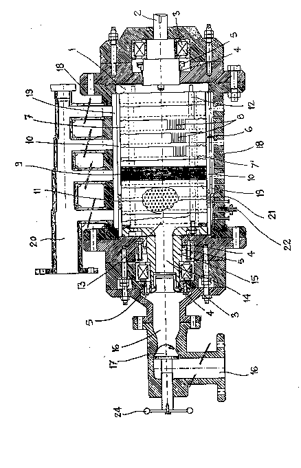
FIG. 1 shows a schematic longitudinal cross
section view of the continuous self-cleaning filter o~
the present invention,
FIG. 2 shows a schematic longitudinal cross
section view of an output duct for the dirty material
resulting from filtration, and
lS- FIG. 3 shows a schematic cross section view of the
output duct of FIG. 2.
With reference to the figures the continuous
self-cleaning ~ilter for viscous fluids of the present
invention especially suited for application to machines
employed in the processing and/or regeneration of
~ plastics substantially comprises an internal rotor (1)
. .
whose rotation axles are mounted on a bearing structure
or containing case ~18) by means o$ interposed bearings
(3), seals ~4), bushes (5) and other conventional sealing
y~tew~ de~igned to prevent the out~low Or ~luid to be
tr-ated.
The drive (2) o~ the rotor extends outside the
~earing structure. The central part o~ the rotor or
~ilter~ng drum (6) is ~ormed by a first hollow internal
cylinder (7) whose sur~ace is provided with holes or
2078356
, slots~(8) designed to ensure passage of fluid. On the
- external surface of the cylinder (7) is wrapped a layer
(9) of metal wire with a round cross section or a twisted
metal wire with polygonal cross section so that between
or a metal microdrilled sheet.
its turns there remain calibrated interstices~. Finally,
over said layer (g) is fitted a ring or cylindrical body
(10) provided on the surface with holes (11) for passage
of the fluid treated. The hollow rotor (1) can be
provided in accordance with different techniques or
10 configurations such as, for example, a plurality of
annular bodies (7') brought near with slotted peripheral
surfaces or by combining straight, undulated and/or
shaped packages of plates assembled on tie-rods (12). As
an alternative, the rotor can also be provided with
lS- ceramic filters or the like.
In the central part of said filtering drum (6) i9
a chamber (13) which comprises an outlet duct (14)
substantially coaxial with one of the supporting axles
(15) of the rotor (1) on the bearings (3). Said
supporting axle (15) is preferably opposite that of the
drive (2).
The outlet duct (14) is connected to a manifold
(16) on which i~ placed a manual or powered control valve
(17). The mani~old (16) i8 substantially ~oined to the
2S body or containing case in which is contained the
f~ltering drum (6) of the rotor (1). Between the
external surface of the cylindrical body (10) of the
filter~ng drum (6) and the internal one o~ the case (18)
i8 formad a toroidal cha~Dber (19).
2078356
The bearing structure or containing case (16) ~ B
provided on one side with at least one manifold (20) with
longitudinal generating line to supply the ~luid or
plastic product to be filtered into the toroidal chamber
(19 ? and, on the opposite side, with a series of ducts
(22) having generating lines and orientation opposite
those of th~ mani~olds (20) for outlet o~ waste or
impurities from said toroidal chamber (19). The outlet
zones o~ the impurities or waste are delimited by
conveying tiles (21? facing the external surface of the
cylindrical ring or body (10).
On the free surface of the tiles (21) are fixed
adjustable presser & scraper devices (23).
The fluid or plastic product to be filtered coming
at a pressure P1 from the supply manifold (20) is input
to the toroidal chamber (19).
During rotation of the rotor (1) the material
under pressure to be filtered is distributed over the
entire toroidal chamber (19) except the impurities and
waste outlet zones delimited by the tiles (21).
Because of the pressure Pl at the inlet, which can
reach even high values o~ 120-150bar, the material to be
~ilt-red i8 pushed through the spaces consisting o~ the
hol-~ (11) in the cylindrical body (10), the we~t or
2S meshes in the intermediate layer (9) o~ wire or metal
screen and holes or slots (8) in the internal cylinder
(7). In said phase, the ~iltered material to be
recovered passes between the above we~ts or meshes in the
layer (9), between the holes or slots (8) in the internal
cylinder ~7) and is collected in the central chamber (13)
20783~6
of the filtering drum (6) in which is present a pressure
P2 lower than th~ input pressure Pl~ e.g. 100-120bar.
~ he pressure P2 in the central chamber (13) is in
turn higher than the pressure pO present beneath the
tiles (21) of the impurities and waste outlet ducts (22).
- The impurities or waste have a configuration and
- consistency higher than those of thQ recoverable fluid
and are trapped in the beehive cells formed by the holes
(11) o~ the external cylinder (10) of the drum (6) until,
during rotation of the rotor (1), the material still to
be filtered exerts a pressure on them from the outside
inward.
The rotor (1) in its rotary motion brings the
holes (11) of the ring (10) cyclically opposite a tile
(21).
When an external surface zone o~ the cylinder (10)
encounters in rotation one of the tiles (21) the waste in
the corresponding holes (11) escapes the pressure Pl and
is subject to the pressure pO present beneath the tiles.
Said pressure pO being less than that P2 present in the
central chamber (13), the waste is pushed out of the
holes (11) and collected by presser & scraper devices
t23) beneath the tiles (21) and conveyed into the outlet
duct~ ~22).
Expulsion of the wastes from the holes (11) of the
external cylinder (10) thus generates a self-cleaning
action at each tile (21). As the rotor (1) contlnues to
rotate each cleaned zone of the cylinder (10) again
passes opposite the toroidal chamber (19) and resumes its
filtering action. The ~iltered and/or regenerated
2~78356
product from the central chamber (13) is then made to
flow through the outlet duct (14) and the m~nifold (16).
The valve (17) is used to adjust the aperture and hold
steady the outlet pressure P2 or better yet to hold
steady the pressure difference between Pl and P2.
The outlet pressure pO of the waste is preferably
equal to atmospheric pressure.
Depending on application requirements, the control
valve (17) can be equipped with a manual handwheel (24)
or powered. Similarly the presser & scraper devices (23)
can be equipped with position and pressure adjusters of
the screw type (25) with manual operation or with
hydraulic pistons which can provide uniform adherence of
the presser & scraper device (23) on the drum (6) even in
the presence of any deformations of the drum.
To control the pressure pO inside the duct (22) a
powered screw can be mounted inside the duct with the
function of extracting the impurities and waste. The
quantity of impurities extracted and ths pressure pO can
be varied by varying the rotation speed of the screw. By
means of this device the self-cleaning filter for viscous
rluids Or the present invention can be used in
conventional or automated plant~ ln which, by electronic
proces~lng Or the temperature and pressure data taken by
sensors in appropriate points of the filter, it is
possible to automatically control the continuous
riltering process and achieve steady pressure o~ the
~iltered product at the outlet or steady pressure
diffQrence between the inlet and the outlet. Thanks to
these characteristics the self-cleaning filter of the
ll ~
2078356.
present invention can be used also for special
applications such as for example those concerned with the
continuous production of plastic films. For this
application, indeed, uniformity in the motion
characteristics of the viscous fluids such as pressure,
temperature, flowrate, viscosity and so forth eliminates
the actual variations in thickness found in continuously
manufactured plastic films.