Language selection

Search

Patent 2078460 Summary

Third-party information liability

Some of the information on this Web page has been provided by external sources. The Government of Canada is not responsible for the accuracy, reliability or currency of the information supplied by external sources. Users wishing to rely upon this information should consult directly with the source of the information. Content provided by external sources is not subject to official languages, privacy and accessibility requirements.

Claims and Abstract availability

Any discrepancies in the text and image of the Claims and Abstract are due to differing posting times. Text of the Claims and Abstract are posted:

  • At the time the application is open to public inspection;
  • At the time of issue of the patent (grant).
(12) Patent Application: (11) CA 2078460
(54) English Title: SCREENED RFI THROUGH-LET
(54) French Title: DISPOSITIF DE BLINDAGE CONTRE LES SIGNAUX RADIOFREQUENCE
Status: Dead
Bibliographic Data
(51) International Patent Classification (IPC):
  • H05K 9/00 (2006.01)
  • H01R 13/658 (2011.01)
  • H01R 13/658 (2006.01)
(72) Inventors :
  • HANSSON, KJELL OLOV (Sweden)
  • OVANFORS, ERIK LENNART (Sweden)
(73) Owners :
  • TELEFONAKTIEBOLAGET LM ERICSSON (Sweden)
(71) Applicants :
(74) Agent: MARKS & CLERK
(74) Associate agent:
(45) Issued:
(22) Filed Date: 1992-09-17
(41) Open to Public Inspection: 1993-03-28
Examination requested: 1998-11-03
Availability of licence: N/A
(25) Language of filing: English

Patent Cooperation Treaty (PCT): No

(30) Application Priority Data:
Application No. Country/Territory Date
9102822-5 Sweden 1991-09-27

Abstracts

English Abstract


ABSTRACT

The present invention relates to an RFI through-let for screening
signals transmitted between different components, for instance
circuit boards, of which one component is arranged in a screened
space. The through-let includes signal-transmission through-let
capacitors which are mounted in a screen plate intended to be
positioned in a rectangular opening in the side-wall of the
screened space. According to the invention, the screen plate (3)
is comprised of a front part (3) which includes a rectangular,
generally flat plate having tongues or tabs (7) disposed along the
sides thereof and also having a central, rectangular hollow (9),
and a holding part (5) which is soldered firmly in the vicinity of
the hollow (9) of the front part (3). The holding part (5) includes
a flat plate whose long sides are bent to form guide flanges (11)
which extend perpendicularly downwards away from the front part
(3), along a first line (A) corresponding to the long sides of the
opening (6), and along a second line (B) downwardly of the first
line are further bent inwardly towards one another. Parts (12)
punched-out along the first line (A) cause shoulders (13) to be
formed in the second bending operation, these shoulders projecting
upwards and outwards towards the front part and are intended to
grip-in behind the side-wall (4) of the space when fitting the
screen plate (1) and therewith hold the screen plate firmly in the
opening.


Claims

Note: Claims are shown in the official language in which they were submitted.


THE EMBODIMENTS OF THE INVENTION IN WHICH AN EXCLUSIVE
PROPERTY OR PRIVILEGE IS CLAIMED ARE DEFINED AS FOLLOWS:
1. An RFI through-let for screening signals transmitted between
different components, for instance circuit boards, of which one is
arranged in a screened space, comprising through-let capacitors
for signal transmission mounted in a screen plate intended for
positioning in a rectangular opening in the side-wall of the
screened space, c h a r a c t e r i z e d in that the screen plate.
(3) comprises a front part (3) which includes a rectangular,
generally flat plate with tongues or tabs (7) disposed along the
sides thereof and having a central, rectangular hollow (9), and
further comprising a holding part (5) which is soldered firmly to
the hollow (9) of the front part (3) and which includes a flat
plate whose long sides are bent to form right-angled guide flanges
(11) which extend down from the front part (3) along a first line
(A) corresponding to the long sides of the opening (6) and along
a second line (B) downwardly of the first line are bent further
inwards towards one another, wherein parts (12) punched-out along
the first line (A) result in the formation of shoulders (13) in the
second bending operation, these shoulders projecting upwardly and
outwardly towards said front part and being adapted to grip-in
behind the side-wall (4) of the space when fitting the screen
plate (1), whereby holding the screen plate firmly in said
opening.


2. A through-let according to Claim 1, c h a r a c t e r i z e d
in that the front part (3) and the holding part (5) are provided
with mutually coinciding holes in which the signal transmission
capacitors (2) are firmly soldered.


3. A through let according to Claim 1, c h a r a c t e r i z e d
in that the tongues (7) are provided with beads (8) which face
towards the side-wall (4) of the space.


4. A through-let according to Claim 1, c h a r a c t e r i z e d
in that the holding part (5) is bent upwards at its short sides
towards the front part to form positioning flanges (10) which
determine the longitudinal position of the screen plate (1) in the
opening (6).


Description

Note: Descriptions are shown in the official language in which they were submitted.


20 ~8~D

~ ~RE~D ~ O~ L~

TECHNICAL FIELD

The present invention relates to a RFI through-let for screening
signals transmitted between different components, for instance
circuit boards, of which components one is mounted in a screened
space, comprising signal transmission through-let capacikors
which are mounted in a screening plate intended to be mounted in
a rectangular opening in the side wall of the screened space.

BACKGROUND ART

Screened RFI-signal through-lets (RFI = Radio Frequerlcy Inter-
ference) of the aforesaid kind are known to the art. These
through-lets, however, are often of complicated construction and
the work i~volved in fitting the actual through-let and in
mounting the through-let in the associated equipment is time-
consuming. As a result, dificulties arise in achieving a complet~screen around the through-let, and also results in problem~ of
keeping the through~let in position in the ~creen wall.

DISCLOSURE OF THE INVENTION

Th~ object of the present invention is to provide a screened RFI
through let vf the aforesaid kind which is of simple and reliable
construction,which canbefittedwithout requiringtime-consuming
procedures, and which can be applied simply and quickly and which
will remain seated in the opening, while nevertheless affording~a
fully safe screen. This i5 achieved with a through-let having the
characteristic features set forth in the ~ollowing Cla:ims.

Thus, the advantages a~forded by the inventive through-:Let reside
in a simple construction comprising only a ~ew parts, rel;.able
screening, and rapid fittlng and application.

Further objects of the invention and advantages afforded thereby
will b~ apparent from the following description, in which the

2 2 ~

invention is described in more detail with re~erence to~a prefer-
red exemplifying embodiment thereof and also with re~erence to the
accompanying drawing.

BRIEF DESCRIPTIO~ OF THE DRAWING

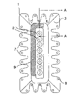
Figure 1 is a top view of an inventive ~FI through-let.
Figure 2 illustrates the through-let in side view and partially in
- section, and shows th~ through-let mounted in a chassis.
Figure 3 is another side view of the through-let.
Figure 4 illustrates a detail of the through-let.

BEST MODE OF C~RRYING OUT THE INVENTION

Figure 1 is a top view of the inventive RFI through-let~ The
through-let includes a screen plate 1 in which a number of signal-
transmission through-let capacitors 2 are mounted. The capacitors
2 are connected to electronic components, such as circuit boards,
in a suitable manner, of which components one is mounted in a
screened space. The described and illustrated embodiment has eight
capacitors, although it will be understood that this number can be
vaxied in accordance with the requiremenk for necessary signal
transmissions.

The screen plate 1 is comprised of kwo parts, a ~ront part 3 which
lies again~t the side-wall 4 o~ khe screened space~ and a holding
part 5 ~hich hold~ the through-let in position in an opening 6 in
the side-wall of the space, see Figures 2 and 3. The front part
comprises a rectangular, generally flat plate having disposed
along the sides thereof tab~ or tongues 7 which lie in resilient,
screening contact with the side-wall 4. Contact with the side-wall
can be improved by providing the tongues 7 with projections or
beads 8. The plate is provided with a central hollow 9 which has
disposed in the ~lat bottom thereo~ a number o~ holes, the number
correspondin~ to the number of signal transmission capacitors 2.

The holding part 5 comprises a rectangular flat plate whose two
opposing short-sides have been bent "upl' at right angles against

3 ~ ~ 7 ~


the front part 3 when the screen plate 1 is fitted, to form
positioni~g flanges 10 which determine the position of the screen
plate longitudinally in the opening 6, as illustrated in Figure 2~
As will be seen from Figure 3, the long sides o~ the holding part
5 are first bent "down" at right angles along a line A correspon-
ding to the long sides of the opening 6 away from the front part,
and are thereafter further bent, slightly inwards towards one
another along a line B to form guide ~langes 11 which guide the
screen plate 1 in the opening when fitting the through-let. Two U-
shaped parts 12 punched-out along the line A on each long side
cause shoulders 13 to be formed when bending along the line B,
'chese shoulders projecting obliquely upwards and outwards in
relation to the front part 3. The shoulders 13 are adapted to snap-
in behind the side-wall 4 of the space when fit~ing the screen
plate 1/ and to hold the screen plate in position in the opening
6. The holding part 5 is also provided with a number of holes
correspondin~ to the number of signal transmission capacitors 2.

The screen plate 1 is assembled by soldering together the front
part 3 and the holding part 5, with the holes in respectiYe parts
?O coinciding with one another, whereafter the signal transmission
capacitors 2 are mounted in the holes and soldered therein. The
screen plate is fitted by placing the screen plate in the opening
6, wherein the guide flanges 11 guide the screen plate laterally
and the positioning ~langes guide the plate longitudinally. The
shoulders 13 snap~in behind the side-wall ~ and hold the screen
plate firmly in position.

It will be understood that the invention is not restricted to the
a~oredescribed and illustrated embodiment thereoft and th~t
modifications can be made within the scope o~ the following
Claims.

Representative Drawing
A single figure which represents the drawing illustrating the invention.
Administrative Status

For a clearer understanding of the status of the application/patent presented on this page, the site Disclaimer , as well as the definitions for Patent , Administrative Status , Maintenance Fee  and Payment History  should be consulted.

Administrative Status

Title Date
Forecasted Issue Date Unavailable
(22) Filed 1992-09-17
(41) Open to Public Inspection 1993-03-28
Examination Requested 1998-11-03
Dead Application 2002-09-17

Abandonment History

Abandonment Date Reason Reinstatement Date
2001-09-17 FAILURE TO PAY APPLICATION MAINTENANCE FEE

Payment History

Fee Type Anniversary Year Due Date Amount Paid Paid Date
Application Fee $0.00 1992-09-17
Registration of a document - section 124 $0.00 1993-04-15
Maintenance Fee - Application - New Act 2 1994-09-19 $100.00 1994-07-27
Maintenance Fee - Application - New Act 3 1995-09-18 $100.00 1995-08-15
Maintenance Fee - Application - New Act 4 1996-09-17 $100.00 1996-07-11
Maintenance Fee - Application - New Act 5 1997-09-17 $150.00 1997-08-05
Maintenance Fee - Application - New Act 6 1998-09-17 $150.00 1998-09-01
Request for Examination $400.00 1998-11-03
Maintenance Fee - Application - New Act 7 1999-09-17 $150.00 1999-09-03
Maintenance Fee - Application - New Act 8 2000-09-18 $150.00 2000-09-12
Owners on Record

Note: Records showing the ownership history in alphabetical order.

Current Owners on Record
TELEFONAKTIEBOLAGET LM ERICSSON
Past Owners on Record
HANSSON, KJELL OLOV
OVANFORS, ERIK LENNART
Past Owners that do not appear in the "Owners on Record" listing will appear in other documentation within the application.
Documents

To view selected files, please enter reCAPTCHA code :


To view images, click a link in the Document Description column. To download the documents, select one or more checkboxes in the first column and then click the "Download Selected in PDF format (Zip Archive)" or the "Download Selected as Single PDF" button.

List of published and non-published patent-specific documents on the CPD .

If you have any difficulty accessing content, you can call the Client Service Centre at 1-866-997-1936 or send them an e-mail at CIPO Client Service Centre.


Document
Description 
Date
(yyyy-mm-dd) 
Number of pages   Size of Image (KB) 
Drawings 1994-01-29 1 50
Description 1994-01-29 3 175
Claims 1994-01-29 1 66
Representative Drawing 1998-10-26 1 13
Cover Page 1994-01-29 1 18
Abstract 1994-01-29 1 45
Prosecution-Amendment 1998-11-03 1 35
Assignment 1992-09-17 5 158
Fees 1996-07-11 1 58
Fees 1995-08-15 1 65
Fees 1994-07-27 1 87