Language selection

Search

Patent 2078617 Summary

Third-party information liability

Some of the information on this Web page has been provided by external sources. The Government of Canada is not responsible for the accuracy, reliability or currency of the information supplied by external sources. Users wishing to rely upon this information should consult directly with the source of the information. Content provided by external sources is not subject to official languages, privacy and accessibility requirements.

Claims and Abstract availability

Any discrepancies in the text and image of the Claims and Abstract are due to differing posting times. Text of the Claims and Abstract are posted:

  • At the time the application is open to public inspection;
  • At the time of issue of the patent (grant).
(12) Patent Application: (11) CA 2078617
(54) English Title: MOBILE SHREDDER
(54) French Title: DECHIQUETEUR MOBILE
Status: Deemed Abandoned and Beyond the Period of Reinstatement - Pending Response to Notice of Disregarded Communication
Bibliographic Data
Abstracts

English Abstract


ABSTRACT OF THE DISCLOSURE
In general, paper shredders cut paper into narrow
strips, and for such purpose, include narrow, somewhat
delicate blades. A paper spreader for receiving shredded
paper from a shredder, and compacting and cutting the paper
into smaller pieces before distributing the paper pieces to a
pile includes an outlet chute for receiving shredded paper
from a shredder, an auger inclined upwardly and outwardly from
the chute for compacting and conveying shredded paper away
from the shredder, a deflector plate at the outer top end of
the auger for deflecting paper carried by the auger, and a
blade on the deflector plate extending tangentially of the
auger shaft for cooperating with a sharpened, upwardly
tapering auger flight to shear the paper carried by the auger.


Claims

Note: Claims are shown in the official language in which they were submitted.

THE EMBODIMENTS OF THE INVENTION IN WHICH AN
EXCLUSIVE PROPERTY OR PRIVILEGE IS CLAIMED ARE DEFINED AS
FOLLOWS:
1. A paper spreader device for use in combination
with a paper shredder comprising outlet chute means on the
paper shredder for receiving shredded paper; auger means
extending upwardly and outwardly from said chute means for
conveying the shredded paper away from said chute means; and
blade means proximate the outer end of said auger means for
cutting the shredded paper from said auger means, whereby the
shredded paper is removed from auger means for gravity
distribution over an area beneath the outer end of said auger
means.
2. A device according to claim 1, wherein said
auger means includes shaft means; and helical flight means on
said shaft means, at least the outer end of said flight means
being sharp to define a cutting edge for preventing
accumulation of shredded paper on said auger means and for
cutting the shredded paper into small pieces.
3. A device according to claim 2, wherein said
flight means tapers towards the outer end thereof to
facilitate shearing action between said auger means and said
blade means.
4. A device according to claim 3, wherein said
auger means is inclined by an angle of approximately 37 to
the horizontal.

5. A device according to claim 3, including
deflector plate means carrying said blade means for deflecting
shredded paper from said auger means.
6. A device according to claim 5, wherein said
blade means is parallel to the longitudinal axis of said auger
shaft means, said blade means extending substantially
tangentially of said shaft means.
7. A device according to claim 6, wherein said
chute means is arcuate, extending around the bottom end of
said auger means for feeding shredded paper to said auger
means.

Description

Note: Descriptions are shown in the official language in which they were submitted.


2~78~17
This invention relates to a spreader device for use
in combination with a paper shredder.
~ore specifically, the invention relates to a device
for cutting, mixing, compacting and spreading strips of paper
discharged from a paper shredder.
Paper shredders usually include a series of
rotating cutting tools for shredding paper into thin strips.
Ideally the strips are so thin that they cannot readily be
J reassembled to form a readable sheet. Obviously, the thinner
the strips, the less the likelihood that they can be
reconstructed to form the original sheet. However, the
cutting of very thin strips requires thin cutting tools, which
are fragile and somewhat inefficient.
A solution to the problem is the use of a multi-
stage shredder for slicing paper into strips and dicing the
strips. Devices of this type are described in United States
Patents Nos. 4,068,805, issued to F. Oswald on January 17,
1978, and 4,124,169, issued to Takefumi Hatanaka on November
7, 1978. However, the patented devices are somewhat
complicated, including a large number of moving parts.
I Therefore, such apparatus would be expensive to produce and in
all likelihood require frequent maintenance. Moreover,
neither device provides any means for removing shr dded paper
from the vicinity of the shredder.
The object of the present invention is to provide a
solution to the above problems in the form of a relatively
':~
i "~,; "~, , , ,,,"", ,, ,,", " ,~",, ~ ,, ,,,,, ,,,; ~, ~:~ , ~", ~ " ,, ,, ," ,~,~ ,, ,"~, ", ", ~, ", "
i . . ,.. . . , , . ... :- . : : .~ :

2~78~17
simple spreader device for use with a paper shredder which
removes shredded paper from the shredder, and which further
processes the paper to make it more difficult to reassemble :
the pieces into a coherent whole.
Accordingly, the present invention relates to a
paper spreader device for use in combination with a paper
shredder comprising outlet chute means on the paper shredder
for receiving shredded paper; auger means extending upwardly
and outwardly from said chute means for conveying the shredded
paper away from said chute means; and blade means proximate
the outer end of said auger means for cutting the shredded
paper from said auger means, whereby the shredded paper is
removed from auger means for gravity distribution over an
area beneath the outer end of said auger means.
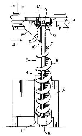
The invention will be described in greater detail -
with reference to the accompanying drawings, which illustrate
a preferred embodiment of the invention, and wherein:
Figure 1 is a perspective view of a spreader device
in accordance with the present invention;
Figure 2 is a perspective view of the top end of the
device of Fig. 1 from the side opposite Fig. l;
Figure 3 is a cross section taken generally along
line III-III of Fig. l; and
Figure 4 is a side view of the lower end of the
device of Fig. 1.
. :. ., , : , , ~ ~: .

2~7~617
With reference to the drawings, the spreader device
of the present invention includes an arcuate chute 1 of
semicircular cross section mounted on the lower discharge end
of a conventional paper shredder 2. The shredder 2 is an off- -
the-shelf piece of hardware which is intended to shred paper
into thin strips (not shown). The chute 2 extends outwardly
, from beneath the shredder 2 for collecting the strips of pager
~, discharge from the shredder.
An auger generally indicated at 3 extends upwardly
and outwardly from the chute 1 for conveying shredded paper
s away from the shredder 2. In order to achieve a certain
i degree of wadding of the already shredded paper, the auger 3- is rotated at a slower speed than the discharge rate of theshredder 2. The preferred angle of the auger is 37 to the
horizontal. The auger 3 includes an elongated shaft 4
extending through a lower end wall 5 (Fig. 4) of the chute 2
and a helical flight 6. The shaft 4 and the flight 6 are
rotated by a motor 8 connected to the bottom end of the shaft.
The upper end 9 of the shaft 4 rotates in a pillow block
bearing 10, which is mounted on a plate 12 (Fig~ 1) extending
downwardly from a beam 13. A pair of beams 13 are mounted in
a truck (not shown) or other vehicle when the
shredder/distribution device combination is to be portable.
For a fixed installation, the beams 13 are mounted in a large
container, which houses the shredder 2. The outer edges 14 of
''~ '
;,, .. .: ` . ,, . . ` , . ~,.. .. . .

. 207g~17 ,:,
the auger flight 6 are sharpened for facilitating additional
shredding of the already shredded paper.
A deflector plate 15 is connected to and extends
downwardly from the beams 13 to a position adjacent the auger
3. A blade 16 is attached to the lower end of the plate 15 by
bolts 17. The blade 16 is approximately tangential to the
auger 3. The upper end of the auger flight 6 is tapered, and
the outer edge 18 thereof is sharpened 50 that there is a
shearing action between the flight 6 and the blade 16. Thus,
the already shredded paper is cut into smaller pieces as it is
sheared from the auger while the tapered and sharpened flight
6 cuts wadded material in a scissor-like manner. The finely
shredded paper falls to form a pile (not shown) beneath the
upper end of the auger 3. Shredded paper rising on the auger
3 into contact with the blade 16 and the plate 15 is
compacted in the area between the plate 15 and a reinforcing
plate 19 (Fig. 2) extending downwardly from one beam 13 to one
edge of the plate 15.
Because the device of the present invention effects
~; 20 additional chopping and mixing of the paper, it is not ;
necessary that the shredder cut the paper into very thin
., .
strips. Therefore, wider and stronger cutting tools can be
used, making the shredder more productive and efficient.
~ 4
~: "~': '
~' , .
~ '' .

Representative Drawing
A single figure which represents the drawing illustrating the invention.
Administrative Status

2024-08-01:As part of the Next Generation Patents (NGP) transition, the Canadian Patents Database (CPD) now contains a more detailed Event History, which replicates the Event Log of our new back-office solution.

Please note that "Inactive:" events refers to events no longer in use in our new back-office solution.

For a clearer understanding of the status of the application/patent presented on this page, the site Disclaimer , as well as the definitions for Patent , Event History , Maintenance Fee  and Payment History  should be consulted.

Event History

Description Date
Revocation of Agent Requirements Determined Compliant 2020-09-01
Inactive: IPC from MCD 2006-03-11
Inactive: Inventor deleted 2002-06-17
Application Not Reinstated by Deadline 1995-03-18
Time Limit for Reversal Expired 1995-03-18
Inactive: Adhoc Request Documented 1994-09-19
Deemed Abandoned - Failure to Respond to Maintenance Fee Notice 1994-09-19
Application Published (Open to Public Inspection) 1994-03-19

Abandonment History

Abandonment Date Reason Reinstatement Date
1994-09-19
Owners on Record

Note: Records showing the ownership history in alphabetical order.

Current Owners on Record
W. LYLE PORTZ
Past Owners on Record
None
Past Owners that do not appear in the "Owners on Record" listing will appear in other documentation within the application.
Documents

To view selected files, please enter reCAPTCHA code :


To view images, click a link in the Document Description column. To download the documents, select one or more checkboxes in the first column and then click the "Download Selected in PDF format (Zip Archive)" or the "Download Selected as Single PDF" button.

List of published and non-published patent-specific documents on the CPD .

If you have any difficulty accessing content, you can call the Client Service Centre at 1-866-997-1936 or send them an e-mail at CIPO Client Service Centre.


Document
Description 
Date
(yyyy-mm-dd) 
Number of pages   Size of Image (KB) 
Claims 1994-03-18 2 73
Drawings 1994-03-18 2 66
Abstract 1994-03-18 1 40
Descriptions 1994-03-18 4 184
Representative drawing 1998-07-29 1 13