Language selection

Search

Patent 2079142 Summary

Third-party information liability

Some of the information on this Web page has been provided by external sources. The Government of Canada is not responsible for the accuracy, reliability or currency of the information supplied by external sources. Users wishing to rely upon this information should consult directly with the source of the information. Content provided by external sources is not subject to official languages, privacy and accessibility requirements.

Claims and Abstract availability

Any discrepancies in the text and image of the Claims and Abstract are due to differing posting times. Text of the Claims and Abstract are posted:

  • At the time the application is open to public inspection;
  • At the time of issue of the patent (grant).
(12) Patent Application: (11) CA 2079142
(54) English Title: MECHANISM FOR ADVANCING PACKAGE BLANKS
(54) French Title: MECANISME TRANSPORTEUR DE DECOUPES
Status: Deemed Abandoned and Beyond the Period of Reinstatement - Pending Response to Notice of Disregarded Communication
Bibliographic Data
(51) International Patent Classification (IPC):
  • B65H 05/02 (2006.01)
  • B65B 41/10 (2006.01)
  • B65B 43/22 (2006.01)
(72) Inventors :
  • JANSON, MAGNUS (Sweden)
  • OLANDER, JONNY (Sweden)
(73) Owners :
  • TETRA LAVAL HOLDINGS & FINANCE S.A.
(71) Applicants :
  • TETRA LAVAL HOLDINGS & FINANCE S.A. (Switzerland)
(74) Agent: MARKS & CLERK
(74) Associate agent:
(45) Issued:
(22) Filed Date: 1992-09-25
(41) Open to Public Inspection: 1993-04-03
Examination requested: 1999-08-13
Availability of licence: N/A
Dedicated to the Public: N/A
(25) Language of filing: English

Patent Cooperation Treaty (PCT): No

(30) Application Priority Data:
Application No. Country/Territory Date
9102849-8 (Sweden) 1991-10-02

Abstracts

English Abstract


ABSTRACT OF THE DISCLOSURE
The invention relates to a mechanism for advancing flat-laid package
blanks (10) disposed in a magazine (14).
A shaft (1) extending through the mechanism at right angles to the
magazine (14) is journalled by means of a free-wheel hub (5) so that it may
rotate in only one direction. The shaft (1) is urged against at least one
endless elastic belt (9) which interconnects two or more wheels (11). In its
turn, the belt (9) presses against the flat-laid package blanks (10).
The free-wheel hub (5) is surrounded by a lever (6), reciprocally
pivotal and connected to a drive unit (8). When the lever (6) is pivoted in the
one direction, the movement is transferred via the shaft (1) to the belt (9)
and the package blanks (10) are fed forwardly in the magazine (14). When
the lever (6) is pivoted in the other direction, the free-wheel hub (5) locks
and no movement is transmitted to the belt (9) which might counteract the
forward advancement of the package blanks (10) in the magazine (14).
Publication Figure: Fig. 2.


Claims

Note: Claims are shown in the official language in which they were submitted.

THE EMBODIMENTS OF THE INVENTION IN WHICH AN EXCLUSIVE
PROPERTY OR PRIVILEGE IS CLAIMED ARE DEFINED AS FOLLOWS:
1. A mechanism for the individual advancement of flat-laid package
blanks (10) in a magazine, characterized in that the mechanism
includes a shalt (1) journalled so that it may rotate in only one direction, a
lever (6) cooperating with said shaft (1) and reciprocally pivotal and
connected to a drive unit (8), the shaft (1 ) being urged against at least one
endless elastic belt (9) oriented in the longitudinal direction of the
magazine, the belt interconnecting two or more wheels (11) and, in its turn,
being urged against the upper edge of the package blanks.
2. The mechanism as claimed in Claim 1, characterized in that the
shaft (1) is locked in its one direction of rotation by means of a free-wheel
hub (5).
3. The mechanism as claimed in Claim 1, characterized in that the
lever (6) receives its movement via a piston rod (7).
4. The mechanism as claimed in Claim 3, characterized in that the
drive unit (8) consists of a pneumatic piston and cylinder assembly.
5. The mechanism as claimed in Claim 1, characterized in that the
lever (6) receives its movement via a cam.
6. The mechanism as claimed in Claim 1, characterized in that the
shaft (1) is urged against the belt (9) at a point (13) between the two wheels
(11).
7. The mechanism as claimed in Claim 1, characterized in that a
plurality of belts (9) disposed in spaced apart relationship from one another
each interconnect two or more wheels (11).
8. The mechanism as claimed in Claim 1, characterized in that the
anchorage holds of said wheels (11 ) are oval.

Description

Note: Descriptions are shown in the official language in which they were submitted.


2~7~ ~ ~2
A MECHANISM FOR ADVANCING PACKAGE BLANKS
TEl::HNICAL FIELD
The present invention relates to a mechanism for the individual
advancement ol flat-laid package blanks in a magazine.
E3ACK~;ROUND ART
Single-use disposable packages for liquid contents are often
manufactured today from a laminate with a core of paper or board and
different layers of plastic. Some of these disposable packages start frorn
10 package blanks, i.e. the packaging material piece which is required for
making a package, sealed on one lonyitudinal side so that the package
blank constitutes a square tube. The package blanks are supplied to the
packaging (or filling) machines flat-laid and stacked in bundles. The flat-laid
package blanks are thereafter loaded into a magazine connected to a
15 packaging machine. From the magazine, the package blanks, still flat-laid,
are fed into the packaging machine, are righted to sc uare tubes, an end
wall is sealed on, the packages are filled and the finai package is sealed at
its other end wall.
The infeed of the ~lat-laid package blanks can constitute a problem,
20 since the package blanks can become bent in the event ot unsuitable
storage. Careless loading on the part of the machine operator can also
cause problems on infeed of the package blanks.
Prior art in~eed devices have consisted of fingers which advance the
package blanks. However, the problems involved were tha~ the movements
25 of the fing~rs were relatively short in stroke and, when package blanks have
been bent, this movement has not proved sulficient to advance a new
package blank. These fingers also described a reciprocating return
movement after each advancement, and then there is the risk that the
package blanks are retracted a slight distance.
OBJECTS OF THE INVENTION
One object of the present invention is to obviate the above-outlined
drawbacks and to realize an even and reliable infeed of the package blanks
without any importance being attached to the quality of the package blanks
35 or how they are loaded.

2~7~2
A further object of the present invention is to avoid the return stroke
which prior art infeed devices experienced difficulties with.
SOLUTION
These and other objects have been attained according to the present
invention in that the mechanism of the type described by way of introduction
has been given the characterizing feature that it includes a shaft journalled
so that it may rotate only in one direc:tion, a lever cooperating with this
shaft, the lever being reciprocally pivotal and connected to a drive unit, the
sha~t being urged against at least one endless elastic belt oriented in the
longitudinal direction of the magazine, and the belt interconnecting two or
more whsels and being, in its turn, urged against the upper edge of the
package blanks.
Preferred embodiments of the present inven~ion have further been
given the characterizing features as set forth in the appended subclaims.
DESCRIPTION OF ONE EMBODIMENT
One preferred embodiment of the present invention will now be
described in greater detail hereinbelow, with particular reference to the
accompanying Drawings, in which:
Fig. 1 is a perspective view of the mechanism according to the
present invention; and
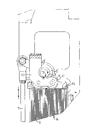
Fig. 2 is a side elevation of the mechanism of Fig. 1, parUy in section.
The Drawings show only those details essential to an understanding
of the present invention.
The infeed mechanism includes a shaft 1 extending through the
greater parl of the mechanism. The shaft 1 is oriented at right angles to a
maga7ine 14 holding flat-laid package blanks 10. At both ends 2 and 4, lhe
shaft 1 is journalled with a conventional bearing such as a ball bearing or
sliding bearing 3. At one end 4, the shaft 1 is moreover journalled so that it
may rotate in only one direction, with a so-ca71ed free-wheel hub 5 or
reverse stop. The free-wheel hub 5 is surrounded by a lever 6. This lever 6
is, in its turn, interconnected with a piston rod 7. The piston rod 7 is
displaceable with a reciprocating movement and is connected to a drive
unit, preferably a pneumatic piston and cylinder assembly 8. The drive unit

2~3:~2
may also consist of a hydraulic piston and cylinder assembly. In the
preferred embodiment, the lever ~ receives its movement via a piston rod 7,
but other solutions are also conceivable here, such as a cam.
The shalt 1 extending through the meehanism is urged against at
least one elastic belt ~ oriented in the longitudinal direction of ~he magazine
14. In Fig. 1, four such belts 9 are shown, but this number may of course be
varied, depending upon the length of the package bianks 10 which are to
be fed through the mechanism. The belt or belts 9 each interconnect at least
two wheels 11 anchored in a bracket 1~ for each belt 9. By employing two
l O wheels 11, a suitable pressure point 13 for the shaft 1 will be createdb~tween the wheels 11. In turn, the belts 9 are urged against the upper
edge of the package blanks 10. Naturally, a larger number of wheels 11
may be employed, but practical trials have demonstrated that, by employing
. two wheels 11, a reliable and even infeed of the package blanks 10 will be
l 5 obtained.
The elasticity of the belts 9 compensates for vari~tions in height uf the
package blanks 10. At the same time, the material (for example an elastic
rubber material) provides friction against the package blanks 10, which
contributes to a reliable infeed or advancement of the package blanks 10.
The operation of the mechanism according to the present invention is
described substantially with reference to Fig. 2 in which directional arrows
have been drawn.
When the pneumatic piston and eylinder assembly 8 causes the
piston rod 7 to execute its positive movement (+), this movement is
~5 transferred via the lever 6 to ths shaft 1. In such instance, the free-wheel
hub 5 locks and the linear movement of the piston rod 7 is converted into a
ciroular shaft movement. The shaft 1 prssses on a point 13 on the endless
elastic belt 9 and the circular sha~t movement is then transferred to the bel$
9 with its wheel 11, which thereupon feeds the package blank 10 forwardly.
~0 The belts 9 which are oriented in the longitudinal direction of themagazine 14 are urged against the upper edge of the package blanks 10.
The movement from the shaft 1 is transferred via the belts 9 and the wheels
11 to the package blanks 10 and th0y move forwardly in the longitudinal
direction of the magazine 14. In such instance, a package blank 10 reaches
~5 the gap 15. At this point, the package blank 10 is entrapped, rnoved up

2~79 L~2
through the gap 15 for further processing in the ~illing machine by righting of
the package blank, bottom sealing, fiiling and final sealing to torm a finished
package.
When the piston rod 7 executes its negative movement ~ he free-
5 wheel hub 5 will act as a s~andard ball bearing in respect of the lever 6.Thus, no movement will be transferred from the negative rnovement of the
piston rod 7 to the shaft 1. Hence, the negative movernent of ~he piston rod
7 does not give rise to any reciprocal or return movement which a~fects the
package blanks 10.
l O By making those holes in which the wheels 11 are secured in their
brackets 12 slightly oval, it is possible to impart to the wheels 11 a slight
springing action, which may be of advantage if the package blanks 10 are
loaded into the magazine so that their upper edge is not ev0n.
As will have been apparent from the above description, the present
l 5 invention will realize an infeed mechanism for flat-laid package blanks
which functions irrespective of the quality and method of loading of the
package blanks. The infeed mechanism gives an even and reliable forward
movement without any disruptive return strokes.
The present invention should not be considered as restricted to that
20 described above and shown on the Drawings, many modifications being
conceivable without departing from the spirit and scope of the appended
Claims.

Representative Drawing
A single figure which represents the drawing illustrating the invention.
Administrative Status

2024-08-01:As part of the Next Generation Patents (NGP) transition, the Canadian Patents Database (CPD) now contains a more detailed Event History, which replicates the Event Log of our new back-office solution.

Please note that "Inactive:" events refers to events no longer in use in our new back-office solution.

For a clearer understanding of the status of the application/patent presented on this page, the site Disclaimer , as well as the definitions for Patent , Event History , Maintenance Fee  and Payment History  should be consulted.

Event History

Description Date
Inactive: IPC from MCD 2006-03-11
Application Not Reinstated by Deadline 2002-09-25
Time Limit for Reversal Expired 2002-09-25
Deemed Abandoned - Failure to Respond to Maintenance Fee Notice 2001-09-25
Letter Sent 1999-09-15
Inactive: Application prosecuted on TS as of Log entry date 1999-09-15
Inactive: Status info is complete as of Log entry date 1999-09-15
Request for Examination Requirements Determined Compliant 1999-08-13
All Requirements for Examination Determined Compliant 1999-08-13
Application Published (Open to Public Inspection) 1993-04-03

Abandonment History

Abandonment Date Reason Reinstatement Date
2001-09-25

Maintenance Fee

The last payment was received on 2000-09-19

Note : If the full payment has not been received on or before the date indicated, a further fee may be required which may be one of the following

  • the reinstatement fee;
  • the late payment fee; or
  • additional fee to reverse deemed expiry.

Patent fees are adjusted on the 1st of January every year. The amounts above are the current amounts if received by December 31 of the current year.
Please refer to the CIPO Patent Fees web page to see all current fee amounts.

Fee History

Fee Type Anniversary Year Due Date Paid Date
MF (application, 5th anniv.) - standard 05 1997-09-25 1997-09-08
MF (application, 6th anniv.) - standard 06 1998-09-25 1998-09-04
Request for examination - standard 1999-08-13
MF (application, 7th anniv.) - standard 07 1999-09-27 1999-09-08
MF (application, 8th anniv.) - standard 08 2000-09-25 2000-09-19
Owners on Record

Note: Records showing the ownership history in alphabetical order.

Current Owners on Record
TETRA LAVAL HOLDINGS & FINANCE S.A.
Past Owners on Record
JONNY OLANDER
MAGNUS JANSON
Past Owners that do not appear in the "Owners on Record" listing will appear in other documentation within the application.
Documents

To view selected files, please enter reCAPTCHA code :


To view images, click a link in the Document Description column (Temporarily unavailable). To download the documents, select one or more checkboxes in the first column and then click the "Download Selected in PDF format (Zip Archive)" or the "Download Selected as Single PDF" button.

List of published and non-published patent-specific documents on the CPD .

If you have any difficulty accessing content, you can call the Client Service Centre at 1-866-997-1936 or send them an e-mail at CIPO Client Service Centre.

({010=All Documents, 020=As Filed, 030=As Open to Public Inspection, 040=At Issuance, 050=Examination, 060=Incoming Correspondence, 070=Miscellaneous, 080=Outgoing Correspondence, 090=Payment})


Document
Description 
Date
(yyyy-mm-dd) 
Number of pages   Size of Image (KB) 
Representative drawing 1999-03-14 1 16
Claims 1993-12-03 1 38
Abstract 1993-12-03 1 24
Drawings 1993-12-03 2 39
Description 1993-12-03 4 177
Reminder - Request for Examination 1999-05-25 1 118
Acknowledgement of Request for Examination 1999-09-14 1 193
Courtesy - Abandonment Letter (Maintenance Fee) 2001-10-22 1 183
Fees 1996-08-18 1 61
Fees 1995-08-15 1 70
Fees 1994-08-30 1 73