Note: Descriptions are shown in the official language in which they were submitted.
WO 91/15170 PCI'/SE91/00240
2079 5 ~
ARTI FICIAL TOGGLE JOINT
The present invention relates to an artificial knee-
S joint according to the preamble of Claim 1.
The gait of a thigh amputee is considerably different
to that of the gait of a normal healthy person, due to
the absence of important muscle ~r OU~. Because of the
loss of the knee muscles, the amputee can no longer
bend and then again actively stretch the knee-joint
under load. In the case of earlier knee-joint pros-
thesis using various types of braking mech~n;~ms, the
prevention of leg collapse in the su~u~Ling phase,
i.e. that period in which the foot is in contact with
the ground or like surface, has only been achieved with
a greater or lesser degree of security. Thus, differing
degrees of SU~Ol Ling-phase stability have been achiev-
ed. The prothestetic leg is fitted to the amputee with
the knee straight, and the knee then remains straight
during a major part of the ~ olLing phase. If the
knee-joint me~h~nism is very stable, it is not possible
to bend the knee until the supporting phase is ter-
minated. This impossibility of h~n~i ng the knee at the
beginning and the end of the supporting phase means
that the amputee must consume more energy when walking.
The absence of calf muscles also means that the gait of
the person wearing the prosthesis is more energy de-
manding than the gait of a normal person.
The present artificial knee-joint is constructed to
imitate the working mode of the human knee-joint, so
that the amputee is able to walk with a natural gait.
The knee-joint can be said to be a further development
of the existing quadruple-joint polycentric type of
'~C
WO91/15170 PCT/SE91/00~0
207~5~7
joint. By polycentric joint is meant here that the
rotational centre has different positions at different
knee-joint angles, i.e. there are several pivot cen-
tres. The human knee-joint is also polycentric. By
polycentrical quadruple-jointed knee is meant a knee in
which the thigh part and the lower-leg part are mutu-
ally joined by two linkage mech~n;sms, each being pivo-
tally connected at its respective ends to the thigh
part and the lower-leg part. This results in four pivot
points. Quadruple joint meçh~nisms are now the most
common joints available. However, in order to achieve
high su~ Ling phase stability, it is necessary to
supplement these mechAnisms with some form of mech~n;-
cal/hydraulic lock or brake device. The earlier known
tec-~nical solutions generally cause the knee-joint to
become highly complex and undesirably heavy.
Described and illustrated in U.S. Patent Specification
No. 2,638,605 is a knee-joint which comprises linkage
mech~n;sms in which locking is effected by means of a
catch with the knee straight, this catch being released
by means of a linkage mechanism which transmits move-
ment of the toe-part to the knee-joint. In addition to
being highly complicated, a serious drawback is that
the knee-joint is apparently too heavy for practical
use and results in an unnatural termination of a walk-
ing step.
The object of the present invention is to provide
an improved polycentric knee-joint which has high
su~o~Ling-phase stability, which is light in weight
and with which locking of the knee-joint is effected
automatically in a simple fashion as a result of the
construction and design of the knee-joint, and also to
eliminate the drawbacks encountered with earlier known
3 20795~7
techniques. The inventive kneejoint is a polycentric joint
and includes a linkage mechanism consisting of a plurality of
linkage arms of varying lengths which are mutually arranged
to achieve high supporting-phase stability and a simple,
automatic locking function. This locking function is effective
solely in an extended position and solely when load is
exerted on the heel. When the foot rolls over onto the
forward part, as the wearer of the prosthesis walks, the
locking mechanism is released automatically. This means
that the locking mechanism will not prevent natural
termination or completion of a walking step.
The invention will now be described in more detail with
reference to the accompanying drawings, in which:
1 5
Figure 1 illustrates schematically a preferred embodiment of
the invention;
Figure 2 illustrates different angular positions of the
embodiment shown in Figure 1 in a normal course of
movement;
Figure 3 illustrates another working method of the
embodiment illustrated in Figure 1, which allows different
angular positions with bending up to 180 degrees; and
Figure 4 illustrates the embodiment in a skiing, ice-skating or
dancing position.
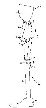
The knee-joint illustrated in Figures 1-4 comprises
linkage mechanisms which include two base link-arms and
seven pivot points. A thigh part C has two pivoted
r T A
WO91/1~170 PCT/SE91/00~0
20795~7 --
attachment points 1, 2 mounted on the underside of a
cup-shaped structure 3, which is intended to be secured
to the thigh in a conventional fashion. Two base arms
A, B extend respectively from the aforesaid attachment
ponts 1, 2 to attachment elements 4, 5 on the lower
leg.
A lower-leg part D is constructed around an elongated
part 6, which is constructed to carry an artificial
foot 7 at its lower end and to carry a first attach-
ment element 4 at its upper end. A second attachment
element 5 is mounted on the rear side of the elongated
part 6, preferably within the range of from one to
three-quarters of the length of the lower leg. These
attachment elements 4, 5 are intended to receive the
two base arms A, B extending from the cup-shaped part
3. The attachment elements 4, 5 can also be considered
as a form of moveable linkage mech~n;sms or rocker
means.
The first attachment element 4 mounted on the upper end
of the lower-leg part D can be described as a linkage
mech~nism having a slightly curved V-shape with three
pivot points 8, 9, 10, of which the pivot point 9 is
mounted or located between the other pivot points
and is connected to the elongated part 6 of the lower
leg. The first attachment element 4 functions as an
attachment means for the base arms A, B and also as a
balance-holding device whose movement is contingent on
the movement of the centre of gravity of the person's
~ody. The pivot point 9 is the point around which the
first attachment element moves. The base arms A, B,
which extend from the thigh part, are connected to the
two pivot points 8, 10. These two pivot points 8, 10,
together with the two pivot points 1, 2 at the thigh
WO91/1~170 PCT/SE91/~ ~0
2n79587
._
part at the ends of the first attachment element 4, can
be said to form the l'polycentric part" and the distance
of these pivot points from one another is configured
and dimensioned in accordance with the quadruple-pivot
polycentric joint type.
The other attachment element 5, which is mounted ap-
proximately centrally on the elongated part 6, can be
described as a linkage mechAn;sm, rocker means or
locking joint which has two pivot points 11, 12, of
which the first pivot point 11 is connected with the
elongated part 6 and the second pivot point 12 is
connected with the rear base-part B, which extends from
the thigh part C and has a curved extension on the rear
side of the lower-leg part D. Arranged in the region
around the second attachment element 5 is an adjustable
mechanical lock-stop device 13 which has approximately
the same longit~ n~l extension as the attachment
element S and which is removable from the lower-leg
part. The lock-stop device 13 is normally attached to
the front part of the elongated part 6 and limits the
movement of the attachment element 5. The lock-stop
device 13 is arranged in a manner to normally provide a
distinct limitation of the forward movement of the
attachment element 5 and is therefore manufactured from
a rigid material, preferably metal. In order to provide
a certain degree of resiliency or elasticity at the
movement limit position, the stop 13 may be made of a
metallic material which is covered with an elastic or
resilient material, or the stop and/or parts coacting
therewith may alternatively be made of a material which
provides a corresponding function.
The knee-joint functions in the following manner. When
load is exerted on the heel, in which case the knee-
WO91/1~170 PCT/SE91/00~0
6 20795~7
joint is substantially straight, the first attachment
element 4 will move clockwise around the pivot point 9
and force the second a-tachment element 5 to move
towards the lock-stop device 13. As long as weight is
exerted on the heel, it is impossible for the second
attachment element 5 to open and move clockwise, even
if considerable forces attempt to bend the joint. On
the contrary, the locking effect is amplified instead.
Because of the elasticity or resiliency of the lock-
stop device, the gait of the person wearing the prosth-
esis will be highly similar to the gait of a normal
person in setting the heel onto the ground, with subse-
quent locking of the knee-joint. When walking with the
knee locked, the attachment element 5 may also have a
given degree of resiliency against the lock-stop device
13, thereby enabling the joint to bend slightly in its
locked state, which also contributes to a more natural
gait.
When exerting load on the forward part of the foot, the
first attachment element 4 will rock over in an anti-
clockwise direction. Thus, when the knee-joint is
subjected to bending forces, the second attachment
element 5 is able to open freely and the leg is able to
swing quite freely. This takes place when it is natural
to terminate or complete a walking step.
The realization that a polycentric joint can be ad-
vantageously constructed with moveable attachment
elements 4, 5 on the lower leg 6 has made it possible
to construct the aforedescribed knee-joint with its
embodied locking function which will not prevent
termination of a walking step but will assist in enabl-
ing the transition between the locking positions and
the moveable positions of the knee-joint to take place
WO91/15170 PCT/SE91/00~0
20795~37
automatically.
Figure 2 illustrates a normal movemen- pattern of the
knee-joint and shows the knee-joint in three different
S positions. In the first position, the leg is shown
fully extended, whereas in the second position, the
knee-joint is in a half-bent position and, finally ,
pACsec to a fully-bent position corresponding to an
angle of approximately 150 degrees.
Figure 3 illustrates a movement pattern which includes
a bend of 180 degrees. In this case, the lock-stop
device is removed and the second attachment element 5
moves in an opposite direction compared with the normal
movement. The drawback with this movement pattern is
that when the knee-joint is in a half-bent position the
lower leg will be located more forwardly than in a
coLLes~ol,ding position with a normal movement pattern.
In turn, this results in a smaller lever-arm for the
thigh when walking upstairs and when cycling. This
state of the knee-joint is intended, however, for use
when wishing to fully bend the leg.
Figure 4 illustrates a state in which the lock-stop
device 13 is displaced from the position shown in the
earlier Figures. In this case, the leg can be swung
freely until the user places the heel on the ground and
the locking function therewith becomes operative. The
advantage afforded hereby is that the user is able to
participate in such activities as dancing and athletic
training.
The aforedescribed knee-joint is primarily constructed
for children and with view to their great need to be
mobile, although the knee-joint is, of course, also
WO91/15170 PCT/SE91/~ ~0
20795~7
well suited for adults. Because of its particular
construction, the knee-joint is well suited for manu-
facture from some form of composite material. It is
also stable and light in weight and has a wide angular
range within which the knee-joint can be bent. In a
normal case, the knee-joint can be bent through about
l50 degrees, and in the case of a special design can be
bent through about 180 degrees. It includes a simple,
automatic locking function which does not prevent
natural completion of a walking step and the locking
effect is fully geometrical, so that in principle,
there are no parts which can become worn. Furthermore,
the knee-joint is locked only in the extended position
of the joint and only when the heel of the foot is
subjected to load.
Sinae the described and illustrated embodiments of the
inventive knee-joint are meant solely to illustrate the
inventive concept, it will be understood that the
invention is not limited to these embodiments but can
embrace all knee-joints which lie within the scope of
the following Claims.