Note: Descriptions are shown in the official language in which they were submitted.
PCT/6B 9 1 / 0 0 5 6
o 5 ~une 1~
-1- OS u~ ~2
2G800D~1
SIGN~T DIST~TBUTION
The present invention relates to the distribution
of signals on a network and in particular to the
distribution of AM (amplitude modulated) television
signals.
Conventionally, television has been broadcast as AM
signals with different channels modulated onto
sub-carriers at different frequencies. Existing cable
television services using copper coaxial cable have
adopted corresponding analogue AM techniques to provide
channels in a region of the same UHF spectrum used for
broadcast television.
It is now proposed to use cable networks such as
fibre optic networks for the distribution of television
signals. The wide bandwidth offered by such networks
offers the possibility of upgrading to carry future
wideband services such as HDTV and the same network may
also be used for services other than television, such as
telephony. However whilst the use of AM techniques is
necessary if the television signals are to be received by
conventionally equipped television sets there are a number
of problems associated with the use economically of
AM techniques on optical networks. In particular the
carrying of AM optical signals requires less splitting in
order to allow a high power budget, and the use of highly
specified linear opto-electronic devices.
According to the present invention, a method of
distributing signals from a head-end station via a
network comprises combining a plurality of AM channels
modulated on sub-carriers at different frequencies to form
a composite analogue signal, and characterised by treating
the composite analogue signal to reduce the peak-to-mean
ratio, digitising the composite analogue signal,
transmitting resulting digital data onto the network,
receiving the
United Kin~dom P~tent Offic~ H T
PCT Inir ;.~fonaf App~cation SUBSTIT~TE S EE
W091/15927 - 2 - PCT/GB91/~K~
21~3~
digital data at a receiver and reconstituting the
composite analogue signal for reception at a termination.
Preferably the network is an optical network and the
receiver is an optical receiver. Preferably the
composite analogue signal is treated by clipping the
signal.
A preferred aspect of the present invention provides
a method of distributing, e.g., television signals which
is particularly well-adapted to use with optical networks
whilst at the same time maintaining compatibility with
conventional analogue television sets. As noted above,
television signals used for terrestrial broadcasting are
modulated onto sub-carriers at different frequencies.
When a composite signal is formed by adding together the
different channels the resulting waveform has a much
higher peak-to-mean ratio than the individual carriers.
It is therefore possible to clip or compress the maxima
and minima before quantising without significantly
degrading the performance. The A/D converter used for
digitising the signal can then operate over a more
restricted input amplitude range and so requires fewer
quantisation levels to achieve an adequate output video
signal-to-noise ratio.
Preferably the method includes receiving the
digitised signal at a node remote from the termination
and transmitting the reconstituted signal onwards for
reception at the termination.
The detection of the digital data is advantageously
carried out at a node such as a distribution box or
pedestal near the customer~s premises. The television
signals may then be deli~ered over conventional coaxial
cable in a st~n~rd format, avoiding the need for a
special adapter or other equipment at the customer-end.
PS~ / 0 0 5 C 8
o ~ JU~e 19~
05 u~ 92
~3- 20&00~1
Preferably the composite analogue signal has a
bandwidth of one octave or less and is digitised by
sampling at a sampling rate below the Nyquist rate.
Preferably, in addition to or as an alternative to
clipping the composite analogue signal the method further
comprises compressing the composite analogue signal at the
head-end station and applying complementary expansion at
the receiver.
Companding may be carried out either in the
analogue or in the digital domain and preferably the
compression function is the cumulative distribution
function of the Gaussian probability distribution
function.
According to a further aspect of the present
invention there is provided a system for distributing r
signals comprising a head-end station, one or more
receivers, and a network connecting the head-end station
to the or each receiver, and characterised by the head-end
station including an input stage arranged to receive a
composite analogue signal comprising a plurality of AM
channels modulated on sub-carriers at different
frequencies, converter means arranged to treat the
composite analogue signal to reduce the peak-to-mean ratio
and to digitise the composite analogue signal, and
transmitter means arranged to transmit the resulting
digital data onto the network, the receiver including
reconstituting means arranged to reconstitute the
composite analogue signal and output means arranged to
output the composite analogue signal for reception by a
termi nati on.
A method and system in accordance with the present
invention will now be described in further detail with
reference to the accompanying drawings, in which:
Figure 1 is a block diagram showing a distribution
system;
Figure 2 is a block diagram showing a signal path
in greater detail;
~ ! Init~ ~ D~ C;~_ I _
WO91/t5927 - 4 - PCT/GB91/00568
2~0~21
Figure 3 is a diagram showing an alternative
arrangement for the multiplexer of Figure 2; and
Figures 4a - 4d are diagrams showing sub-carriers
and a composite signal.
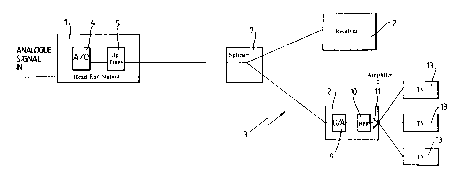
A system for distributing television signals via an
optical fibre network comprises a head-end station l and
a number of optical receivers 2 connected to the head-end
station l via a fibre network 3. In the present example
the fibre network 3 is a passive optical network using a
star topology but the present invention is equally
applicable to other fibre optic networks using different
topologies.-
The head-end station l receives at its input a
composite analogue signal which in the present example
covers the spectrum from 470-860 MHz. This input signal
comprises sub-carriers at different frequencies
amplitude-modulated with different television signals.
These signals are input to an A/D converter 4 which, as
described in further detail below, clips and digitises
the signal. An optical transmitter 5 modulates an
optical signal with the digital data output by the A/D
converter and outputs the signal onto the fibre network
3. The signal pas 8 es through different stages of the
fibre network 3, including one or more passive optical
splitters 7 and is received by the optical receivers 2.
For clarity only two optical receivers 2 are shown in
Figure l, but in practice many more may be connected to
each network. At the receivers 2 which may, for example,
be positioned in street cabinets, the composite optical
signal is reconstituted from the optical data and output
as an analogue signal via coaxial cables 8 to
conventional television sets 13.
The signal path from the head-end station l to the
television set is shown in greater detail in Figure 2.
Data is output from the A/D converter 4 in parallel as
WO91/15927 - 5 - PCT/GB91/00568
20800'Q1
8-bit words. An 8:l multiplexer 8 converts the output
from the A/D converter 4 to a serial bit stream. This
bit stream is used to modulate the output from the
optical transmitter 5 using conventional techniques. The
operation of the multiplexer 8 is locked to a 7 GHz clock
generated locally in the head-end station. This clock
signal is divided by eight to provide a lower rate clock
for the A/D converter 4. In transmission over the fibre
network 3 the signal output by the transmitter 5 may be
split up to 49 ways, within the constraints of the power
budget in the present example. At the receiver 2 a l:8
demultiplexer 12 assembles 8-bit parallel words from the
serial datastream and outputs those 8-bit words to a D/A
converter 9. The output from the D/A converter 9 passes
through a band pass filter lO and via an output amplifier
stage ll to up to 20 different television sets 13
connected to the receiver 2 by conventional coaxial
cables.
The system may be used to distribute signals to
so-called "cable ready" sets. Such sets typically have a
VHF baseband input up to 450 MHz. For such systems use
can be made of aliasing channels present in the lower
frequency range. These are channels at frequencies below
those of the original components of the composite
analogue signal which are generated as a result of
sampling below the Nyquist rate. In this case the
reconstituting filter lO is a low-pass filter rather than
a band-pass filter. The low frequency channels output
from the reconstituting filter are inverted unless the
input to the A/D converter is first inverted.
Figures 4a - 4d, show schematically the formation of
the composite analogue signal from three carriers
cl,c2,c3. The carriers have amplitudes
Pl,P2,P3 respectively. The mean (rms) level of
each carrier is then pn/(2~2). The different component
carriers add
~,
-
W~91/15927 - 6 - PCT/GB91/~568
~$~
together to form the composite signal shown in Figure
4d. It can be shown that the amplitude of the composite
signal, when it comprises n channels, each of amplitude p
is np and its~mean level is ~n(p/2~2). The
peak-to-mean ratio of the composite signal is therefore
far greater than that of the individual sub-carriers. At
the input to the A/D converter relatively severe clipping
may be applied to limit the dynamic range of the signal
prior to quantisation making it possible to minimise the
number of quantisation levels without significant loss in
the quality of the signal. Clipping may be applied using
an appropriate clipping stage before the A/D converter.
Alternatively if that converter has suitable clipping
characteristics clipping may be achieved by overloading
it by a suitable margin.
The composite analogue signal is limited in
bandwidth to less than one octave. Not only does this
serve to reduce second order intermodulation distortion
but it makes possible sampling at a rate below the
Nyguist minimum, that is twice the frequency of the
maximum frequency component of the signal. Sampling
below the Nyquist rate causes aliasing distortion. When
however the signal is confined to less than one octave
and sampled at a rate only slightly greater than the
maximum frequency component the aliasing distortion falls
in the unused frequency band below the signal octave
band. The aliasing distortion therefore does not
compromise the performance of the system and the bit rate
of the system is only one half that needed for full
Nyquist sampling. As noted above, when generating
signals for cable-ready VHF TV sets the production of low
frequency aliasing channels may be used to shift the
received channels into the desired frequency range.
The A/D converter 4 defines a number of amplitude
bands and determine6 which amplitude band matches the
~:$
~O91/15927 PCT/GB91/005~
2080021
sample value. Each amplitude band is represented by a
binary word and a byte is output accordingly. The
resultant bit rate when these bytes are converted to a
serial stream by the 8:l multiplexer 8, is the product of
the sampling rate and the number of digits in a byte.
Clipping minimises the number of quantisation levels
required and so enables a reduction in the byte size and
bit rate.
Optionally compression may be applied to the signal
before or after it is sampled by the A/D converter 4.
Known A/D converters for video signals use linear
quantising with one output byte representing one
quantisation level. The present system however by
applying compression to the composite analogue signal as
it is digitised reduces the number of possible output
words required for a given output video quality by a
factor of two or more, giving a further saving in the bit
rate. The preferred compression function is the
cumulative distribution function of the Gaussian
probability distribution function (PDF). If the input
waveform to the compressor has a Gaussian PDF, the output
PDF from the compressor is uniform with output in the
range 0 to l. This uniform PDF can then be quantised
linearly and each output codeword is then equi-probable.
The compressor and matching expander at the receiver may
be realised in hardware using a network of d~odes and
resistors, or in software using a look-up table following
a suitable linear A/D converter.
The digital circuits in the head-end station l and
the receiver 2 are synchronised using word alignment
techniques. For example, the least significant bit in
each word may be identified by a periodic function such
as a Barker code by regular bit stealing. This sequence
is then detected using a suitable sampler, logic function
WO91/15927 - 8 - PCT/GB91/005~
2080021
and clock slip circuit. Preferably the clock operates at
the word rate rather than the serialised bit rate.
In an alternative arrangement shown in Figure 3 two
8:l multiplexers are used in parallel at a lower clock
rate of l. 2 GHz. In this case a pair of A/D converters
are used, operating at a clock rate one eighth of that of
the multiplexers.
Although the embodiment discussed above relates to
the distribution of television signals, the invention, in
its broadest aspects, is applicable to other signals such
as, e.g., audio signals.