Note: Descriptions are shown in the official language in which they were submitted.
DEVICE AND METHOD FOR IDENTIFYING AND
QUANTIFYING LAYERED SUBSTANCES
Field of Invention
This invention relates to a device and method for the non-intrusive and
spatial interrogation of substances to identify and quantify the substances
from
measurements dictated by the dielectric profile of the substances. In
particular, this
invention relates to a device and method of detecting an accumulation of air,
water, ice,
snow or variety of possible contaminants such as de-icing fluid on aircraft
surfaces.
Back;~round of Invention
Ice accumulation on aircraft surfaces has been a problem since the
inception of the aviation industry. The accumulation of ice has four main
effects which
are all negative and in some instances catastrophic. First, aerodynamic
performance is
severely restricted resulting in a loss of lift and increase drag. Second, the
accumulation
of ice increases the aircraft weight. Third, the accumulation of ice will
impair or restrict
the movement of control surfaces. Fourth, the ice may be ingested into the
engine or
other system intakes terminating engine operation.
Recently, interest in aircraft icing has been greatly heightened with an
increase in industry and public awareness of the hazards associated with this
problem.
Although the detrimental effects of ice build up on aircraft performance has
been
generally well acknowledged, difficulties in predicting or measuring ice
accumulation on
aircraft has prevented rigorous and reliable procedures for flight crews both
on the
ground and in the air to minimize this problem.
The problem of aircraft icing occurs in two broad categories. First, inflight
icing occurs on the leading edge of the airfoil. This type of ice build up is
common and
is handled by pilot observations or pilot awareness or suspicions of impending
icing
conditions. In many aircraft, the leading edges of the wing are heated by
engine bleed
air at temperatures of up to 250°C. Engine air bleed is normally done
at regular
intervals when icing conditions are likely regardless as to whether any ice
has
accumulated. A percentage of engine air is required to be used to heat the
aircraft wing
rather than for propulsion purposes. It is very inefficient to bleed engine
air when no
ice has accumulated on the aircraft surface.
The second category of aircraft icing is ground icing. Ground icing occurs
over the top of the aircraft surface when the aircraft is standing. Icing on
the leading
10% of the wing has the most critical aerodynamic effect. This type of ice
accumulation
2Q~~t~67
-2-
is handled by the application of de-icing or anti-icing fluids. The problem is
amplified
since de-icing depends not only on how well the de-icing was undertaken but
also
whether ice has re-accumulated since de-icing.
On current commercial aircraft, pilots have no reliable way of judging the
amount of ice accumulated on the surface of the aircraft both inflight and on
the
ground. Further, pilots have no means of assessing the status of the de-icing
or anti
icing fluids which may have been applied in accordance with current flight
procedures.
Pilots are accordingly faced with difficult decisions on a regular basis in
order to
maintain flight schedules.
Several devices have been proposed which are designed to detect the
presence of ice which has accumulated on the aircraft surface. One such device
will
vibrate an aircraft surface at a known frequency. When the aircraft surface
vibrates at
a different frequency, the presence of ice has been detected.
Still other devices have been proposed which detect the presence and
thickness of ice on an aircraft surface. Such devices have been described in
detail in
United States Patent No. 4,766,369, Weinstein. This device uses two capacitive
gauges
and a temperature gauge. The ratio of the voltages of sense side of the
capacitive
gauges determines the thickness of the ice present.
Although, these devices may detect the presence of ice on an aircraft
surface it cannot detect the presence of substances other than ice such as
snow, slush,
de-icing fluid or dirt. In fact, there are no known devices which can detect
the presence
of snow on an aircraft surface.
Devices and analytical techniques exist for non-intrusive interrogation of
materials to deduce their physical properties. Dielectric sensors and
analytical
techniques measure the spatial profile of permittivity of a material by
multiple
wavelength interrogation. A spatially periodic field is imposed upon the
material via a
first electrode under the control of a wavelength controller. A second or
sense electrode
is then used to measure the effect of the material on the charge induced by
the first
electrode in response to the periodic field. By varying the wavelength,
spatial
distribution of complex permittivity is deduced as a function of the temporal
frequency.
The physical properties of the material can then be deduced.
Such devices are used to monitor material changes such as the outgassing
208~1~6'~
-3-
of solvents from paints, the removal of moisture from coatings, the diffusion
of dopants
into semi-conductors and the deposition of materials. Such devices and
techniques are
more fully described in United States Patent No. 4,814,690, Melcher, et al.
and United
States Patent No. 5,015,951, Melcher.
Initially, it was believed that such devices and techniques wauld be useful
in the detection of ice accumulation on an aircraft surface. However when
attempts
were made using such sensors to detect accumulation of ice on aircraft
surfaces, the
analytical techniques of Melcher, et al. were found to be highly unstable and
could not
in real time accurately and reliably detect, identify and measure the
thickness of the
various contaminants accumulating on the aircraft surface.
One of the problems of the approach of Melcher et al. is that the electric
potential along a planar electrode array must be sufficiently defined and
known at all
times. The electric potential is required so that the theoretical models can
be used to
predict the spatial permittivity profile of the measured substance. However,
the electric
potential varies depending on the electrical properties of the substance being
measured.
Since the various substances which can accumulate on the aircraft surface are
not known
beforehand, Melcher et al., was unsuitable for use as a substance detector.
Melcher also requires sampling to be of a laboratory-quality so that the
non-analyticity problems such as irregularity of the surface and complex
structures could
be avoided. Even with approximations, real time data processing was not
possible. Data
analysis using Melcher's techniques is normally in the order of hours.
Dielectric sensors measure the effects that the interrogated substance has
on the capacitance of the imposed field. The problems of air gaps on
dielectric sensors
are well known (see United States Patent No. 5,045,798, Hendrick and United
States
Patent No. 5,095,278, Hendrick). Air gaps severely limit the sensors' ability
to measure
the dielectric properties since air and a vacuum have the lowest theoretically
possible
permittivity. Further, air also induces noise into the capacitance
measurement.
Summary of Invention
It is therefore desirable to provide a device and method for conducting
non-intrusive interrogations of substances to identify and quantify across a
spatial profile,
a wide range of substances in real time.
It is further desirable to provide an electrode configuration to define
208006
-4-
potential fields to provide spatial measurements by spatially varying an
interrogation
signal and analyzing the attenuated response thereby identifying and
quantifying in real
time the layered substances causing such attenuation.
In one aspect of the invention, there is provided an electrode structure
S which is formed by a plurality of concentric electrodes and a potential
field shaper which
can be implemented by electronic switches to apply a plurality of discreet
voltage
patterns to each electrode to define a potential field and current
measurements are
taken from one of the electrodes. The measurements are analyzed in real-time
to
identify and quantify the substances overlying the electrode.
In a further aspect of the invention, there is provided an electrode
structure which is formed by a plurality of concentric electrodes and a
potential field
shaper which applies a discreet voltage to the electrode to define a potential
field and
the current measurements are taken from predetermined electrodes. The
measurements
are analyzed in real time to identify and quantify the substances overlying
the electrode.
In a further aspect of the invention, the electrode structure can be formed
by a plurality of concentric electrodes and the implied field is fixed and the
measurement of the signal can be taken from different electrodes.
In a further aspect of the invention, an apparatus for identifying and
208000
-s-
comprising at least seven dimensional regions defined by three complex
measurements
of impedance and temperature, and
computer means for storing a map means comprising a partition of a
vector space of predetermined characteristics of substances into regions of
profiles
s corresponding to the substances which could be overlying the surface, said
computer
means for correlating the measurement set with the map means thereby
identifying and
quantifying the substances overlying the surface and for generating an output
signal
corresponding to the identity and quantity of substances overlying the
surface, and
display means responsive to the output signal for displaying the identity
and quantity of substances overlying the surface.
In stilt yet another aspect of the invention, a second computer means
stores a database comprising sample data of sample measurements of the
probable
substances and quantities thereof together with estimates of corresponding
profiles of
the sample data and theoretical data of the probable substances and quantities
thereof
is together with corresponding profiles of the theoretical data, the second
computer means
remote from said first computer means, the map means is generated by a second
computer means by
(a) selecting the probable substances which are likely to be overlying
the surface,
(b) selecting data from the database corresponding to the probable
substances,
(c) successively dividing the selected data into subsets until each subset
satisfies a predetermined criteria for subdividing;
(d) defining a set of boundary functions, each of which describe a . . .
2s hierarchial boundary between the subsets;
(e) defining a set of profile functions, each of which describe the
distribution of the data in each subset; and
(f) collecting the sets of boundary and profile functions in a map
means.
In 'still yet another aspect of the invention, the computer correlates the
measurement set with the generated map means by
(a) defining a local profile by applying the measurement set to the map
2D8a~6~
-6-
means,
(b) refining the local distribution by numerical dithering of the
measurement set,
(c) calculating the variation of the refined local distribution,
(d) comparing the variation with a predetermined limit and if the
variation is greater than a predetermined limit, sending the output signal
that the
substance has not been identified and if the variation is less than or equal
to the
predetermined limit sending the output signal corresponding to the identity
and quantity
of the substances detected.
In still yet another aspect of the invention, there is provided a method for
identifying and measuring substances overlying a surface using a plurality of
concentric
electrodes underlying a surface, an electrode control means connected to the
plurality
of electrodes for defining an electric field at the surface, an amplitude and
phase
measurement means connected to the plurality of electrodes and electrode
control
means for measuring the currents responsive to the electric field, computer
means for
storing a map means comprising a partition of a vector space of predetermined
characteristics of substances into regions of profiles, and a display means
responsive to
an output signal for displaying the identity and quantity of substances
overlying the
surface. The method comprising the steps of:
(a) applying an electric field at the surface,
(b) measuring currents responsive to the electric field,
(c) converting the currents to a measurement set, and
(d) defining a local profile by applying the measurement set to the map
means,
(e) refining the local distribution by numerical dithering of the
measurement set,
(f) calculating the variation of the refined local distribution,
(g) comparing the variation with a predetermined limit and if the
variation is greater than a predetermined limit, sending the output signal
that the
substance has not been identified and if the variation is less than or equal
to the
predetermined limit sending the output signal corresponding to the identity
and quantity
of the substances detected;
2080067
_~_
(h) generating an output signal corresponding to the identity and
quantity of substances overlying the surface; and
(i) after a fixed period of time, repeating the process.
According to yet another aspect of the invention, a method of generating
a map is provided by
(a) selecting the probable substances which are likely to be overlying
the surface,
(b) selecting data from a database corresponding to the probable
substances, said database comprises sample data of sample measurements of the
probable substances and quantities thereof together with estimates of
corresponding
profiles of the sample data and theoretical data of the probable substances
and
quantities thereof together with corresponding profiles of the theoretical
data,
(c) successively dividing the selected data into subsets defining a set of
boundary functions describing hierarchial boundaries between the subsets, the
subsets
being divided until each subset satisfies a predetermined criteria for
subdividing,
(d) defining a set of profile functions describing the distribution of the
data in each subset;
(e) collecting the set of boundary and profile functions in a map. , , .
Detailed Description of the Drawings
In drawings which illustrate embodiments of the invention,
Figure 1 is a block diagram of the preferred embodiment of the
invention,
Figure 2 is a top plan view of the sensor head of embodiment of
Figure 1;
Figure 3 is a side elevational view of the sensor head of Figure 2;
Figure 4 is an exploded view of the sensor head of Figure 2;
Figure S is partial side sectional view of the sensor head of Figure 2
along the lines 5-S;
Figure 6 is a block diagram of the embodiment of Figure I,
illustrating an electrode structure of concentric rings; .
Figure 7 is a block diagram of the software routine of the
embodiment of Figure 1;
;..
208067
_s_
Figure 8 are the applied voltage patterns of the embodiment of
Figure 1;
Figure 9 is an illustration of alternate electrode configurations which
may used in the embodiment of Figure 1; and
Figure 10 is a block diagram of a second embodiment of Figure 1,
illustrating an electrode structure of concentric rings.
Detailed Description of the Invention
The underlying physics governing the functional performance of the device
of the present invention are based on the electroquasistatic subset of
Maxwell's
equations:
0 , al~.i = pi
9x~=0
D ~ aE! + ~p~ = 0
where the variables are defined as follows:
electric field intensity
p~ free charge density
a absolute permittivity
a conductivity
For purposes of illustration, the material under study is approximated by
horizontal layers (parallel to the sensor) in which the electrical properties
are constant,
and that all primed quantities vary as e'~' (where j is the square root of -1,
r~ is the
angular frequency of excitation, and t is the time) allows the reduction of
the above
system to the determination of a Laplacian potential, ~, within any given
layer to the
r scalar equation:
i .
p.
2~~Ofl6~
~~ = o
where
-~~ =E
At a boundary between layers the following jump conditions hold:
II ~ II = 0
Il~. a~ ll = o
where a = e- Q/j cv and n is the unit vector normal to the potential.
For a cylindrically concentric electrode embodiment the problem is
S cylindrically symmetric normal to the sensor surface. 'The potential
function is
decomposed into the natural eigenfunctions:
~~~~~z) _ ~ $m~Z)Jo(~,mr)
m
where Jo(.1",ro) = 0, J; is the ith $essel function, z is the coordinate
normal to the sensor
surface, r is the radial distance from the original, and ro is chosen large
enough so that
the potential is essentially zero beyond it.
These equations are then solved to yield an expression for the ideal charge
density, and hence the current, on the surface of the electrode. This is only
an
approximate solution as the electric potential between the electrodes has not
been
specified.
For a structure consisting of k finite layers bounded away from the sensor , .
by an infinite uniform material (i.e. the atmosphere), the current on an
electrode of
inner and outer radii r, and r2 respectively is given by:
I = 2njwet ~ (~m(O)Lm,n(r2J1(e1m rt) - riJt(~,mrl)) ~
m
where for ra < k + 1 we have:
CA 02080067 2000-07-07
-10-
Lm,n = -coth (~.~,0~ + 1
Slnh (/~,m0a2 (COth(~mOn) - E n~1 Lm "+1
E-n
while Lm,k+~ _ -1 and On is the thickness of the nth layer.
The actual measurements are made in the form of impedances, or equivalently,
as admittances (the reciprocal of impedance). The model must also account for
the contribution
to the total admittance of each pattern made by the fields generated by the
support electronics.
Because this contribution is independent of the material above the sensor, the
total admittance
can be written as:
Atotal = 1 + A strays
P
where P is the potential on the sensing electrode and A g,~ys is the
contribution from the
support electronics.
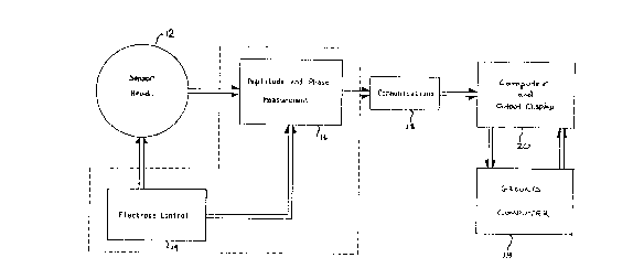
The device of the present invention is schematically illustrated in Figure 1.
The
invention generally comprises a sensor head 12, electrode control 14,
amplitude and phase
measurement system 16, communications systems 18 and computer and output
display system
20. Preferably, computer 20 is at least a computer having an INTEL~ 286 or
equivalent
processor using standard RS232 connections and the display is a conventional
monitor.
Refernng to Figures 2 and 3, sensor head 12 of the preferred embodiment has
a circular outline in plan view and a slim profile. Extending below the sensor
head 12 is a
plurality of connector pins 22.
The construction of sensor head 12 is illustrated in detail in Figures 4 and
5. The
sensor head has a protective layer 24 on the top surface. Immediately below
the protective layer
24 is electrode layer 25 having imbedded therein electrodes 26. Below the
electrode layer 25
is backing layer 28. On the bottom surface is a ground plane layer 30. A
temperature sensor
or thermistor 29 is embedded in backing layer 28. Thermistor 29 is
electrically connected to
a pair of connector pins for external connection. Thermistor 29 allows
temperature
measurements to be taken.
Protective layer 24 and backing layer 28 are preferably made of beryllium
200067
-11-
oxide. Beryllium oxide has a high thermal conductivity which is similar to
aluminum and
is electrically insensitive to temperature. Other materials could be used
provided such
material has good thermal conductivity, is electrically insulating and is
electrically
insensitive from at least -55 to 86°C but preferably between -65 to
100°C.
S The electrodes 26 are embedded in electrode layer 25 in an epoxy or a
glass substance 32. A plurality of bores 34 extend axially through backing
layer 28. In
the preferred embodiment, the configuration of electrodes 26 is a plurality of
concentric
circular electrodes.
As noted in detail later, this configuration can be represented in cylindrical
coordinates and the resulting voltage pattern can then be transformed
mathematically
by a Bessel series. The cylindrical configuration allows the voltage pattern
to be
represented in one dimension because the voltage level along the electrode
plane is
independent of angular position and only dependent on the radial position from
the
centre.
The number and width of the electrodes and the radial separation are
governed by the maximum allowable size of the sensor, the maximum accretion
thickness that must be detected, and the required sensitivity and accuracy of
the
measurements.
The penetration depth of the electric field from the sensor depends on the
"~ 20 distribution of spatial wavelength information at the electrodes.
Different electrode
configurations can be obtained to concentrate measurement sensitivity at
desired depths
in the substance being sensed. The sensitivity of a given configuration can be
optimized
,,
by selecting a configuration that will maximize the energy from the desired
spatial
component. A great number of electrodes will facilitate increased flexibility
in the
selection of optimum configurations.
Connector pins 22 extend through the bores 34 and are in electrical
contact with the electrode rings 26. Ground plane layer 30 has a plurality of
openings
31 allowing connector pins 22 to be insulated from contact therewith.
In the preferred embodiment, the outermost ring of electrodes 26 is
grounded. The inside surface of the outermost of bores 34 has a metallized
surface 36.
The outermost of connector pins 22 is brazed to the metallized surface 36 to
form a
hermetic joint 38.
.:.-, : ... .._'-~... '..'~ ~' ' .";~'.~ ,;:..:,..".. ';..!f ' ...~;r -
,,.;'.z, ~' ~..., ,..:. . :.:'!,::'.,..~~..,... . . ~ .
_ u.:
~y, ~,; .. ~..;,.' :.w'. ., ~ . ';.. ' ' .. ' ,..;.:.,~'G.. ~,. ,~...'.. ."~
.'.. ;:..,: .. . .~ ~.._:.:~..~ . ~; ...' ;...' .
a .,,,,._,-- , :.r.~....~ .~~.,.. ..,,.,. .._. ' ......,. .. . ;:~ ~.~.;.',,
;y ;......:, ~. .., . ,, .;; ...;~, ,.,;.':, ...._:
,.r'..r . ~ ~'~ ~ . ~a ... .;i~~.' ~ .. ,
W w .':F
.S. :.~.hlS. a -'. ..-~t. . ,. , , .
'2 ..' ~. . ,~;, ,r ~ fpY..,.. .. . ,... ; : ', ': "~; ,'~. ,.,;~~.~, ,.
':,..' ; ' ' . ' ..,:. ' ' , :. . .~.. . . .
S, ; y ~. ~,:
fi . . ~~~~ :'.' ~ . . i ~ ..' ~. ~~ . ' , , , .,',,'. ,.,'v . . .i, ' , ,~~ .
. , :.1, ~~ . ';: ...
r
Y . . .y .. . .. . ; ::.~ ' ~~.:- ,..,~,. y 4~,~~.'~'. ~ . .: ,~, ..
> . : y
.> '~.' '~.., : ,.., .,... .; ~ ~ . .,.
..n ~.. ,. . ,., ., . , ~ . ~. .. .. . . n.. .. . : ., ... ~ : v
r ... ..., ,.. .. . .,. .. .. . , . . .. . . ,n . . ,. ,.
.208006
- 12-
As illustrated schematically in Figure 1, sensor head 12 is electrically
connected through connector pins 22 to electrode control 14 and amplitude and
phase
measurement system 16.
Electrode control 14 is schematically illustrated in Figure 6. Electrode
control 14 comprises a signal source 50 connected to a multiple voltage
generator 52.
The multiple voltage generator feeds a signal selector 54. A digital pattern
control 56
also feeds the signal selector 54 to determine the voltage that is applied to
each
electrode. Each of the outputs of the signal selector 54 are connected in
parallel to
each ring of the electrodes 26, with the exception of ring e. Ring a is fed
directly from
sense circuit 58. Signal selector 54 also feeds sense circuit 58 which in turn
feeds ring
e.
The amplitude and phase measurement system 16 comprises a sense
circuit 58, a vector voltage measurement circuit 60 and digitization 61. Sense
circuit 58
is responsive to signal selector 54 and applies both the input voltage to ring
a and
monitors the resulting current in ring e. Sense circuit 58 will output two
signals which
.,
:,
are representations of the applied voltage and the resulting current. The two
signals are
fed to the vector voltage measurement circuit 60 that ~produces voltage levels
which
;i
correspond to the magnitudes and relative phase of the two signals.
Digitization 61
digitizes the two signals into a digital format and delivers the digitized
signals to
communications system 18.
The communications system 18 comprises a digital measurement control
circuit 62 which is a microprocessor based control. The digital measurement
control 62
controls the pattern generation and measurement sequences. It also controls
the
calibration and monitoring routines and formats the data for outputting to the
computer
20.
The circuits illustrated in Figures 6 and 10 are known standard electronic
circuits. The circuits are electrically connected in a conventional manner to
achieve the
desired results:
The electrode control 14 can operate in one of two ways. Both ways
provide equally satisfactory results. Referring to Figure 6, the electrode
control 14 could
f successively apply several discrete voltage patterns to the electrodes 26 to
define a series
of potential fields. Only one designated electrode of electrodes 26 is used to
measure
:'~ . ;::. r-'.: ' :v . ~r , .: :;:.. :: ; .; , ,.,, . ;;
t . ~..,. . ,: y',; : .. :. ': "; ~ .:.,;. :' . ~... : ; ' :=~ ,~. . ~.. : "
,:,.,' ,.~; .:,: . .'°. :.;
, ., .. :~., ~ ~ : : :,,:. , ,...
.. ' , ' .. . ~ :. . N .~ ~: . .. . . ., . . .. , , . . , '. -,', ~,. . , -;;
~ ' ; ; , : .
. : ~.. . . "..'.. ~ : ~~' ~ . . . .,.. , . .,
~ . 5 :. : , ~ .
:..:.::. ,.:..,.: ~ ~.v'~ .'..,. .::.:: r ..i:.:' ~'. ~.~' :~,. .~ -.~
'...:.,~. :~~..~..~.~.~~. ..i .,....., ";., . ;:.",
Il .: .; . .., ~.' ':,.,. ..:.: . . . . . .: ,. , ~-, ~, . .. ;'~ , ',"~. :
~., ' ., ~:. ' :'. ~. :., . , .~.~ .. . ' '
' I ', , .. ,. .: .::~ , :.~ . ~..; .... , ~ " ;. . ~ .. . ~ ,
13
the resulting currents. Alternatively, as illustrated in Figure 10, the
electrode control 14
could be fixed and apply only one discrete voltage pattern. The measurements
are
taken from alternately switched electrodes. In either case, a resulting series
of currents
from the sensor head 12 is obtained.
The discrete voltage patterns or electrode configuration can be specialized
to sense material at specific layer thicknesses. For example, the measurement
obtained
by one voltage pattern or electrode configuration could be most sensitive to
material
within a 1 mm thickness while other configuration is sensitive to layer
thicknesses of up
to 5 mm.
In the preferred embodiment, the voltage patterns represent Bessel
functions. Three distinct patterns as illustrated in Figure 8 can be used.
Each discreet
voltage pattern vary sinusoidally with time at a fixed magnitude and phase.
For
.:i
detection of substances which are likely to be found on an aircraft surface, a
sinusoidal
,;
frequency of 1 MHz has been found to be suitable. The three patterns differ in
the '.
.1
initial period and the rate of decrease in period.
Each configuration creates an electric field that produces a current in the
i
electrodes. The magnitude and phase of this current depends on the electrical
.i
' characteristics arid the thickness of the substance present on the sensor
surface. The
sensitivity of each configuration to the material being measured decays
exponentially as
a function of its depth. Each measurement configuration has a different rate
of decay
that is characterized spectrally by its dominant spatial wavelength such that
the degree
of penetration is intentional and unique to each.
Referring to Figure 6, sensor head 12 is schematically illustrated having
a plurality of concentric electrode rings 26 a-p. Each ring is electrically
connected to
I 25 the electrode control 14. Ring a is electrically connected to the
amplitude and phase
y measurement system 16. The electrode control 14 applies a voltage pattern to
each of
the concentric electrode rings. The amplitude and phase measurement system 18
will
measure the responsive current from a designated one of the concentric
electrodes 26,
,, ring e.
The electrode control 14 establishes and switches between each
configuration of Figure 8. Sense circuit 58 measures the three resultant
currents
innposed in the designated one of the electrodes 26, rin e. Each of the
resultant
g .
t :: ~ v . . . .
1
1
. , ( ~ TyS~ ~ , '. . ~ i '~ '.~ ~ '~ , ,. .,
~ ~,
i t ~ 5 .~. . , . i
;. ~. ..: ' :'.:' ..~;,': .;.~. ... ~~. ~:.~., ._. : .~. - .. .~.' .:!'~ ..
~..~.'~.. :av:~ ~~~' , ~.:. ,:;; .' . .~ .
t,
5
r.
-14- 2080067
currents is successively digitized to form six data inputs. A temperature
measurement
is taken from thermistor 29 and the seven pieces of data will form a
measurement set.
The measurement set is transferred from the amplitude and phase measurement
system
16 to the communications system 18 to the computer 20 for processing using the
inversion software.
Communications system 18 can be any suitable form of data transmission.
The resultant current received from the amplitude and phase measurement 16 is
in an
analog format. Communications system 18 can either transmit the data in an
analog
format and convert to a digital format prior to final transmission to the
computer 20.
Preferably, the data is converted immediately into digital and transmitted in
a digital
format to computer 20.
For use as an substance detector, the sensor head 12 is installed in a wing
or tail surface of an aircraft. The remaining hardware of the system can be
installed in
the main body of the aircraft with electrical connections extending between
the sensor
head and hardware. The display can be mounted in the cockpit for easy review
by the :
pilot or other flight officer.
The sensor head should be placed on the leading 10% of the wing or tail
surface. This will allow the sensor to detect inflight icing, yet will be
sufficiently level
for accurate ground ice monitoring. In most commercial aircraft this will
permit the
installation of the sensor head 12 behind the bleed air heated region and in
front of the
fuel tank. At this point, the curvature of the wing is sufficiently small to
allow the
sensor head 12 to have a 60 mm diameter to fit inconspicuously and with no
significant
change in wing geometry. The sensor head 12 should be mounted flush to the
wing
surface to present a minimal disturbance to the air flow.
When the preferred embodiment is used in an aircraft, government
regulations require that the sensor head 12, the electrode control 14, the
amplitude and
phase measurement 16 and communications system 18 meet the emissions
requirements
outlined in FCC Part 15, Subpart B Class A, 15.107(a) (Conducted Emissions)
and
15.109(a) (Radiated Emissions). Further, the sensor head 12 should be in
conformance
with MIL-STD-461C; RS03, as well as other standards as may be applicable.
In very general terms, a measurement set is generated by the sensor head
and transferred to computer 20. The analytical software within computer 20
then
. : :: ;: '.; ..w w ... . ,. ; ; ..:~: ; . .::.: ::: :,. . , ., .,.
,:;,.'......,y..... ., .'. .:W :..'.'..':,'. . . ,.':.": ..v:- ...:.',
.,::::...'w
~'. ,.. '..:. .::~ ;',.,r' .;...~,~ :, . ,.,.,
~, W
.
' :.'.~
;
.
.;
'
v
, .
.
..
.
",
:
.' .: .' - .,. . ~. ... ~ ' .. ; , . ' ..
Y - .,: . .'~ .: ~' , . , . .
..
.
.~:
.. .
'
.
.
'
~
, , .
;.,.;,. ,. .
. :~ .,~;.
~'' .
'.
' . '
.
:
::,. ,.'
... .' .:: . .~.~: . ...~: .. ." . v. ';~ ,
.,;.,.. . : ,. , , , ~. ..:, . . ... ..
, ..., .. ...,,.,, '
.: ',
: ;:.;:
; . ,
':.~ ~ ,,~.~ -
: ';.;
.
'~
'
.
,
_
....
, .:
:.
.
. ...... :" .,.. ', ; ..;,: , "::; . . . "... .
"
.
'
'
'
~
..
.
''
':~;....~ :,,,.
,:. ".:'..' ':.:': ' W,
.. :.,.,..,,..,'. ~:~:.',.... .'.~ :~' ...:.'..,' ,
~ :
.. .,:~:,...' "~.~' ,;
.,..
,
~
. . .
.
.
,
~ .
'
~
'
~
'
~
~
~
.
' ; .y ..,...
. ...,. . .,: . ,.
,,... ...: :
.. ,.
.;
:
,.'.. .y,;y.,.,
,'..,'.: ';:. ,
;:,.'. "..~..,.
.,; ~.':.,-, .:.; ~~. ;.
,,. .,
'
;
,
' ~
~
~
'
'
'
-
. . .
~..,
. ,. ;. ,
:....'..
,,
,. , . , :."
~. '; . : .,., :., ,..
.:. . .: ;...
.; ~; ~ ~ :':: . ,.
. . .
200067
-1s-
approximates the profile of the physical structure of the substances overlying
the sensor
head 12. Artificially intelligent inversion routines incorporating previously
measured and
theoretical material signatures are able to identify substances and their
thickness given
the sensed currents.
s Referring to Figure 7, the analytical techniques will be described in
detail.
The computer of the present invention comprises a ground computer 19
and an on-board computer 20. The ground computer 19 creates, stores and
manages
a main database which is used to create a map which is used to transform a
measurement set of data into a profile. Optionally, the ground computer can
have the
capability of simulating the on-board computer 20.
The ground computer 19 stores a sample database 66 containing archived
controlled measurements. Initial sample measurements are taken on relatively
simple
configurations. For example, the sample measurements may generate data for
scattered
droplets, uneven mixing, irregular layering, contamination and variations due
to local
and environmental factors. These sample measurements are indexed and stored
together with the estimates of their corresponding profile.
The main database also includes theoretical database 68 which enhances
the sample database 66 by using theoretical models to fill in the gaps between
the
measured data. The theoretical set of data is created from theoretical models.
For
example, the theoretical set may generate data for mixtures and layers of
water and de-
icing fluid. The theoretical set is stored together with the estimates of
their
corresponding profiles.
For implementation of, the system as a substance detector, the probable
substances which can be expected to overlay the sensor head are identified,
such as air,
2s ice, snow, slush, dirt, water and de-icing or anti-icing fluids. The data
relevant to the
probable substances is then extracted from the main database by interpretation
function
70. The data is transformed into a set of vectors which define the vector
space.
The vector space is reorganised and broken down into two subsets of
subregions with less variation than the parent set. An estimate of the
potential for
further subdivision is calculated and stored as well as a boundary function of
the
hyperplane dividing the subregions. The hyperplane will determine a
hierarchial
boundary dividing the various regions of the vector space. If a predetermined
criteria
X080067
-16-
regarding the separability of data is not satisfied, a profile function is
created describing
the distribution of profiles in that region.
If predetermined criteria regarding the separability of data is satisfied, the
next region which has the highest potential for subdividing is then selected
and
S subdivided into two further subregions. The process of subdividing is
repeated until no
region of sufficient potential for subdividing exists.
A map of the regions of the vector space is thus created by collecting a
set of boundary functions describing the hierarchial boundaries and a set of
profile
functions describing the distribution of profiles in each region. In other
words, the map
is a partition of the vector space into regions corresponding to known
profiles, regions
of unknown substances and regions corresponding to functions for building
profiles of
known substances. The rnap also includes a predetermined limit on the
variation of the
corresponding profile.
y Only the map is loaded into the on-board computer 20. The memory
requirements of the on-board computer 20 is greatly reduced in comparison to
the
requirements of the ground computer 19 which stores the entire main database.
This
' permits the on-board computer 20 to be a conventional personal computer with
an
INTEL 286 or equivalent processor. By using a map rather than a database, the
speed
at which substances can be identified is greatly enhanced. Substances can be
identified
,s
in real-time for substantially instantaneous identification and
quantification.
In use, a raw measurement set of data from the sensor head 12 is
generated depending upon the substances overlying the sensor head 12. The raw
measurement set is corrected for temperature variations. The measurement set
is then
transformed into a test vector of predetermined characteristics. The
predetermined
characteristics are in terms of a seven dimensional test vector defined by
three complex
t.
measurements of impedances (or inversely admittances) and temperature.
Optionally,
time may be included as an eighth dimension to analyze evolving materials such
as
degrading de-icing fluids. Further extensions to any arbitrary number of
dimensions can
y,
' be made using non-linear independent combinations of primary basis elements.
The computer 20 must "decide" whether the test vector matches any one
k:
i of the regions in the vector space. The interpretation routine 64 applies
the test vector
,;'; - :.v.: a . --. , ~,:; .. : . . ,a~~., ; ,' ; : .: , .. . .
. -.; ~ ,' . . : .. _ .;, ; :.. ,. :. ;;~:, ~ : . ~. ,,: , .' ~ "; :. , '~ :
,, ~~;~ ,., ;,. , . ,.;
p ,, ~.~...~.;.. , '...!. .,f,.... ., , ;...,, ~., ,..~.:.~ - ,..;;~'.. .. . -
....~ 1 ~..;. , :~:...... ..~~ ..,.~ ..,.;: ~ . ',.n . ,~':~ ,, ,...,... .,
..., , ,:: ,. .
' ,. ~'~.' .~:' ,~ ., ,.,.~ ,....; ,-.:;.~ .. '~ . . ~ ' '..,~ ~~'y,..~,~~~
~;' , . ~.~,: '. '. .', : . , :'. , , ,',..." .. , ,';..'.. ;.. ;
,~~._ .~..~'.: .. ....... d..:,..' ~....' r~,~ .:,,:-, .~.,..:. ~ ',~~..~"~'~~
.::..,.. , ,.-~: ,..~ ~..~ ..:. .,..~.,,' ,., .,.:., .,, ,...',.,;,., ..,
:"... '. ~: y... ,,. ':,~:~.~~.';~.,:.~'., -:::' . .::'.. .:'s. ; . .: ~ :S .
.~..i'~~ ,~',~~ ..~". .. -.:. '~.. ~..,' .,
4.~ '. ':_ .' '..'.. ~, . :. v;,. '.;,'..-. ' : :. . . s ~. . ...:.:: r. :.,..
,' n:.. -. . "..,. . . :~... ,. ... '_
..r~. ...~:'.. ~..: , , n..~~' .. ~.' ...~~.sr :'~a ,...'..'~ .o .,! ,.. .. .
.~;. ~ .:. ' . . .
_...._. ..~.'..' ' ; ':;; , .,::;'',_.'
~ . '~ ~ : , .. ~.., ..~' . .': . ~..,. . , . , .' , : :., ,. ~,. ,. ,... ':~.
. ' ... . '. . '~ .,.'~. : ...: ~.,,.. ..',......
;: ~. ., .. ., ~ .,.. .,.. ,. :~: . . . :.: .. ' , .. .''. ,:~~' ~ . . . .. ,
. , ~ , : .. .
.. . .. , ..: : . ~ :,. .. , , ' , : ,;. .l. : ,'.. ..., ~, .'
. ....,:. . -.:..:. ~.".,'.','~.~; . ,, . . ,'.. ~..:. ~ .... '..:~:,. '..:'..
...'...:..' . ' :,...,. .' ......~ . .,...
>' ..'.~.. :~., :. . . .. .' . , . ~.... . ,.~, ~ ,... . ~. ~ . .' . ' '.'.
~.. ,. . ~... .,..:. . . .. ...
1 ~ :Y11~: ~ .: . y'. ' ,~ , . ~: . : ~,' ' ... ' ' . ~... .:...:~ . ' ' ' ' ~
~ '. ' ' .:
' ~.t .'.S ,.. , ;..' .y ~ , ,' ' .' "''.... ' : . ' ',, ' y. ' ~ ,. , ,. ...
' ' ,
- 208006'
-17-
to the map by first applying the test vector to the set of boundary functions.
The result
identifies a small number of possible configurations fox the substance
overlying the
sensor. The interpretation routine 64 then specifically identifies the region
in which the
test vector falls by comparing where the test vector exists in relation to the
hierarchial
boundaries. Once the interpretation routine 64 identifies the region of the
vector space,
the local function of the set of profile functions is executed to determine
the local
profile.
Any electrical instrument is subject to a certain degree of electrical noise.
It is important to lessen the effect that this noise might have on the
determination of
a final result.
In order to provide a stable estimate of the true profile overlying the
sensor head 12, small amounts of random numerical noise is added to the
measurement
set generating another test vector. The process of applying the test vector to
the map
is repeated. This step is known as dithering. Dithering is used to lessen any
dependence of the measurement set which may exist on the inherent electronic
noise.
Generally, eight to sixteen passes have been found to be satisfactory. The
number of
passes is restricted to an integral power of two in order to reduce the
averaging
procedure to a simple bit shift. .
The profiles generated by the numerical dithering are combined to a single
;.
profile. The variation of the profile is used to weight the single profile.
The variation
r
also provides an estimate of the reliability of the measurement set. If the
variation is
greater than the predetermined limit, the substances overlying the sensor head
12 has
not been identified. If less than or equal to the predetermined limit, the
substance
overlying the sensor head has been identified and quantified. The variation
will also
reflect the certainty of the identification.
If the substances overlying the sensor head has been identified and
quantified; the measurement set is stored in a memory together with the
corresponding
interpretation of the measurement set. Periodically, the stored data may be
downloaded
to the ground computer to be added to the main database. When data has been
collected in such manner, its interpretation can be corrected, with respect to
materials
and structure, by an "expert" user at 74: In this manner, artificially
intelligent routines
can be used to enhance the quality of the map which can be generated.
,;=. '.. ,' .' ;~ '' v' : ;:: , . . . , : ; :.., ,:
,. , :, ; , .: . .. .
;, :; ;, ~. v ~ :.. ,. :;; . ;;. , : ; ,:.,,: . ~ :,,,
's; ~ . ' y .' , ,; .~:' ;.. ,~ :,, y v. . ...
' . ' ; ., . ': . ,,
208~t7G~
-18-
The creation and maintenance of the map and the operation of the
invention are described in further detail. A map means for installation into
the
interpretation routine 64 is created by the following steps:
(a) identifying the probable substances which are likely to be overlying
S the surface, such as air, ice, snow, slush, dirt, water and de-icing or anti-
icing fluids,
(b) selecting data in a vector format from the database corresponding
to the probable substances defining a vector space,
(c) dividing the selected data into subsets or subregions of the vector
space defining boundary functions describing the hierarchial boundaries
between the
subsets, defining a profile function describing the distribution of the data
in each subset;
(d) subdividing the selected data until each subset satisfies
predetermined criteria for subdividing;
(e) collecting the set of boundary and profile functions in a map.
The map can then be loaded into the interpretation routine 64. The
analysis of a measurement set of the resulting currents is carried out in the
following
steps:
(a) A raw measurement set is input to the on-board computer 20 from
the sensor through communications system 18. The measurement set includes
three
complex impedances in magnitude and phase form, temperature information, and
optionally time.
(b) The raw measurement set is calibrated by temperature calibration
72, and converted to a vector format for input to the interpretation routine
64.
(c) The local profile corresponding to the measurement set is
determined by applying the measurement set to the map means.
(d) The local profile is refined by numerical dithering of the
measurement set. Reliability is tested by calculating the variation of the
refined local
profile.
(e) If the variation is greater than the predetermined limit, the
substances overlying the sensor head has not been identified. If less than the
predetermined limit, substance overlying the sensor head has been identified
and
quantified. Actions to be taken, such as signalling alarms, are effected.
(f) If the substances overlying the sensor head has been identified and
-19-
quantified, the measurement set is stored in a memory together with the
corresponding
profile of the measurement set. Periodically, the stored data process may be
downloaded to the ground computer to be added to the main database.
The operation of the invention may be described in terms of the following
S example. The three patterns A, B and C of Figure 8 are applied to a sensor
head.
Overlying the sensor head is a sample of snow at -S° C. The current
from ring a is the
input to sense circuit S8. Sense circuit S8 amplifies the current and converts
the input
current to a voltage. The output of the sense circuit S8 is as follows:
PATTERN MAGNITUDE MAGNITUDE PHASE [DEG)
V, [mV RMS] Vo [mV RMS]
10A 480.08 118.381 -40.88
B 480.20 159.604 -35.98
C 480.32 207.725 -30.07
These values are transferred to the vector voltage measurement circuit 60.
Voltage measurement circuit 60 converts the sinusoidal signal to a DC type
signal. The
1S voltage measurement circuit then scales the voltage values to a voltage
between 0 and
volts. The output of circuit 60 is as follows:
PATTERN ~ MAGNITUDE (V) ~ PHASE (V)
A 2.04090 7.28814 _
B 2.75158 6.79767
C 3.58120 6.20749
These values are then digitized in digitization circuit 61. The output of
digitization is as follows:
- 2°- 208006 ~
PATTERN MAGNITUDE ,.PHASE
0.246586 -40.8814
B 0.332369 -35.9767
C 0.432472 -30.0749
The input voltage patterns A, B and C vary with respect to time in a fixed
magnitude and phase. Accordingly, the measurements are taken over a period of
time
to obtain minimum and maximum values and average values. In the preferred
embodiment, a time period of 30 ms is used. The time period should be
sufficiently
short to avoid fluctuation problems with changing physical conditions on the
sensor
surface. A full set of sample data from the sensor head is a set of 27 real
numbers, in
ASCII format. The following table is a sample reading taken of air at
24°C:
PATTERN PROPERTY AVERAGE MINIMUM MAXIMUM
A Magnitude 2.423037x10''2.418614x10''2.427494x10''
A Phase -4.135507x10'-4.124039x10'-4.144810x10'
15A Temperature2.428?13x10'2.425604x10'2.430692x10'
B Magnitude 3.281975x10'3.277824x10'3.286453x10'
B Phase -3.652611x10'-3.642485x10'-3.658522x10'
B Temperature2.427846x10'2.425604x10'2.429613x10'
C Magnitude 4.272364x10''4.267879x10'4.278819x10'
20C Phase -3.064128x10'-3.057229x10'-3.072710x10'
C Temperature2.427653x10'2.424371x10'2.429459x10'
The data is converted to machine code (ASCII format) and a simple check
is carried out to assess whether the data has been corrupted by signal noises
or other
20~006n1
-21-
sources. The average value of the data is compared against the corresponding
minimum
and maximum values. if the result indicates that the data is valid, each set
of magnitude
and phase values are converted from an impedance to an admittance.
The data is next calibrated to remove any dependence of the data on
temperature and to correct for any long term drift in the electronics. The
temperature
coefficients To and T, are created by operating a clean sensor in a
temperature
controlled environment. The sensor should be independent of temperature. The
variations in readings can then be calibrated such that the readings remain
constant.
The temperature coefficients To and T, are stored within the sensor evaluation
software.
The drift calibration term A can be generated when required by assuming an air
reading
and a DATA VALUE of zero.
A[n] = SAMPLE[n] - To[nJ - T,[n]xT
where T is the temperature in °C.
The following is a table of typical calibration values:
15PATTERN To[n] T,[n) - A[n] [n]
A real 3.067681x100.002285318-0.003745 0
A complex 2.660739x100.002160601-0.004497 1
B real 2.428113x100.001389255-0.002961 2
B complex 1.767522x100.001398589-0.003790 3
20C real 1.999283x100.0009045687-0.002560 4
C complex 1.160502x100.0009285227-0.002965 5
Applying these calibration factors to the raw data, yields the following set
of data:
208006'
-22-
PATTERN SAMPLE VALUE DATA VALUE (n]
A real 3.066131 14 p
A complex 2.654228 9 1
B real 2.434807 17 2
5B complex 1.767481 11 3
C real 2.000989 9 4
C complex 1.158763 6 S
The DATA VALUE is obtained from the SAMPLE VALUE by applying
,:;
the calibration and scaling factors as follows:
;10 DATA(n] = 1024x(SAMPLE[n] - A[n] - To[n] - T,(nJxT)
'i where T is the temperature in °C.
9
The temperature is increased by a factor of 10 to account for a decimal
place in the temperature reading and to keep the temperature in an integer
format.
'The results of the DATA VALUE is combined with temperature and a unit
element.
15 The unit element is a constant which will ensure that the inner product
comes out as
either a positive or negative value. The resultant test vector is as follows:
V = (14,9,17,11,9,6,-SO,lJ
The next step in the process is the mapping of the test vector to a region
i
of the vector space. This is carried out by building up a number of profiles
using the
20 dithered values in the test vector and then combining them to present a
final profile.
A major profile M is a two dimensional matrix whose numbers of rows
equal that of the number of possible materials to be tested and which has 128
columns,
each of which corresponds to a material layer one tenth of a millimetre thick.
The
major profile M is initialized to contain all zeros.
25 A minor profile m is initialized in the same manner, except that a "guess"
is made as to the material overlying the sensor head. This can be represented
in the
following table, assuming the first guess is air and the first eight tenths of
a millimetre:
20~006'~
-23-
unknown 0 0 0 0 0 0 0 0 ...
air 15 15 15 15 15 15 15 15 ...
snow 0 0 0 0 0 0 0 0 ...
ice 0 0 0 0 0 0 0 0 ...
5water 0 0 0 0 0 0 0 0 ...
de-icing0 0 0 0 0 0 0 0 ...
fluid
The numerical values in the table indicate a measure of certainty, with 0
being the least and 15 being the highest.
The map describing the vector space consists of a series of data structures.
Each structure contains a variety of digital information. The information may
include
a numerical description of a boundary between the regions divided, an
instruction for
correcting the current profile estimate, a means to estimate the validity of
the test
vector, and indices to the next level of decision.
The numerical description of a boundary is in form, a test vector.
Mathematically the vector describes the hyperplane separating two regions of
the vector
space. The inner product of boundary B and the current dithered test vector D,
B~D
yields an integer value whose sign indicates which region for examination is
to be chosen
and whose signed value is used to determine the validity of the
interpretation.
Returning to the example of the snow reading, the hyperplane boundary
behveen high permittivity materials such as water or de-icing fluid and low
permittivity
materials such as ice, snow could be as follows:
B = [143,78,52,63,25,30,0,-3762]
The inner product yields
B~D = 1136 >0
indicating that the positive branch data structure should be the next chosen.
In other
words, the inner product indicates that the assumption that the sensor is
clean is wrong.
~osoo~~
-24-
This choice is conditional upon the acceptance of the inner product value
at the next level. Each branch of the tree maintains an expected value for the
inner
product result from the previous level together with minimum and maximum
expected
deviations for this value. Should the inner product value fall outside this
range, the
construction procedure is terminated. By terminating the procedure, the minor
profile
now represents an estimate of the distribution of all profiles falling within
the any
subregions underlying the current region.
Simultaneously, the minor profile m is updated in the regions where better
information has been obtained. Only the updated minor profile m is stored in
memory.
The profile after being updated might read as follows:
unknownb 7 7 7 8 10 12 14 ...
air 0 0 0 0 0 0 0 0 ...
snow 4 4 4 8 7 5 3 1 ...
ice 4 4 4 2 1 0 0 0 ...
15water 1 0 0 0 0 0 0 0 ...
de-icing0 0 0 0 0 0 0 0 ...
fluid
This table indicates that there is some recognition that there is ice or snow
over the
surface, or perhaps an extremely thin layer of water. However, this
recognition is quite
tentative. The table does confirm that the existence of de-icing fluid and the
hypothesis
that the sensor is clean have been rejected.
The process of boundary comparison, profile correction, and data structure
selection is repeated until the relevant boundaries have been exhausted. The
final sub
region in which the dithered data points fall might force the construction as
follows:
-25-
Distance0.1 0. 2 1.8 1.9 2.0 2.1 2.2 ...
unknown 0 0 ... 0 0 0 0 0 ...
air 0 0 ... 0 6 9 15 15 ...
snow 15 15 ... 15 9 6 0 0 ,.,
5ice 0 0 ... 0 0 0 0 0 ...
water 0 0 ... 0 0 0 0 0 ...
de-icing0 0 ... 0 0 0 0 0 ...
fluid
In this example, the table indicates that the certainty that there is up to
1.8 mm of snow on the sensor is strong. The air-snow boundary occurs between
1.8 and
,,
v 2.1 mm. The other material which could be overlying the sensor have been
rejected.
The minor profile m is then added to the major profile M and the process
is repeated for the next dithered test vector. The next dithered test vector
will produce
a second minor profile m. The minor profiles are then averaged by summation
arid
subsequent shifting to produce a final major profile M. In this example the
final major
''y' profile M might be as follows:
,,
V
7.:
2~~8~0~'~
-26-
Distance0.1 0.2 ... 1.8 1.9 2.0 2.1 2.2 ...
unknown0 0 ... 0 0 0 0 0 ...
air 0 0 ... 0 3 9 14 15 ...
snow 15 15 ... 15 12 1 0 0 ...
ice 0 0 ... 0 0 0 0 0 ...
water 0 0 ... 0 0 0 0 0 ...
de-icing0 0 ... 0 0 0 0 0 ...
fluid
The result is then transferred to the display. The major profile M can be
graphically displayed. Brighter shades correspond to higher degrees of
certainty while
lower shades to lesser certainty. Alternatively, the rows of the table can be
integrated
to display simply the existence or non-existence of a material overlying the
sensor.
In the preferred embodiment, the geometry of the sensor electrodes is a
plurality of concentric circular electrodes. Figure 9 illustrates other
possible electrode
configurations which may be used.
An electrode arrangement must be designed such that it can be referenced
by a standard co-ordinate system. For example, a set of parallel strip
electrodes could
be represented in rectangular coordinates. In this case, the discrete voltage
pattern
applied to the electrodes is a sine wave and the resulting pattern could be
numerically
represented by a Fourier series.
This option has inherent disadvantages over the concentric circular
electrode system. A rectangular pattern of parallel electrodes would have to
be
represented in two dimensions unless the electrodes could be considered to be
infinitely
long. This would require additional complexity during the sensor design.
The preferred embodiment has been described in terms of a device and
method for identifying and quantifying substances on an aircraft surface.
However, it
X080067
-27-
is apparent that the preferred embodiment could be used to identify and
quantify any
substance on any surface. For instance, such devices could be used to identify
the
relative make-up a flow of fluid through a pipe by installing a series of
sensors about the
pipe's inside surface.
It is to be understood that the scope of the present invention is not to be
limited to the specific embodiments described above. The invention may be
practised
other than as particularly described and still be within the scope of the
accompanying
claims.
.,
r:
a:
,.. , ,a.,:..