Note: Descriptions are shown in the official language in which they were submitted.
2 ~ ~ ~?,~ 5
Background of the Invention
The present invention relates to an
arrangement for convertin~ a called-for multi-row
stream of containers into a single-row stream of
containers that is to be withdrawn. The present
invention also relates to an arrangement in the
form of a conveying line for conveying containers,
especially bottles, for use in container-processing
lines that include unpackers and/or cleaning
machines and/or filing machines and/or capping
machines and/or labeling machines and/or packers or
similar container-processing machines.
An arrangement of this general type is known
from European patent application 0 252 461. With
this known arrangement, a called-for multi-row
stream of bottles is converted in two stages on the
intermediate conveyor mechanism as well as on the
withdrawal mechanism into the single-row stream of
bottles that is to be withdrawn. In particular,
this is effected in such a way that at the outlet
region of the intermediate conveyor mechanism a
two-row stream of bottles is still present that is
then finally converted in the withdrawal mechanism
into the single-row stream of bottles. Formed in a
conversion zone of the intermediate conveyor
mechanism is a lane means that is laterally
2~ f~5
delimited by guide means, i.e. by guide railings
that are disposed there. The track or conveying
width of the lane means, when viewed in a conveying
direction, decreases in a funnel-like manner and
symmetrically relative to a horizontal central axiæ
that extends in the conveying direction. The
conversion zone of the intermediate conveyor
mechanism is furthermore embodied as an
acceleration stretch for the bottles, i.e. at this
location it comprises a plurality of conveyor belts
that in part are also narrow conveyor belts and
form groups or conveying sections having conveyor
belts that follow one another in the conveying
direction. The conveyor belts can be driven in a
staged or progressive manner with varying speeds in
such a way that a conveying speed results that
increases in the conveying direction.
It is an object of the present invention to
provide an arrangement that makes it possible to
convey the containers with little pressure or
force, or, as an alternative to the state of the
art, makes it possible, at a high efficiency or
output, to convert in a single stage, with little
pressure or force, a called-for multi-row stream of
containers into a single-row stream of containers
that is to be withdrawn.
z~ s
Brief Description of the Drawings
This ob;ect, and other objects and advantages
of the present invention, will appear more clearly
from the following specification in conjunction
with the accompanying schematic drawings, in which:
Fig. 1 is a simplified plan view of a
first exemplary embodiment of
the inventive arrangement for
converting a called-for multi-
row stream of bottles into a
single-row stream bottles that
is to be withdrawn;
Fig. 2 is a view similar to Fig. 1 of
a f u r t h e r e x e m p l a r y
embodiment; and
Fig. ~ is a simplified plan view of a
portion of a conveying line,
and in particular together
with a further exemplary
embodiment of the inventive
arrangement.
Summary of the Invention
Pursuant to the present invention, the
arrangement for converting a multi-row stream of
containers into a single-row stream of containers
comprises a plurality of continuously rotating
~~
conveyor belts having upper runs that form support
surfaces for the containers, including first
conveyor belts that form a multi.-row feed mechanism
having first side guide railings, and, following
the feed mechanism in the conveying direction,
second conveyor belts, some of which form an
intermediate conveyor mechanism having a conversion
zone that forms a first lane means for the
containers, with the first lane means being
delimited by side guide means and narrowing in
width in the direction of the conveying direction
and symmetrically relative to a central axis that
extends in the conveying direction, the first lane
means narrowing to a conveying width that
corresponds to a width of the single-row stream of
containers, with a withdrawal mechanism adjoining
an outlet region of the intermediate conveyor
mechanism, the withdrawal mechanism including at
least one of the second conveyor belts -to form a
second lane means for the containers, with the
second lane means being delimited by second side
guide railings and having a conveying width that
corresponds to the width of the single-row stream
of containers, the second lane means adjoining the
outlet region of the intermediate conveyor
mechanism symmetrically relative to the central
Z~ 5
axis, whereby the second conveyor belts, at least
in the conversion zone, are disposed symmetrically
relative to the central axis and form a plurality
of conveying sections that are symmetxical relative
to the central axis and in a direction
perpendicular to the conveying direction are
adjacent one another, with each conveying section,
in the direction of the conveying direction,
comprising ones of the second conveyor belts that
follow one another at first transition means,
whereby in the direction of the conveying
direction, the second conveyor belts have a
progressive varying speed with at least three speed
stages such that in a given one of the conveying
sections, with respect to successive second
conveyor belts thereof as viewed in the conveying
direction, that second conveyor belt that is closer
to the withdrawal mechanism has a higher speed than
does the preceding second conveyor belt.
In addition, pursuant to the present invention
the arrangement in the form of a conveying line for
conveying containers for use in container-
processing lines comprises a plurality of sections
that form the conveying line and follow one another
in a conveying direction, with the sections having
conveyor belts that can be driven in a continuously
Z~`~ ~?~ S
rotating manner and that have respective upper runs
that form support surfaces for bases of the
containers, with each of the conveyor belts having
a width that is less than a diameter of the bases
of the containers, whereby in the direction of the
conveying direction, two successive ones of the
conveyor belts follow one another at transition
means, with the transition means, in the direction
of the conveying direction, being offset in a comb-
like manner such that when viewed in a directionperpendicular to the conveying direction, disposed
adjacent to and bridging each transition means is
the upper run of an adjacent one of the conveyor
belts.
Pursuant to one specific embodiment of the
present invention, the conversion zone, which is
exclusively in the intermediate conveyor mechanism,
forms a lana means that narrows symmetrically
relative to the central axis all the way to the
outlet region of the intermediate conveyor
mechanism, i.e. to a conveying or track width that
corresponds to the single-row stream of containers;
at the same time, the axis of the withdrawal
mechanism, at least at this outlet region, is
coaxial with the central axis. The entire
conversion zone of the intermediate conveyor
2~
mechanism, the connection or transition thereof to
the withdrawal mechanism, as well as lane means of
the withdrawal mechanism provided immediately
following the intermediate conveyor mechanism and
having a track or conveying width that corresponds
to the single-row stream of containers, are thus
symmetrical to the central axis with respect to
their shape and arrangement as well as the grouping
of the second conveyor belts, i.e. the conveying
sections formed therefrom, and the progressive
speeds thereof. Thus, an optimum acceleration or
loosening and combining of the containers of the
multi-row stream of containers into the single-row
stream of containers is achieved in the conversion
zone.
Pursuant to another specific embodiment, the
inventive arrangement forms a conveying line such
as is conventionally used in container or bottle
handling lines to link the machines that are used
there (unpackers, washing and cleaning machines,
filling machines, capping machines, labeling
machines and/or packers, etc.). The unique feature
is that the entire conveying line is formed
exclusively from narrow conveyor belts. Within the
context of the present invention, such "narrow
conveyor belts" are conveyor belts having a width
-- 7
2 ~ ~ ~7~ 5
that is less than the diameter of the bases of the
containers or bottles that are to be processed; in
particular, the width of the conveyor belts is such
that each container respectfully rests upon at
least two conveyor belts that are adjacent one
another when viewed in a direction transverse to
the conveying direction. Due to the fact that all
of the transition zones that are present are
respectively offset in a comb-like manner, there is
ensured that each container, even at such a
transition zone, rests partially upon the conveyor
belt that bridges this transition zone, so that the
containers can also be conveyed without force or
pressure in the region of the transition zones.
This makes it possible to also reliably and
satisfactorily convey bottles that are unstable
with respect to standing upright, as is the case,
for example, with plastic bottles or PET
(polyethylene terephthalate) bottles. A further
consequence is that the conveying line can also be
operated entirely empty. In this connection, it is
then not necessary to manually or otherwise shift
containers over the transition zones, such as would
be necessary, for example, for transition zones
that are not offset in a comb-like manner and that
have a transfer plate that extends over the entire
2~
conveying width.
By providing transition zones that are offset
in a comb-like manner, it is furthermore possible
for the containers to pass over these transition
zones essentially without any change in direction.
In particular, where the containers are conveyed
without force or pressure, it is also possible to
operate conveying sections that follow one another
in the conveying direction with different speeds;
i.e. the conveying speed of the containers can, for
example, be increased in a progressive or staged
manner. In this manner, in the region of a unitary
screw conveyor in the inlet region of a processing
machine, a conveyance through the screw conveyor
with little pressure or force can be achieved.
Further specific features of the present
invention will be described in detail subse~uently.
Description of Preferred Embodiments
Referring now to the drawings in detail, Fig.
1 illustrates an arrangement for converting a
called-for multi-row stream of bottles into a
single-row stream of bottles that is to be
withdrawn; in the illustrated embodiment, the
plurality of bottles 1 are initially in an eight-
row stream of bottles. The arrangement essentially
comprises a feed mechanism 2, an intermediate
_ g
conveyor mechanism 3, and a withdrawal mechanism 4.
The feed mechanism 2, which serves for supplying
the multi-row stream of bottles and in the
illustrated embodiment at the same time functions
as a dosing band or conveyor, is essentially formed
from a plurality of continuous or closed conveyor
belts 5, which are driven in an endlessly rotating
manner by a non-illustrated regulatable drive
means, with the feed mechanism 2 also being formed
from two guide railings 6 that delimit the track or
conveying width of the feed mechanism 2. In the
illustrated embodiment, when viewed in a direction
perpendicular to the conveying direction A of the
feed mechanism 2, which is also the conveying
direction of -the intermediate conveyor mechanism 3,
and the withdrawal mechanism 4, a total of 8
conveyor belts 5 are provided side by side next to
one another.
The intermediate conveyor mechanism 3, which
forms the conversion zone for converting the multi-
row stream of bottles into the single-row strea~ of
bottles, essentially comprises a plurality of
conveyor belts 7, which are driven in an endlessly
rotating manner via non-illustrated drive means.
In part, the conveyor belts 7 follow one another in
the conveying direction A, and in part the conveyor
-- 10 --
~. ~5
belts 7 are also disposed next to one another as
viewed in a direction perpendicular to the
conveying direction A. The intermediate conveyor
mechanism 3 is also comprised of two side guide
railings 8, each of which follows one of the guide
railings 6 when viewed in the conveying direction
A. In the inlet region 3' of the intermediate
conveyor mechanism 3, the guide railings 8
initially extend parallel to one another and also
parallel to a horizontal central axis M that
extends in the conveying direction A. Thereafter,
in a region 3", although the guide railings 8
continue to extend symmetrically relative to the
central axis M, they also extend at an angle to the
central axis, i.e. to the conveying direction A,
and in particular in such a way that the width of
the lane formed between the two guide railings 8
for the bottles 1 continuously decreases. In this
way, a wedge-shaped, narrow conversion zone is
obtained in which ultimately the track or conveying
width of the intermediate conveyor mechanism 3, at
its outlet region remote from the feed mechanism 2,
corresponds to the single-row stream of bottles.
The inlet` region of the intermediate conveyor
mechanism 3, which faces the feed mechanism 2,
adjoins the latter via transition means 9, formed
-- 11 --
2~
from at least one slide plate, in such a way that
the tracks or rows of the feed mechanism 2 and the
intermediate conveyor mechanism 3 correspond with
one another.
The narrow conveyor belts 7, which are
narrower than the conveyor belts 5, form a number
of conveying sections, and in particular:
a central conveying section F1, the lengthwise
dimension of which is coaxial with the central
axis M and is formed by a plurality of
conv0yor belts 7 that follow one another in
the direction of the central axis M, i.e. in
the conveying direction A; and
lateral conveying sections F2-F10, which are
respectively provided in pairs and
symmetrically relative to the central axis M,
and when viewed in a direction perpendicular
to the conveying direction A are disposed
adjacent to either the central conveying
section Fl or to one another.
Thus, provided on both sides of the central
conveying section F1 is a respective conveying
section F2, provided to the side of each conveying
section F2 is a respective conveying section F3,
etc. With the exception of the two outermost
conveying sections F10, in the illustrated
- 12 -
Z~ 5
embodiment all of the conveying sections F1 F9
comprise a plurality of conveyor belts 7 that
follow one another in the conv0ying direction A~
In con~ormity with the track or conveying width of
the region 3", which tapers in a wedge-shaped
manner in the conveying direction A, in the
illustrated embodiment the number of conveyor belts
7 that form a given conveying section F1-F9 and
follow one another in the conveying direction A is
greatest for the central conveying section F1 and,
proceeding from this cen-tral conveying section Fl,
decreases in the direction of the more outwardly
disposed conveying sections F2-F9. In the regions
where the conveyor belts 7 of the conveying
sections F1-F9 are disposed ad;acent to one
another, transition means 10 that are respectively
formed by plates are provided. These transition
means or zones 10, i.e. where the directions of the
conveyor belts 7 are reversed, are respectively
offset in a comb-like manner in the conveying
direction A with re~pect to adjacent conveying
sections Fl-F10. In other words, each transition
zone 10 or direction reversal of a conveyor belt 7
of a conveying section is, when viewed in a
direction perpendicular to the conveying direction
A, disposed adjacent to the upper run of a conveyor
z~ s
belt 7 of an adjacent conveying section and is
bridged or overlapped by this adiacent conveyor
belt 7. In conformity with the wedge shape of the
region 3", only the central conveying section F1
extends to the outlet region of the intermediat~
conveyor mechanism 3, which faces the withdrawal
mechanism 4, while the remaining conveying sections
F2-F10 respectively end at a distance upstream of
this outlet region, with this distance increasing
in a direction toward the outermost conveying
section F10, so that at the outlet region only the
conveying section Fl and two conveying sections F2
are present, whereas at the transition zone 9, i.e.
at the transfer edge 9' thereof, all of the
conveying sections F1-F10 are present.
The respective downstream ends of the conveyor
belts 7, as viewed in the conveying direction A,
are driven. The corresponding axes are designated
by the reference numeral 11 in Fig. 1.
In the illustrated embodiment, the last
conveyor belt 7 of the central conveying section
F1, which forms the outlet region of the
intermediate conveyor mechanism 3, is at the same
time also the conveyor belt of the withdrawal
mechanism 4 and, at the downstream end, as viewed
in the conveying direction A, is driven by a
- 14 -
zr~ 5
controlled drive means. The corresponding axis is
designated by the reference numeral 11'.
To join the multi-row stream of bottles
together into a single-row stream of bottles
without pressure or force, the intermediate
conveyor mechanism 3 is operated as a multi-stage
acceleration section; in other words, the drive
means for the individual conveyor belts 7 are such
that in each conveying section F1-F9 each
successive conveyor belt 7 has a greater conveying
speed than does the preceding conveyor belt 7 when
viewed in the conveying direction A.
The upper lengths or runs of the conveyor
belts 5, and also of the conveyor belts 7,
respectively form a horizontal support or transport
surface for the bottles 1.
In the illustrated embodiment, the guide
railings 8 in the two regions 3' and 3" of the
intermediate conveyor mechanism 3 are respectively
linear and in the region 3' form an angle of about
15 to 20 with the central axis M, thereby ~orming
the relatively narrow, wedge-shaped conversion
zone.
The intermediate conveyor mechanism 3 is
entirely symmetrical relative to the central axis M
with respect to the arrangement and grouping of the
2~`~
conveyor belts 7 and the conveying sections formed
thereby, as well as with respect to the staged and
varying conveying speed of the conveyor belts 7.
It is to be understood that the conveying speed of
the withdrawal mechanism 4 is greater than the
conveying speed of the intermediate conveyor
mechanism 3, and in particular by a factor that
corresponds to the number of rows of the multi-
track stream of bottles.
The withdrawal mechanism 4 is disposed
symmetrically relative to the central axis M and
already at the outlet region of the intermediate
conveyor mechanism 3 forms a single lane for the
bottles 1 with a track or conveying width that
corresponds to the single-row stream of bottles.
The withdrawal mechanism 4 is essentially formed
from the aforementioned conveyor belt 7, the
lengthwise dimension of which is coaxial with the
central axis M, as well as from two guide railings
12, each of which adjoins one of the guide railings
8 and which extend parallel to one another as well
as to the central axis, from which they are
respectively equally spaced. The distance between
the two guide railings 12 naturally corresponds to
the track or conveying width of the single-row
stream of bottles. Disposed at the side of the
- 16 -
Z~ 5
outlet of the withdrawal mechanism 4, which is
disposed remote from the intermediate conveyor
mechanism 3, is a conveyor means 13 that is formed
from guide railings 14 and a conveyor belt 15 that
corresponds to the conveyor belts 5. By
appropriate configuration of the guide railings 14,
the bottles 1 of the single-row stream of bottles
are shunted or transferred sideways onto thP
conveyor means 13.
Provided at the withdrawal mechanism 4 are
sensors 16 that cooperate with a non-illustrated
control means. The sensors 16 serve to recognize
gaps in the stream of bottles that is to be
withdrawn and to control the drive means for the
conveyor belt 7 that forms the withdrawal mechanism
4, for the intermediate conveyor mechanism 3, and
for the feed mechanism 2, all as a function of the
build-up of bottles in the withdrawal mechanism 4.
The feed mechanism 2 is embodied as a dosing
conveyor or band and, in the conveying direction A,
follows a conveyor means or portion thereof that is
embodied as a storage device. The feed mechanism 2
is controlled as a function of the capacity of a
preceding machine in such a way that it optimally
doses the number of bottles that are supplied to
the intermediate conveyor mechanism 3 per unit of
- 17 -
2~ s
time, and in particular in such a way that even at
a high output rate of the arrangement (number of
bottles that pass through per unit of time), after
the multi-row stream of bottles has been combined,
the desired single-row stream of bottlss is formed
with no gaps between successive bottles 1.
No transition zone formed by a transfer plate
is required where the withdrawal mechanism 4
follows the intermediate conveyor mechanism 3 or in
the region of the withdrawal mechanism 4.
The arrangement of Fig. 2 for converting a
called-for multi-row stream of bottles into a
single-row stream of bottles that is to be
withdrawn differs from the arrangement of Fig. 1
essentially only in that in Fig. 2, instead of the
guide railings 8, the intermediate conveyor
mechanism 3a as guide means 18 formed by a
plurality of closed belts 17. It is to be
understood that in place of closed belts, other
endless elements such as a closed chain or any
other closed element could also be used. In the
illustrated embodiment, each belt 17 is guided over
two belt pulleys 19, which are mounted on the
machine frame of the arrangement in such a way that
each of the pulleys is rotatable about a vertical
axis such that for each belt 17 that is guided
- 18 -
2~ ~5
about the pulleys 19 an inner length or run 17' of
the belt, which inner run is disposed closer to the
central a~is M and extends in a horizontal
direction, forms a portion of the pertaining guide
means 18, i.e. forms a guide section for the
bottles 1 at the intermediate conveyor mechanism
3a. As shown in Fig. 2, in conjunction with each
guide means 18, the belt pulleys 19, with the
exception of those provided at the inlet and at the
outlet of the intermediate conveyor means 3a, are
respectively provided in pairs *hat are coaxial and
offset relative to one another in the vertical
direction in such a way that for each guide means
18 the guide sections formed by the runs 17' follow
one another in an overlapping manner in the
conveying direction A.
It is to be understood that the belts 17 are
driven in such a way that the inner runs 17' move
in the conveying direction A, whereby specifically
in the illustrated embodiment a staged drive for
the individual belts 17 is provided such that each
successive belt 17 of a given guide means 18 as
viewed in the conveying direction A has a higher
speed than does the preceding belt 17. The speed
of the individual belts 17 is furthermore set or
regulated in such a way that this speed is the same
-- 19 --
Z~ 5
or at least approximately the same as the conveying
speed of that conveyor belt 7 that is ad;acent to
the run 17' of the pertaining belt 17.
By means of the guide means 18 formed by the
rotating belts 17, in addition to avoiding a
rubbing of the bottles 1 against guide railings, a
joining together of a multi-row stream of bottles
without force or pressure at high outputs is even
further improved.
As was the case with the guide railings 8, the
guide means 18, and in particular the guide
sections formed by the runs 17', also extend
symmetrically relative to the central axis M, so
that there reæults for the intermediate conveyor
mechanism 3a a wedge-shaped conversion zone that is
symmetrical to this central axis M; with the
embodiment of Fig. 2, this conversion zone already
begins at the transition zone 9.
It is to ba understood that with the
intermediate conveyor mechanism 3a it is also
possible, in addition to the guide means 18, to
provide side guide railings that, however, become
effective only when disruptions occur, for example
to retain bottles 1 that have fallen over, etc.
To adapt the arrangement to bottles l that
have different diameters, and/or to optimize the
- 20 -
2~: &~5
shape of the conversion zon0, the guide means 18 of
the intermediate convey~r mechanism 3a, and also
the guide railings 8 of the intermediate conveyor
mechanism 3, can be adjustable horizontally and
perpendicular to the conveying direction A, as
indicated by the double arrow B in Fig. 2.
The conveyor belts S of the feed mechanism 2
can also be narrow conveyor belts that at the feed
mechanism are again disposed next to one another in
a direction perpendicular to the conveying
direction A, and that have a width that is equal to
the width of the conveyor belts 7. In this case,
instead of the transition means or zone 9, a
plurality of transition means that correspond to
the transition means lO are preferably provided
that are then offset in a comb-like manner such
that each one of such transition means is disposed
next to the upper run of a conveyor belt 5 or 7
when viewed in a direction perpendicular to the
conveying direction A.
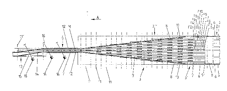
As a further exemplary embodiment, Fig. 3
illustrates a conveying zone that is designated by
the reference numeral 20. Via a section 20', this
conveying zone 20 forms an arrangement for
converting a called-for multi-row stream of
containers or bottles into a single-row stream of
2~ 5
bottles that is to be withdrawn. The conveying
zone or line 20, which is illustrated only
partially in Fig. 3, connects various processing
machines, which are also not illustrated, in a
conventional manner, such as bottle cleaning
machines, filling machines (possibly in combination
with capping machines), labeling machines, packing
apparatus, etc.
Where conveying lines 20 are used, the
conveyor belts 7 as well as the corresponding
narrow conveyor belts 21 are used exclusively not
only in the section 20', i.e. the region of the
feed mechanism 2b, the intermediate conveyor
mechanism 3b and the withdrawal mechanism 4b that
form the arrangement for converting the stream of
bottles, but rather the entire conveying line is
also comprised in all of the other regions or
sections 20" and 20"' exclusively of the narrow
conveyor belts 21, the width of which is equal to
the width of the conveyor belts 7 and in a
direction transverse to the conveying direction is
less than the diameter of the base of the smallest
bottles l that are to be processed with the
apparatus (bottles 1 having the smallest base
diameter). All of the transition zones 9b, 10 and
22 between conveyor belts 21 that follow one
- 22 -
2~ 5
anothe.r in the conveying direction A, even beyond
the intermediate conveyor mechanism 3b, are
respectively provided in a comb-like offset manner,
as was previously described in conjunction with the
transition means or zones 10 in Figs. 1 and 2.
In the embodiment illustrated in Fig. 3, the
withdrawal mechanism ~ comprises three conveyor
belts 7 that are disposed next to one another when
viewed perpendicular to the conveying direction A.
When viewed in the conveying direction A, the
upstream ends of the two outer conveyor belts 7
extend into the intermediate conveyor mechanism 3b,
while the upstream end of the central conveyor belt
7 starts approximately at the transition between
the intermediate conveyor mechanism 3b and the
withdrawal mechanism 4b.
One advantage, among others, of the conveying
line illustrated in Fig. 3 is that along the entire
conveying line each bottle 1 always rests upon at
least two conveyGr belts 7 or 21, and at each
transition zone 9b, 10 and 22 rests upon at least
one conveyor belt 7 or 21, so that to the greatest
extent possible the bottles 1 move without force or
pressure over the transition means 9b, 10 and 22,
and in particular it is not necessary in order to
pass these transition means 9b, 10 and 22 that the
2~ ~?,`~5
bottles 1 be respectively pushed ahead by following
bottles. In this way, it is possible with the
conveying line to also reliably and safely convey
bottles 1 that are unstable with respect to being
able to stand up, such as is the case with plastic
or PET ~polyethylene terephthalate) bottles.
A further advantage is that no bottles stop at
the transition zones 9b, 10 or 22 if there are no
successive bottles 1 as viewed in the conveying
direction. Thus, the conveying line of Fig. 3 can
be operated empty without manual intervention.
A further advantage, among others, is that the
section 20" of the conveying line 20 that follows
the withdrawal mechanism 4b can adjoin the latter
in such a way that the track or direction of the
two correspond with one another, so that the
bottles 1 can pass from the withdrawal mechanism 4b
to the section 20" without the need for parallel
transitions or a change in direction.
The conveyor belts 7 and 21 have, for example,
a width of about 32 mm, so that with the
aforementioned advantages, bottles 1 can be used
that have a base diameter of more than 40 mm, and
preferably greater than 45 mm.
The present invention has been described with
the aid of specific embodiments. However, it is to
- 24 -
Z~3~S
be understood that changes and modifications are
possible without thereby deviating from the basic
concept of the invention. Thus, it is clear that
the use of the arrangement is not limited to the
conversion of a multi-row stream of bottles into a
single-row stream of bottles; rather, the inventive
arrangement can be used for any multi-row stream of
containers, which can be formed from bottles, cans,
or other containers, which is then converted into a
single-row stream of containers.
The present invention is, of course, in no way
restricted to the specific disclosure of the
speciication and drawings, but also encompasses
any modifications within the ~cope of the appended
claims.
- 25 -