Language selection

Search

Patent 2080303 Summary

Third-party information liability

Some of the information on this Web page has been provided by external sources. The Government of Canada is not responsible for the accuracy, reliability or currency of the information supplied by external sources. Users wishing to rely upon this information should consult directly with the source of the information. Content provided by external sources is not subject to official languages, privacy and accessibility requirements.

Claims and Abstract availability

Any discrepancies in the text and image of the Claims and Abstract are due to differing posting times. Text of the Claims and Abstract are posted:

  • At the time the application is open to public inspection;
  • At the time of issue of the patent (grant).
(12) Patent Application: (11) CA 2080303
(54) English Title: DRIVE FOR AUTOMATIC LANCE CHANGE DEVICES
(54) French Title: ENTRAINEMENT POUR MECANISME DE REMPLACEMENT AUTOMATIQUE DE LANCE
Status: Deemed Abandoned and Beyond the Period of Reinstatement - Pending Response to Notice of Disregarded Communication
Bibliographic Data
(51) International Patent Classification (IPC):
  • F27D 3/16 (2006.01)
  • C21C 5/46 (2006.01)
(72) Inventors :
  • STOMP, HUBERT (Luxembourg)
  • DEVILLET, SERGE (Luxembourg)
  • FRIES, DANIEL (Luxembourg)
(73) Owners :
  • PAUL WURTH S.A.
(71) Applicants :
(74) Agent: GOWLING WLG (CANADA) LLP
(74) Associate agent:
(45) Issued:
(22) Filed Date: 1992-10-09
(41) Open to Public Inspection: 1993-04-15
Examination requested: 1999-07-14
Availability of licence: N/A
Dedicated to the Public: N/A
(25) Language of filing: English

Patent Cooperation Treaty (PCT): No

(30) Application Priority Data:
Application No. Country/Territory Date
LU 88 017 (Luxembourg) 1991-10-14

Abstracts

English Abstract


DRIVE FOR AUTOMATIC LANCE CHANGE DEVICES
ABSTRACT
The coupling of lances used for supplying media
by pressing them against a coupling head is effected by
means of draw rods which are operated with the aid of
lifting spindle movement transmitting screw thread
systems. Each draw rod (16, 16') has associated with it
its own reduction gear unit (42, 42') which has an
integrated lifting spindle system and on which a load
cell (34, 34') is mounted. The primary shafts, in
alignment with one another, of the two gear units (42,
42') are connected together by means of a coupling (56)
compensating for axial, radial and angular displacements.


Claims

Note: Claims are shown in the official language in which they were submitted.

- 6 -
PATENT CLAIMS
1. Drive for automatic lance change devices,
particularly for lances which in the production of steel
by a top blowing process have to be coupled and fastened
to a vertically movable lance carriage, in which devices
the lances are pressed against a coupling head, in order
to couple them thereto, by a drive motor with the aid of
two draw rods operated by means of lifting spindle
movement transmitting screw thread systems, each of said
movement transmitting screw thread systems being formed
between the top end of said draw rods and a respective
gear wheel of a reduction gear system for the draw rod
drive, while a load cell is associated with each lifting
spindle system for the purpose of switching off the drive
motor when a determined contact pressure value between
lance and coupling head is reached, characterised in that
each of the two draw rods (16, 16') has associated with
it an individual reduction gear unit (42, 42') housed in
its own casing and having an integrated lifting spindle
system, in that each of said gear units (42, 42') is
mounted on its own load cell (34, 34'), and in that the
primary shafts of the two gear units (42,42'), which
shafts are in principle horizontally in alignment with
one another, are connected together by means of a
coupling (56) compensating for axial, radial and angular
displacements such as can occur between the two gear
units (42, 42') in practical operation.
2. Drive according to Claim 1, characterised in that
the two reduction gear units (42, 42') are supported via
torque struts (44, 44') of the carriage (46) of the lance
change device.
3. Drive according to Claim 1, characterised in that
an angular prereduction gear unit (30) is connected to
the output of the drive motor (28).
4. Drive according to Claim 3, characterised in that
the gear unit (30) is a push-on gear unit having a torque
strut (50) and whose hollow output shaft is pushed over
the input side of the primary shaft of one of the

- 7 -
reduction gear units (42', 42).
5. Drive according to Claim 4, characterised in that
the torque strut (50) is supported on a load cell system
(54) for switching off the drive motor (28) when
impermissibly high forces occur in the drive chain of the
device.
6. Drive according to Claim 5, characterised in that
elastic buffering (52) is provided between the torque
strut (50) and the load cell system (54) in order to
prevent undesirable spontaneous switching-off of the
drive motor (28).
7. Drive according to Claim 4, characterised in that
the torque strut (50) is supported via electric buffering
(52) on the carriage (46) of the lance change device and
a limit switch is provided which is operated by the strut
(50) when a predetermined torque value is reached.

Description

Note: Descriptions are shown in the official language in which they were submitted.


2~3~3
D~IVE_FOR AU~OMA?IC LANC~ C~ANG~ D~VIC~S
The invention relates to a drive for automatic
lance change device~, particularly ~or lances which in
the production of steel by a top blowing process have to
S be coupled and ~astened to a v0rtically movable lanca
carriage, in which device~ the lance3 ar~ p~ ed against
a coupling h~ad, in order to couple them th~reto, by a
drive motor with the aid of. two draw rod~ oporated by
m~an~ of lifting spindle movem~nt transmLtting ~crew
thread ~y~tems, each oE said movement transmitting ~crew
: thread sy~tem~ being f ormed ~etwe~n the top e~d of said
draw rod~ and a r~sp~ctive gear wheel o~ a reduction gear
~y~tem for the draw rod drive, while a load cell i~
associated with each liting spindle 3ystem for the
purpose of ~witching of~ the driYe motor when
determlned contact pressura value between lance and
coupling head i~ reached.
A recent prior art for automatic lance cha~ge
devices of the abovementioned kind is deaGri~ed in the
doc~ment LU-87897, and the presant application i~ to be
regarded as an appli~ation for a pate~t of addition to
this document, so that the latter ia u~ed hereinbelow a~
a reference.
In th~ device according to the document mentioned
the coupling to the aboveme~tioned lance carriage i3
effected with the aid of two lifting spindle ~y~tem~, a~
- external ~crew thread of a draw rod cooperatlng in each
ca~ with an internal scr~w thread in the bore of a gear
wheel.
These gear wheelq may be horizontally di3po~ed
wheel~ in the form of worm whe~ chain wheels, bevel
gears, spiral-toothed gears or cogged-belt geara a~d 80
on, whi~h are mounted axially/radially by their hubs in
a g~ar ~a~ing.
3S In the document mentio~ed worm wheels were 3how~
by way o~ illustration in the appertaining figure~ and
worm8 di~po~ed on a ~ommon ~haft were associated with
~hem. ln t:his connection the re~ark was added that these

2Q~0~03
worm8 may however al~o be mounted on individual ~haft~
which are connected together by meanR of a coupling ~or
~ynchronou~ driving.
: Although the overall concept of the devic~
described in the document mentioned constituted a
sub~tantial advance in relation to the prior art at the
timet practical experience and further reflection have
neverthele~s ~hown that in re~p~ct o~ det~ils
con~iderable LmproVements ar.e 3till po~siblo.
~ first di~advantage o~ th~ device mentioned
con~i~t~ in that the two wo~/wo~m wheel pair~ (or pair~
o~ any other gear wh~el3, ~e~ above) are housed in a
co~mon ca~ing, o that a gear unit o~ this type must
obviously be ~pecially produced. Thi~ common casing also
entail~ the risk that di~placements, which in practical
operation are entirely po si~le, will result in the
tilting of the two lifting spindle sy~tem~, with their
po~sible destruckiorl- Even the optional proviaion o~ a
coupling, which is also mentioned, changes nothing in
thi~ re~pect as long a9 the ~wo worm and worm wheel pairs
are mounted and hou3ed in a rigid common casing. An
Lmportant rea~on for khe provision of a cvupling,
however, consist in that a coupling enable~ the angle of
rotation of the two worm shafts to be mutually adju~tet
on a~3emb1y, in order to ensure that the two lifting
spindle ~ystem~ will work with optimum ~ynchronism, ~o
that when the drive motor iq automatically awitched o~
thes~ ~ystems will press the lance against the coupling
head with a~ preci~ely equal a for~e as po~aible on both
~ide~.
In order to avoid the abo~em~ntioned
disad~antages of the prior art, it i5 there~ore an object
of the invention to provide a drive of the type mentioned
in the preamble, which no longer contain~ spe~ial gear
units and in which ~utual diaplaceme~ts of the two gear
wheel pairs no longer entail any Lmpairment of op~rati~g
reliabili.ty~

3 ~ ~
~ hi~ problem i3 ~olved by a drive of the type
mentioned in the pr~amble which has the featura3
indicated in the characterising part o~ the main claim.
One exemplary em~odLment of the invention i~
illu~trated in the drawing~, in which like part3 are
given the ~ame reference numerals, and is described more
fully below. In the drawing~3:
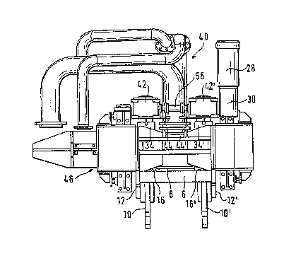
- Figure 1 i a ~ront vi~w of the trive accordi~g
to the i~vention (for th~ ~ake o~ sLmplicity without the
lance sl1spended in po~ition);
- Figure 2 is a plan ~iew of the e~ential part~
of the object shown in Figure 1;
Figure 3 i~ a view in per pective o~ the
e~sential parts o~ the object shown in Figure 1.
- Figure 1 ~hows the essential parts of the driv~
o~ the invention ~or autom2tic lance change devices, and
in it, to ~Lmplify cros~-reference, parts taken over ~rom
- the prior art (Figure l of the reference document) have
bee~ given the same referenc~ numerals as in the latt~r
(3ee in particular parks 6.. .40 in the accompanying
Figure 1).
In this connection it i~ relevant that each draw
ro~ 16, 16' has a~ociated with it an individual
reduction g~ar unit 42 and 42' resp~ctiv~ly, that i~ to
~ay a reductio~ gear u~it hou~ed in its own casing, each
gear unit boing mounted on a load ~ell 34 and 34'
r~sp~ctively. Tho gear unit~ 42, 42' are s2cured again~t
rotation by torque strut~ 44 and 44' respectively, which
ar~ support~d on the carriage 46 of the lance change
devi~e (see al80 Figure~ 2 and 3).
In the ~xemplary em~odLm~nt illu~trated the two
gear units 42' and 42 ar~ drivsn by an electriG motor 28
through a pu~h-on angular reduction gear unit 30 ~hich i~
connected to the output o~ ~aid ~otor and whose output
~haft (not explicitly illu~trated) i~ pu3hed on~o th0
prima~y ~haft of the worm ~ear u~it 42'.
The torque support needed in an arrangement of
thi~ ktnd i9 illu~trated in its co~iguration 48

3 ~1 3
-- 4 --
according to the invention in Figur~ 3. The u~ual torque
~trut 50 on a push-on gear unit 30 o~ this kind i~ here
supported via an ela~tic bu~fer member 52 on a load cell
sy~tem 54 (or th~ like, ~uch as for example a torque
S mea~uring hub) - not explic:itly illu3trated.
The load cell ~y~ta~l54 i~ used to switch o~ the
drive motor 28, independent:Ly of signal~ ~uppli~d by the
load cell~ 34, 34', when determined cri~ical torque
value~ are reached in the Idrive chain, although ba~ore
the load cell ~y9tem 54 i8 loaded the~e value~ are
ela~tically damped ~y the ~uffer member 52 in order to
a~oid exces~ively spontaneous re~pon~e of this sy3tem 54.
The two primary shafts of the two identical gear
units ~2' and 42, which are o~ khe u~ual commercially
1~ availahle type, are connected together via a eoupling 5
such that the pr~mary shaft input ~ide of the gear unit
42 is driven by the prima~y shaft output sids of the gear
unit 42'.
In accordance with the invention the coupling 56
permit~ mutual displacements, which during a sem~ly and
in practical operatio~ are always pos~i~le, between the
two gear unit~ 42 a~d 42', 80 that such di~placement3 can
no longer cause ~eriou~ damage in the drive ~y~tem.
The invention there~ore provide~ a coupling 56
which permlt~ axial, radial a~d angular di~placements
between the gear unit~ 42 and 42~ or their ~aid primary
- ~haft~.
A~ong the n~merou~ couplings available on the
mar~et for such requir~ment~, the ao;called curved tooth
couplings are 3uit~ble ~o~ example.
A coupling o~ the type mentioned permit~ cardanic
displac~ment~ of the two ahafts coupled to~ether and in
addition makes it po~sible during assembly to make a
det~rmined adju~tment of th~ angle of rotation of the two
coup~ ed sh~ft~, ~o that it can be en~ured that the two
hooks 10, 10' will be rai~ed 3ub~tantially ~ynchronously
and the lance (not ~hown) will be preq3ed uniformly on
both ~icles again~t the coupling head 8, which in the

2 ~
-- 5 --
ideal ca:3e would b6~ equivalerlt to a ~multan~aus ~top
command from the two load cell~ 34, 34 ~ to the drive
motor 2 8 .

Representative Drawing
A single figure which represents the drawing illustrating the invention.
Administrative Status

2024-08-01:As part of the Next Generation Patents (NGP) transition, the Canadian Patents Database (CPD) now contains a more detailed Event History, which replicates the Event Log of our new back-office solution.

Please note that "Inactive:" events refers to events no longer in use in our new back-office solution.

For a clearer understanding of the status of the application/patent presented on this page, the site Disclaimer , as well as the definitions for Patent , Event History , Maintenance Fee  and Payment History  should be consulted.

Event History

Description Date
Inactive: IPC from MCD 2006-03-11
Application Not Reinstated by Deadline 2001-10-09
Time Limit for Reversal Expired 2001-10-09
Deemed Abandoned - Failure to Respond to Maintenance Fee Notice 2000-10-10
Amendment Received - Voluntary Amendment 2000-02-22
Letter Sent 1999-07-29
Inactive: Application prosecuted on TS as of Log entry date 1999-07-29
Inactive: Status info is complete as of Log entry date 1999-07-29
Request for Examination Requirements Determined Compliant 1999-07-14
All Requirements for Examination Determined Compliant 1999-07-14
Inactive: Office letter 1997-10-10
Application Published (Open to Public Inspection) 1993-04-15

Abandonment History

Abandonment Date Reason Reinstatement Date
2000-10-10

Maintenance Fee

The last payment was received on 

Note : If the full payment has not been received on or before the date indicated, a further fee may be required which may be one of the following

  • the reinstatement fee;
  • the late payment fee; or
  • additional fee to reverse deemed expiry.

Please refer to the CIPO Patent Fees web page to see all current fee amounts.

Fee History

Fee Type Anniversary Year Due Date Paid Date
MF (application, 5th anniv.) - standard 05 1997-10-09 1997-10-02
MF (application, 6th anniv.) - standard 06 1998-10-09 1998-09-23
Request for examination - standard 1999-07-14
MF (application, 7th anniv.) - standard 07 1999-10-12 1999-10-08
MF (application, 2nd anniv.) - standard 02 1994-10-10
Owners on Record

Note: Records showing the ownership history in alphabetical order.

Current Owners on Record
PAUL WURTH S.A.
Past Owners on Record
DANIEL FRIES
HUBERT STOMP
SERGE DEVILLET
Past Owners that do not appear in the "Owners on Record" listing will appear in other documentation within the application.
Documents

To view selected files, please enter reCAPTCHA code :


To view images, click a link in the Document Description column. To download the documents, select one or more checkboxes in the first column and then click the "Download Selected in PDF format (Zip Archive)" or the "Download Selected as Single PDF" button.

List of published and non-published patent-specific documents on the CPD .

If you have any difficulty accessing content, you can call the Client Service Centre at 1-866-997-1936 or send them an e-mail at CIPO Client Service Centre.


Document
Description 
Date
(yyyy-mm-dd) 
Number of pages   Size of Image (KB) 
Description 1993-11-20 5 206
Claims 1993-11-20 2 75
Drawings 1993-11-20 2 57
Cover Page 1993-11-20 1 16
Abstract 1993-11-20 1 20
Representative drawing 1999-08-26 1 21
Reminder - Request for Examination 1999-06-10 1 118
Acknowledgement of Request for Examination 1999-07-29 1 193
Courtesy - Abandonment Letter (Maintenance Fee) 2000-11-07 1 183
Fees 1998-09-23 1 39
Fees 1997-10-02 2 67
Fees 1997-10-28 2 67
Fees 1999-10-08 1 38
Fees 1996-09-18 1 45
Fees 1995-09-25 1 40
Fees 1994-09-16 1 45