Note: Descriptions are shown in the official language in which they were submitted.
~A
CFO 8781 ~
2 ~
l Magnetic Recording Medium and Method for Examining
Magnetic Recording Medium
BACKGROUND OF THE INVENTION
Field of the Invention
The present invention relates to a magnetic
recording medium, and more particularly to a
ferromagnetic metal thin-film type magnetic recording
medium having properties such as wear resistance, run
stability, durability and environmental resistance
that are required in its practical use. The present
invention also relates to a method for examining the
magnetic recording medium.
lS Related Background Art
In recent years, there are increasing demands
for magnetic recording mediums feasible for high-
density recording as the information capacity has
become greater in the field of information processing
techniques and the quality of pictures or images has
become higher in the field of picture or image
processing techniques. Accordingly, researches and
development for meeting such demands are energetically
made.
In particular, metal thin-film type magnetic
- 2 - 2~810~
1 recording mediums having as a magnetic recording layer
a Co-Ni or Co-Cr ferromagnetic metal thin-film formed
by sputtering or vacuum deposition show great promise
as mediums suited for high-density recording compared
with coated magnetic recording mediums commonly used
at present.
In the metal thin-film type magnetic recording
mediums, differently from coated mediums, the whole
thin-film participates in magnetic recording and
spacing loss can be made very small because of its
high flatness. Utilization of advantages of such
metal thin-film type magnetic recording mediums would
bring about magnetic recording mediums much surpassing
coated magnetic recording mediums in both output and
C/N ratio.
As recording systems, employment of a narrow-
track system and a short wavelength system enables
high-density recording at least several times as
densely as coated magnetic recording mediums.
However, under existing circumstances, various
problems remain in putting the metal thin-film type
magnetic recording mediums into practical use. For
example, in the case of flexible mediums such as video
tapes, video floppy disks, data recording tapes and
floppy disks, the magnetic recording medium runs while
coming into partial contact with a magnetic head to
- 3 - 2~
1 perform recording and reproducing. Accordingly, in
order to achieve the high-density recording, the
probability of contact between the head and the medium
tends to increase since the spacing loss must be made
much smaller. In the case of rigid magnetic recording
mediums comprising a substrate made of glass or non-
magnetic metal, it is common for the medium to be in
contact with the magnetic head when the medium is
standing. In future, the head will be made to run at
a float of about 0.05 um or less to achieve a higher
recording density, probably resulting in an increase
in contact frequency of the recording head with the
medium.
However, the magnetic recording layer formed
of a metal thin film tends to be damaged upon contact
with the magnetic head. When damaged, it may cause a
poor runnability or bring about a lowering of output,
resulting in stop of tape running in an extreme case.
This has been the greatest problem that has hindered
metal thin-film type magnetic recording mediums from
being put into practical use.
Another problem in putting metal thin-film
type magnetic recording mediums into practical use is
that some types of metals used cause corrosion of the
magnetic recording layer formed of a metal thin film
when it is in contact with air over a long period of
- 4 - 2~8~
1 time. For example, a Co-O thin film may be corroded
in a short time in an environment of high temperature
and high humidity or an environment containing salt in
the air.
Coated magnetic recording mediums hitherto
commonly used in video tapes, video floppy disks, data
recording floppy disks and so forth are comprised of a
base film coated with a mixture of a magnetic powder
with a binder, and originally have a finely roughed
surface. Hence, they have a small frictional
resistance. The problem concerning the sliding on the
magnetic head has been solved by adding to the binder
a material having an excellent wear resistance or
lubricity. Thus, their overall reliability has been
improved.
On the other hand, in the metal thin-film type
magnetic recording mediums, it has been attempted to
form a protective layer on the surface of a metal
magnetic layer by the following methods so that the
protective layer imparts to the magnetic recording
medium (1) wear resistance, (2) lubricity and (3)
environmental resistance.
(1) Imparting wear resistance:
An inorganic protective layer comprised of a
hard material is formed on a metal thin-film magnetic
recording layer. For example, a thin film of SiO,
- 5 - 2~ 9~
1 SiO2, SiN, A1203, TiO2 or diamondlike carbon is formed
by vacuum deposition, sputtering or plasma CVD.
(2) Imparting lubricity:
i) A protective layer comprised of a lubricating
material is formed on a metal thin-film magnetic
recording layer or on the aforesaid inorganic
protective layer. For example, a thin film of an
inorganic material such as MoS2, WS2, diamondlike
carbon or amorphous carbon is formed by vacuum
deposition, sputtering or plasma CVD. Alternatively,
a layer of an organic material such as a fluorine
resin, a silicone oil, a surface active agent, a
saturated fatty acid or an ester type oligomer is
formed by solution coating such as spin coating or
dipping, vacuum deposition, or sputtering.
ii) Fine irregularities are formed on the surface
of a magnetic recording medium to decrease true
contact points to lower coefficient of friction.
(3) Imparting environmental resistance:
i) A corrosion-resistant protective layer is
formed. For example, a layer of elemental single
material such as Al, Cr, Ti, V or Si, a layer of an
oxide, nitride, carbide or boride of such an element,
a composite layer of these layers, or a layer of
polymeric material such as polyethylene, polyimide or
nylon is formed by vacuum deposition, sputtering,
- 6 - 2~
l plasma CVD or solution coating.
ii) A water-repellent lubricating layer is formed.
For example, a silane coupling agent or an oil is
coated by solution coating such as spin coating, bar
coating or dipping.
Now, checking the standards of durability of
floppy disks required to have a high reliability, data-
recording floppy disks are required to have a
continuous run durability of 3,000,000 passes or more
10 at normal temperature and 1,000,000 passes or more at
high temperature (about 50C) and low temperature
(about 10C), and video floppy disks, 48 hours (about
10,000,000 passes) in every environment of normal
temperature, high temperature and humidity (40C,
lS 80%RH) and low temperature (-5C).
However, in general, conventional metal thin-
film type magnetic recording mediums cause scratches
or deposits on the recording medium surface or the
head surface after they are made to run several ten
thousand to several hundred thousand passes at best,
resulting in a great lowering of reproduction output.
Thus they can not be said at all to have reached the
level of practical use. Conventional rigid metal thin-
film type magnetic recording mediums also cause
scratches or deposits (masses of fine powder) on the
recording medium surface or the head surface after CSS
~ 7 ~ 2~
l (contact-start-stop) of several to several thousand
times, resulting in a great lowering of reproduction
output.
This causes a damage of the protective layer
itself as a result of its sliding on the magnetic head
because of an insufficient hardness of the
conventional protective layer, and this damage extends
to the magnetic recording layer, where fine powder
produced here adheres to the magnetic head to cause
the head to clog, resulting in an extreme lowering of
reproduction output. In an extreme case, this may
cause a damage such as scratches on the medium or the
head surface to damage the durability of the medium
and head.
A proposal on a magnetic recording medium
making use of a silicon compound in the protective
layer is made (e.g., Japanese Patent Application Laid-
open No. 61-115229, No. 61-178730 or No. 62-229526),
which, however, is still unsatisfactory.
With regard to the data-recording floppy
disks, an example is seen in which a still durability
of 10,000,000 passes or more has been exhibited when a
Co304 film, also serving as a solid lubricating film,
is used as a protective layer of a Co-Cr magnetic
25 layer (Samoto et al., SHINGAKU GIH0 87-15, 1987).
According to an experiment made by the present
- 8 - 2~
1 inventors, however, a thin-film layer comprised of
Co3O4 can give no satisfactory long-term storage
durability and environmental resistance. Under
existing circumstances, the conventional metal thin-
film type magnetic recording mediums, which causecorrosion in the metal thin-film magnetic recording
layer in about O.1 to 10 hours at best ir. an
environmental test (conditions; 85C, 85%RH; target
spec.: 500 hours or more.), have not reached the level
Of practical use.
SUMMARY OF THE INVENTIO_
The present invention solves the problems
discussed above, and provides a magnetic recording
medium excellent in overall reliability such as wear
resistance, environmental resistance and long-term
storage durability.
The magnetic recording medium of the present
invention comprises: a substrate; and a magnetic
recording layer and a protective layer containing
silicon oxide as the main component, which are formed
on at least one surface of the substrate in the order
as mentioned, a sheet resistivity of the protective
layer being 1 x 10¹³ Q/Sq (or Q/~) or more.
The present invention also provides a method
for examining a magnetic recording medium comprising a
- 9 - 2~ 5
1 substrate and a magnetic recording layer and a
protective layer containing a silicon oxide as the
main component, which are formed on at least one
surface of the substrate in the order as mentioned,
the method comprising the steps of;
forming a thin film containing silicon oxide
as the main component, on a silicon wafer under the
same conditions as the conditions for forming the
protective layer; and
examining whether or not the thin film has a
sheet resistivity of 1 x 10¹³ Q/Sq or more.
BRIEF DESCRIPTION OF THE DRAWINGS
Fig. 1 is a partial view to illustrate an
example of the magnetic recording medium of the
present invention.
Fig. 2 is a partial illustration of another
example of the magnetic recording medium of the
present invention.
Fig. 3 is a partial illustration of still
another example of the magnetic recording medium of
the present invention.
Fig. 4 is a partial illustration of a further
example of the magnetic recording medium of the
present invention.
Fig. 5 is a partial illustrat.ion of a still
- 2~
l further example of the magnetic recording medium of
the present invention.
Fig. 6 is a partial illustration of a still
further example of the magnetic recording medium of
the present invention.
Fig. 7 is a partial illustration of a still
further example of the magnetic recording medium of
the present invention.
Fig. 8 is a schematic illustration of an RF
magnetron sputtering apparatus.
Fig. 9 is a plan view of the shape of Al
electrodes used in measurement of sheet resistivity of
the protective layer.
Fig. lO a schematic illustration of an EB
vapor deposition apparatus.
Fig. 11 is a graph to show the relationship
between the sheet resistivity of silicon oxide
protective layers and the frequency of CSS until
scratches appear on magnetic recording mediums.
Fig. 12 shows an example of data of i-V
characteristics of a silicon oxide thin film.
DESCRIPTION OF THE PREFERRED EMBODIMENTS
. _
The magnetic recording medium of the present
invention has a magnetic recording layer comprised of
a ferromagnetic me-tal thin film and a silicon oxide
1 protective layer provided thereon.
Film properties of protective layers are
commonly known to greatly depend on film formation
conditions therefor and vary according to layer
thickness.
The present inventors made extensive studies
on film properties of thin (a few hundred A) films
formed of silicon oxide fundamentally having long-term
storage durability and environmental resistance and on
durability of recording mediums. As a result, they
found that it is very important for the silicon oxide
thin film to be made into a dense film.
They have prepared a medium having a
protective layer formed of a thin film containing
silicon oxide as the main component and having a sheet
resistivity of 1 x 10¹³ Q/Sq (ohm per square) or more,
and have newly discovered that such a medium can
achieve a run durability (pass durability) of
10,000,000 passes or more and a CSS test of 20,000
times or more and can have superior long-term storage
durability and environmental resistance. They have
thus accomplished the present invention.
The present inventors have proposed a magnetic
recording medium having a silicon oxide protective
layer with a specific resistivity of 3.3 x 10¹³ to 5.0
x 1015 Q cm (U.S. Patent Application Serial No.
- 12 - 20~
l 478,837). This magnetic recording medium has an
excellent durability in an environment around normal
temperature. The magnetic recording medium of the
present invention has a more improved durability at
normal temperature and also a superior durability in
an environment of high temperature and humidity and an
environment of low temperature.
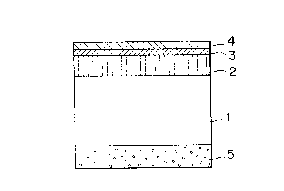
Fig. 1 illustrates a basic structure of the
magnetic recording medium according to the present
invention. On at least one surface of a substrate 1,
a ferromagnetic metal thin film 2 is formed as a
magnetic recording layer, and a thin film 3 containing
silicon oxide as main component is formed thereon as a
protective layer.
The substrate 1 may be made of any materials
hitherto commonly used, such as a non-magnetic metal
such as an aluminum alloy, or glass, and a polymeric
film formed of PET, polyimide, polysulfone,
polyamidoimide, polyether ether ketone or aramid.
On the surfaces of the substrate 1, surface
treatment layers 22 and 22' may be optionally formed
as shown in E'ig. 7. For example, as surface treatment
layers on an aluminum alloy substrate, Ni-P alloy or
anodized aluminum (Alumite) layers may be formed, or
the surfaces of a PET or polyimide film may be coated
with a resin containing a filler.
- 13 - 2~ 3
1 For the purpose of improving lubricity or run
stability, the top surface or back surface of the
substrate may optionally be provided with a number of
fine protuberances (surface irregularities).
In the case when the magnetic layer and
protective layer are formed by thin-film deposition on
the substrate 1 having such surface irregularities,
irregularities substantially corresponding to the fine
irregularities on the surface of the substrate 1 are
formed on the outermost surface. In other words, the
surface roughness of the substrate 1 substantially
coincide with the surface roughness of the magnetic
recording medium formed.
Taking account of spacing loss or dropouts,
the surface roughness of the magnetic recording medium
within the region in which recording and reproducing
is performed may preferably be not higher than 600 A,
and more preferably not higher than 300 A, as a height
of protuberances in the ranking corresponding to the
number at 0.01% of the total number of protuberances
when a statistic distribution of the height of
protuberances is taken up within the region of 10,000
~m and the height of the protuberances in this
statistic distribution is examined in order of height,
and be in a protuberance density ranging from 1 X 10⁴
to 1 x 10¹² protuberances/mm2, more preferably from 1
2 ~
l x 105 to 1 x 10l protuberances/mm2, and still more
preferably from 1 x 10 to 1 x 10 protuberances/mm .
In principle, the higher the protuberance density is,
the more the durability increases. It, however, is
limited on account of the production of base films.
Here, the surface roughness and protuberance
density of the substrate or magnetic recording medium
are measured by the shadowing method, which is a non-
contact measuring method, as disclosed in Japanese
lO Patent Application Laid-open No. 63-188818.
In the case of the rigid substrate, the
surface irregularities can be formed by a method in
which the substrate 1 is polished with a texture tape,
a method in which the substrate 1 is chemically
etched, or a method in which the substrate 1 is coated
with a resin containing a filler that can form surface
irregularities upon drying. In the case of the
flexible substrate, they can be formed by a method in
which a filler is internally added to the substrate 1,
a method in which a resin containing a filler is
coated, or a method in which a resin that can form
surface irregularities upon stretching and drying is
coated.
As the magnetic recording layer 2, it is
possible to use, for example, a ferromagnetic alloy
film mainly composed of Fe, Co and Ni, a ferromagnetic
- 15 - 2 a~
l oxide film or a ferromagnetic nitride film. These
magnetic recording layers can be formed by physical
vapor deposition such as vacuum deposition, ion
plating or sputtering, or plating. Among ~hese, it is
particularly effective for the present invention when
the magnetic recording layer is formed by vacuum
deposition or sputtering and is comprised of a
perpendicularly magnetized film mainly composed of Co.
Fo example, a Co-Cr perpendicularly magnetized film
lO containing 15 to 23% by weight of Cr and 85 to 77% by
weight of Co is effective.
The magnetic recording layer 2 may be either
in a single layer or multi-layers. As shown in Fig.
4, 5 or 6, beneath the magnetic recording layer 2, a
thin film of Al, Ge, Cr, Ti or SiO2 may be provided
for the purpose of improving adhesion to the substrate
1 ~nd improving crystal orientation and magnetic
properties; a high-permeability layer such as an Fe-Ni
layer or a Co-Zr layer, as a backing layer of the
perpendicularly magnetized film; or a Co type semi-
hard magnetic films as an intermediate layer 6 or 6'
for the purpose of securing low-region signals of the
medium.
~he protective layer 3 is comprised of a thin
film mainly composed of silicon oxide, and has a sheet
resistivity of 1 x 10¹³ Q/Sq or more, preferably 1 x
- 16 ~
l 10 Q/Sq or more, and more preferably from 1 x 10
to 1 x 10¹⁷ Q/Sq. A protective layer with a sheet
resistivity less than 1 x 10¹³ Q/Sq may result in a
coarse film and an insufficient hardness and hence may
have a poor wear resistance. A magnetic recording
layer with a sheet resistivity more than 1 X 10¹⁷ Q/Sq
may result in an increase in internal stress of the
film to cause fine cracks in the film, cause
separation of the film from its base or, in the case
of flexible mediums, cause curling.
The silicon oxide contained in the protective
layer 3 as a main component may preferably be in an
amount of 80% by weight or more, and more preferably
85% by weight or more.
The protective layer 3 can be formed by
physical vapor deposition such as vacuum deposition,
ion plating or sputtering, or by solution coating.
When it is formed by physical vapor deposition, it is
preferable to use Si, SiO or SiO2 as a vapor
deposition source, and a feed gas of 30% or less based
on the total pressure (Ar + feed gas).
In the case when the protective layer is
formed by physical vapor deposition, the sheet
resistivity of the protective layer can be controlled~
by regulating degree of ultimate vacuum, pressure of
sputtering gas (mainly argon), partial pressure of
~ 17 - 2 a ~
l feed gas, substrate temperature, power to be applied
(power density of a target), and layer thickness. In
particular, it greatly depends on the sputtering gas
pressure. When, for example, the protective layer 3
is formed using an RF magnetron sputtering apparatus,
the protective layer according to the present
invention can be formed using an SiO2 target under
conditions of an argon gas pressure, i.e., a
sputtering gas pressure, of 0.3 Pa or less (no feed
gas), an applied power of 1 kW or more (when a target
of 6 inches in diameter is used) and a film formation
rate of ~00 A/min or more. When the feed gas is used,
oxygen or hydrogen is suitable. The sheet resistivity
tends to become higher as the sputtering gas pressure
is smaller and the power density is higher.
As for the case in which the protective layer
3 is formed by solution coating, the sheet resistivity
of the protective layer 3 can be controlled by
regulating concentration, curing temperature, curing
time, use or non-use of a heat treatment and its
temperature, and layer thickness.
In the present invention, the sheet
resistivity of the protective layer 3 refers to a
value measured by the following method.
Under the same conditions for the formation of
the silicon oxide film protective layer 3 on the
2a~l~9~
- 18 -
l magnetic recording layer, a silicon oxide film with a
thickness of 1 ~m is formed on a silicon wafer, and
comblike A1 electrodes 16 and 17 as shown in Fig. 9
are formed by vapor deposition on this silicon oxide
film.
The silicon wafer used is available from Japan
Silicon Co., Ltd. under a trade name of SILICON
WAFERS. On the surface of this silicon wafer, a
thermal oxide film is formed in a thickness of about
0.2 ,um by heating. This silicon wafer has the
following specifications:
Crustal: c~
Type: N
Thickness: 510-540 ~m
Diameter: 99.5-100.5 mm
The electrodes 16 and 17 are 0.2 ~m each in
thickness, 0.25 mm in distance W between electrodes,
and 50 mm in length Q at the curve along which both
the electrodes are opposing (in Fig. 9, the length of
the curve from point-A to point-B of the electrode
17).
A DC voltage V1 (10 V at maximum) is applied
between the electrodes 16 and 17. From a value of
leak current i1 on that occasion, sheet resistivity r
is calculated with equation (A):
1 1/ 1 x 50/0.25 (A)
- 19 - 2~8~
l In the above equation (A), 0.25 is the
distance W of the electrodes, and 50 is the length Q
at the curve along which both the electrodes are
Opposing.
Measurement is made using, for example, a
picoammeter (manufactured by YHP Co.; 4140B pA
METER/DC VOLTAGE SOURCE). This measuring apparatus is
placed in a shield box and is purged with nitrogen
after a sample has been set in.
The silicon oxide contained in the protective
layer as a main component may preferably be in a
quantity of 80% by weight or more, and more preferably
85% by weight or more, based on the weight of the
protective layer. The film containing silicon oxide
as the main component has a problem that the internal
stress of the film is large and tends to change
depending on environmental conditions, for example, in
an environment of high temperature and high humidity
(for example, 40C, 80%RH) or low temperature (for
example, -5C~. In general, the inner stress changes
from compression stress to tensile stress as
temperature rises. A great change in internal stress
of the film causes a change in flatness of the
magnetic recording medium, causes cracking of the film
or cause film separation.
Curling also tends to occur in the magnetic
- 20 - ~8~
l recording medium formed, when the protective layer has
an extremely smaller coefficient of thermal expansion
than the ferromagnetic metal thin film that
constitutes the magnetic recording layer.
When there is a possibility of occurrence of
the aforesaid two problems, it is preferred that at
least one element selected from the group consisting
of B, C, N, P, S, Al, Ti, V, Cr, Zn, Ge, Zr, Nb, Mo,
Ta, Mg, Hf, Au and Pt or a compound containing at
least one of these elements is incorporated in the
protective layer. Among these, B, Al203, TiO2, B203,
B205 and MgO are particularly preferred. Any of them
may be added to the extent that does not cause any
lowering of the protective function (wear
characteristics), i.e., in an amount of from 10 to 20%
by weight based on the weight of the protective layer
3.
It is preferable for the substrate 1 to have a
thickness ranging from 0.5 to 3 mm in the case of
rigid disks and to be a non-magnetic substrate. In
the case of tapes or floppy disks, it may preferably
be a polymeric film having a thickness ranging from 3
to 75 ~m. In particular, in the case of floppy disks
with a small diameter as exemplified by floppy disks
of 2 inches in diameter, the substrate may preferably
have a thickness of from 7 ~m to 40 ,um, and more
- 21 - 2~ 8
l preferably from 18 ,um to 35 um.
As for the magnetic recording layer 2, it may
well have a layer thickness of from about 0.1 to 10
~m, and there are no particular limitations.
The protective layer 3 should have a layer
thickness of 500 A or less, and preferably 300 a or
less. The lower limit of the thickness of the
protective layer 3 may be in the extent that does not
damage the function of the protective layer 3, and may
10 be, for example, 50 A or more, and preferably 100 A or
more.
Use of the protective layer haviny such a
layer thickness makes it possible to obtain a magnetic
recording medium in which the spacing loss has been
satisfactorily decreased.
An organic lubricating layer 4 may also be
optionally formed on the protective layer 3. This
enables improvement in wear resistance and durability
under severer environmental conditions as an
environment of high temperature and high humidity or
low temperature.
As materials for the organic lubricating layer
4, it is possible to use a fluorine resin, a silicone
oil, a surface active agent, a saturated fatty acid or
an ester type oligomer. This layer can be formed by
solution coating such as dipping or spin coating or
- 22 - 2~ J~
l physical vapor deposition such as vacuum deposition or
sputtering.
For the silicon oxide protective layer of the
present invention, a lubricating layer comprised of a
water-repellent silane coupling agent is particularly
effective because of its excellent adhesion and water-
repellency in an environment of high temperature and
high humidity.
The organic lubricating layer 4 should have a
10 layer thickness of 100 A or less, and preferably 50 A
or less.
The presence of the organic lubricating layer
4 may cause a spacing loss, similar to the protective
layer. However, the layer thickness as described
above can be effective for sufficiently decrease the
spacing loss.
On the back of the polymeric substrate 1, a
back coat layer 5 may be optionally formed by coating
fo the purpose of lubrication.
The back coat layer 5 may be formed of a
composition commonly used which is prepared by
dispersing inorganic fine particles such as carbon
black, graphite or CaCO3 in a binder such as polyester
resin, polyurethane resin or urethane resin and can be
coated to form a coating.
The magnetic recording medium of the present
- 23 - 2~
l invention may comprise, as shown in Fig. 2, the
polymeric film substrate 1 and, formed on both sides
thereof, magnetic recording layers 2, 2', protective
layers 3, 3' and organic lubricating layers 4, 4', or
may comprise, as shown in Fig. 3, a protective layer
3' to the surface of which the back coat layer 5 is
added. In the magnetic recording medium having the
structure as shown in Fig. 2, the magnetic recording
layers on both sides can be used as magnetic recording
layers.
In Fig. 2, the magnetic recording layers 2 and
2' may have the same thickness when simultaneously
formed. When either layer is formed first, the
curling of the medium may not be well corrected if the
layers are formed in the same thickness. This is
considered due to a change in thermal properties of
the substrate film, which is caused when a magnetic
recording layer is formed on one side of the
substrate, and hence gives conditions substantially
different from those in the formation of the first
magnetic recording layer when another magnetic
recording layer is subsequently formed on the other
side of the substrate. Accordingly, when it is
necessary to control the curling, either magnetic
recording layer 2 or 2' may be appropriately thinner.
Similarly, the silicon dioxide thin films 3 and 3' may
- 24 ~ 0
l also have the same thickness, or either one may be
appropriately made thinner.
The present invention will be specifically
described below by giving Examples.
Example 1
The magnetic recording medium of the present
invention, having the structure as shown in Fig 3 was
produced in the following way.
On both sides of a polyimide film substrate 1
(trade name: Upilex S-Type; available from Ube
Industries, Ltd.; coefficient of thermal expansion:
1.2 X 10 5 cm/cm/C; modulus in tension: 1,020 kg/mm ;
surface roughness: 300 ~ as a height of protuberances
corresponding to the number at 0.01% of protuberances
examined in order of height, and 6 x 10⁶
protuberances/mm2 as a protuberance density), Co-Cr
perpendicularly magnetized films 2 and 2r and
subsequently silicon oxide thin films 3 and 3' were
formed using an RF magnetron sputtering apparatus.
Fig. 8 schematically illustrates the RF
magnetron sputtering apparatus used in the present
Example (a modified apparatus of SPF-300L,
manufactured by NEC Anelva Co., incorporated with a
tape transport system). To the continuous-sheet
polyimide film substrate 1 with a thickness of 25 ~m
and a width of 220 mm, heat treatment was applied in
- 25 -
l vacuo before the formation of the magnetic layers.
Stated specifically, the continuous-sheet polyimide
film substrate 1 was delivered in contact with a
rotating drum 11 (diameter: 500 mm) whose temperature
had been raised to 250C in vacuo and the heat
treatment was applied while maintaining an ultimate
pressure of 2 x 10 3 Pa or less. During the
treatment, the polyimide film substrate 1 was under a
tension of 1.2 kg and was delivered at a speed of 6
cm/min.
After the heat treatment, the system was
evacuated until the degree of ultimate vacuum reached
5 x 10 4 Pa or less, and thereafter the Co-Cr
perpendicularly magnetized films were formed. A
target 13 was 6 inches in diameter, and space between
the target 13 and the substrate 1 was 70 mm. The
target 13 was composed of 80% by weight oL Co and 20%
by weight of Cr. The films were formed under
conditions of an argon gas pressure of 0.1 Pa, an
applied power of 500 W, a film-forming rate of 800
A/min, a rotating drum 11 temperature of 100C, a
polyimide film substrate 1 tension of 1.2 kg and a
film transport speed of 6 cm/min. The Co-Cr magnetic
recording layer thus formed was 0.25 ,um in layer
thickness. After the magnetic recording layer 2 was
formed on one side in this way, the Co-Cr magnetic
- 26 - 2~
l recording layer 2' was also formed on the back surface
under the same conditions for film formation. In Fig.
8, a roller 7 is a roller for feeding the substrate 1;
rollers 8 and 10, transporting rollers; and a roller
~, a wind-up roller. Reference numeral 12 denotes a
shield.
On the Co-Cr magnetic recording layers 2 and
2', the silicon oxide thin films 3 and 3' were
continuously formed as protective layers, using the
same RF magnetron sputtering apparatus. The
protective layers 3 and 3' were formed using an SiO2
target 14 of 6 inches in diameter and under conditions
of a degree of ultimate vacuum of 2.0 x 10 5 Pa, a
rotating drum 11 temperature of 100C, an argon gas
pressure of 0.1 Pa, an applied power of 1 kW and a
film formation rate of 400 A/min. The protective
layers thus formed were each 200 A in thickness.
Next, a silicon wafer of 4 inches in diameter
and with a thermal oxide film on its surface
(available from Nippon Silicon Co., Ltd., with details
as previously noted) was set on the surface of the
drum 11 at its part positioned above the SiO2 target
14 of the sputtering apparatus shown in Fig. 8, and a
silicon oxide film was formed in a layer thickness of
1 um under the same conditions as the aforesaid
silicon oxide thin films 3, 3'. Then, another vapor
- 27 - 2
l deposition apparatus was set up and Al electrodes were
formed in a thickness of 0.2 ,um in the form as shown
in Fig. 9.
The i-V characteristics of the present sample,
measured with a picoammeter are shown in Fig. 12.
From this graph, the present sample was confirmed to
have a sheet resistivity of 5.0 X 10 Q/Sq.
Pinhole density of the silicon oxide thin
films 3 and 3' was also measured by the copper
decoration method (which utilizes electrochemical
reaction occurring in an organic solvent, and is
detailed in Shiono and Yashiro, Applied Physics, Vol.
45, No. 10, 1976, p.952, entitled "Evaluation of
Pinholes in SiO2 Thin Films") to reveal that it was
3.1 holes/cm on the average.
Subsequently to the formation of the
protective layers 3 and 3', a solution prepared by
diluting fluorosilane with IPA to a fluorosilane
concentration of 0.1% by weight was coated on the
protective layer 3 by spin coating in a thickness of
20 A .
Next, only on the protective layer 3', a back
coat solution (trade name: TPB-3091 Black; available
from Toyo Ink Mfg. Co., Ltd.) comprising a polyester
type binder incorporated with carbon black and fine
CaC03 particles was coated to form a back coat layer 5
- 28 - 2~ 9~
l in a thickness of 0.5 ~m.
The magnetic recording medium thus produced
was punched into a disk of 45 mm in diameter to give a
video floppy disk.
The video floppy disk obtained was set on a
commercially available video floppy disk drive deck la
modified player of Canon Still Video Player RV301
(trade name, manufactured by Canon Inc.) to measure
C/N (9 MHz) and make an environmental durability test.
In the durability test, only reproducing was
carried out after signals of 9 MHz were recorded, and
the time by which the reproducing output attenuated to
a value of the initial value minus 3 dB was defined as
durability time. The durability was evaluated on the
basis of this durability time.
The durability test of the video floppy disk
was carried out using its 25th track and in an
environment of normal temperature (23C, 60%RH), an
environment of high temperature and high humidity
(40C, 80%RH) and an environment of low temperature
(-5C).
The C/N of the magnetic recording medium of
the present Example was ~8.0 dB, assuming as 0 dB the
C/N level of a commercially available coated medium
(trade name: Canon Video Floppy Disk VF-50;
manufactured by Canon Inc.; hereinafter "MP") (C/N
- 29 - 2~
1 level of MP: hereinafter "MPL").
In the durability test in the normal
temperature environment, the reproduction output
dropped by 0.2 dB with respect to the initial value,
on the lapse of 48 hours (about 10,000,000 passes).
In the durability test in the high temperature
and high humidity environment, the reproduction output
dropped by 1.5 dB with respect to the initial value,
on the lapse of 48 hours.
In the durability test in the low temperature
environment, the reproduction output dropped by 0.8 dB
with respect to the initial value, on the lapse of 48
hours.
From the above results, the video floppy disk
obtained in the present Example was proved to have a
greatly large C/N and also have a reliance durability
at the level of practical use.
The video floppy disk obtained in the present
Example was left to stand in a natural environment for
a year and thereafter the evaluation was made in the
same manner as described above, so that the same
results were obtained. This proves that the magnetic
recording medium of the present invention also has a
superior storage durability.
Example 2
A magnetic recording medium (a video floppy
- 30 - 2Q~9~
l disk) was produced in the same manner as in Example l
except that the protective layers, silicon oxide thin
fi'ms 3 and 3', were formed under film-forming
conditions in which the argon gas pressure was changed
to 0.13 Pa.
The silicon oxide thin films thus formed had a
sheet resistivity of l.0 x lOl4 Q/~q.
The measurement of C/N and the durability test
on the video floppy disk obtained were made in the
same manner as in Example l. Results obtained are
shown in Table 1.
Namely, C/N (9 MHz) was MPL + 7.l dB.
In the still durability test in the normal
temperature environment, the reproduction output
dropped by l.0 dB with respect to the initial value,
on the lapse of 48 hours ~about lO,000,000 passes).
In the durability test in the high temperature
and high humidity environment, the reproduction output
dropped by 2.0 dB with respect to the initial value,
on the lapse of 48 hours.
In the durability test in the low temperature
environment, the reproduction output dropped by l.6 dB
with respect to the initial value, on the lapse of 48
hours.
From the above results, the video floppy disk
obtained in the present Example was proved to have a
2 ~ 3
l greatly large C/N and also have a reliance durability
at the level of practical use.
Example 3
A magnetic recording medium (a video floppy
disk) was produced in the same manner as in Example 1
except that the protective layers, silicon oxide thin
films 3 and 3', were formed under film-forming
conditions in which the argon gas pressure was changed
to 0.16 Pa.
The silicon oxide thin films thus formed had a
sheet resistivity of 6.0 x 10¹³ Q/Sq.
The measurement of C/N and the durability test
on the video floppy disk obtained were made in the
same manner as in Example 1. Results obtained are
shown in Table 1.
C/N was MPL + 5.3 dB.
In the still durability test at normal
temperature, the reproduction output dropped by 1.9 dB
with respect to the initial value, on the lapse of 48
hours (about 10,000,000 passes).
In the durability test in ~he high temperature
and high humidity environment, the durability time was
30 hours (about 6,500,000 passes).
In the durability test in the low temperature
environment, the durability time was 40 hours (about
8,600,000 passes).
- 32 - 2~8~
1 From the above results, the video floppy disk
obtained in the present Example was proved to have a
greatly large C/N and also, although the durability
time did not reach 48 hours in the high temperature
and high humidity environment and the low temperature
environment, well satisfied a target level (1,000,000
passes or more in the high temperature and high
humidity environment and the low temperature
environment) of data recording floppy disks. Namely,
its reliance durability was proved to be at the level
of practical use.
Example 4
A magnetic recording medium (a video floppy
disk) was produced in the same manner as in Example 1
except that the protective layers, silicon oxide thin
films 3 and 3', were formed under film-forming
conditions in which the argon gas pressure was changed
to 0.2 Pa.
The silicon oxide thin films thus formed had a
sheet resistivity of 1.0 x 10¹³ Q/Sq.
The measurement of C/N and the durability test
on the video floppy disk obtained were made in the
same manner as in Example 1. ~esults obtained are
shown in Table 1.
2S C/N was MPL + 3.0 dB.
In the still durability test at normal
- 33 - 2~
l temperature, the reproduction output dropped by 2.5 dB
with respect to the .initial value, on the lapse of 48
hours (about 10,000,000 passes).
In the durability test in the high temperature
and high humidity environment, the durability time was
5 hours (about 1,100,000 passes).
In the durability test in the low temperature
environment, the durability time was 9 hours (about
1,900,000 passes).
10From the above results, the video floppy disk
obtained in the present Example was proved to have a
greatly large C/N and also, although the durability
time did not reach 48 hours in the high temperature
and high humidity environment and the low temperature
15environment, well satisfied a target level (1,000,000
passes or more in the high temperature and high
humidity environment and the low temperature
environment) of data recording floppy disks. Namely,
its reliance durability was proved to be at the level
of practical use.
Comparative Example 1
~ magnetic recording medium (a video floppy
disk) was produced in the same manner as in Example 1
except that the protective layers, silicon oxide thin
films 3 and 3', were formed under film-forming
conditions in which the argon gas pressure was changed
2~
l to 0.3 Pa.
The silicon oxide thin films thus formed had a
sheet resistivity of 5.3 x 10¹² Q/Sq.
The measurement of C/N and the durability test
on the video floppy disk obtained were made in the
same manner as in Example 1. Results obtained are
shown in Table 1.
C/N was MPL + 1.0 dB.
Durability test results were as follows: The
durability time was 13 hours (about 2,800,000 passes)
in the normal temperature environment, 4 hours (about
900,000 passes) in the high temperature and high
humidity environment, and 8 hours (about 1,700,000
passes in the low temperature environment, showing an
extremely poor durability in the high temperature and
high humidity environment.
In the medium after the durability test,
scratches were found to have occurred and powder was
found to have adhered around the scratches. Many
scratches and deposits were also seen on the surface
of the head.
Example 5
A magnetic recording medium (a video floppy
disk) was produced in the same manner as in Example 1
except that no lubricating layer was formed.
The protective layers formed here had a sheet
- 35 -- 2~
l resistivity of 5.0 x 10¹⁴ Q/Sq.
The measurement of C/N and the durability test
on the video floppy disk obtained were made in the
same manner as in Example 1. Results obtained are
shown in Table 1.
C/N was MPL + 8.0 dB. With regard to the
durability, the durability time was 48 hours (about
10,000,000 passes) in the normal temperature
environment, which was substantially the same as in
Example 1 (reproduction output was minus 0.5 dB from
the initial value, on the lapse of 48 hours), but 20
hours (about 4,300,000 passes) in the high temperature
and high humidity environment. In the low temperature
environment, the durability time was 25 hours (about
5,400,000 passes).
From the above results, the video floppy disk
obtained in the present Example was proved to have a
greatly large C/N and also, although the durability
time did not reach 48 hours in the high temperature
and high humidity environment and the low temperature
environment, well satisfied a target level (1,000,000
passes or more in the high temperature and high
humidity environment and the low temperature
environment) of data recording floppy disks. Namely,
its reliance durability was proved to be at the level
of practical use.
- 36 - 2~
l Example 6
A magnetic recording medium (a video floppy
disk) was produced ln the same manner as in Example 1
except that Upilex S-Type (available from Ube
Industries, Ltd.) having a coefficient of thermal
expansion of 1.2 x 10 5 cm/cm/C, a modulus in tension
of 1,050 kg/mm2 and a surface roughness Rmax of 50 A
or less and provided with no fine irregularities on
its surface was used as the polyimide film substrate
10 1.
The protective layers formed here had a sheet
resistivity of 5.0 x 101 Q/Sq.
The measurement of C/N and the durability test
on the video floppy disk obtained were made in the
same manner as in Example 1. Results obtained are
shown in Table 1.
C/N was MPL + lO.0 dB. With regard to the
durability, the durability time was 14 hours (about
3,000,000 passes) in the normal temperature
environment, 5 hours (about 1,100,000 passes) in the
high temperature and high humidity environment, and 8
hours (about 1,700,000 passes) in the low temperature
environment. The medium in which no fine
irregularities were formed on its surface enabled
decrease in spacing loss and improvement in
reproduction output (C/N), but brought about a slight
_ 37 _ 2~ 9
l lowering of durability. ~owever, the durability was
within the range of the level of practical use
required for data recording floppy disks.
Example 7
A magnetic recording medium (a video floppy
disk) was produced in the same manner as in Example 1
except that a TiO2 pellet was welded to an SiO2 target
of 6 inches in diameter so as to give its area ratio
of about 15% and the resulting target was used as the
target used for the formation of the protective
layers.
The Si-Ti-0 thin films thus formed had a sheet
resistivity of 2.8 x 10¹⁴ Q/Sq.
The measurement of C/N and the durability test
on the video floppy disk obtained were made in the
same manner as in Example 1. Results obtained are
shown in Table 1.
C/N was MPL + 6.8 dB. With regard to the
durability, the durability time was 48 hours (about
20 10,000,000 passes) in the normal temperature
environment, about 35 hours (about 7,600,000 passes)
in the high temperature and high humidity environment,
and 48 hours or more in the low temperature
environment. The medium in which the protective layer
containing silicon oxide as the main component was
changed to the layer comprising Si-0 to which Ti was
- 38 - 2
l added as an additive element enabled improvement in
the durability in the high temperature and high
humidity environment and the low temperature
environment.
Example 8
The magnetic recording medium of the present
invention, having the structure as shown in Fig 1 was
produced in the following way.
On the surface of a 7.5 ~m thick polyimide
film substrate 1 (trade name: Upilex Copolymer Type;
available from Ube Industries, Ltd.; coefficient of
thermal expansion: 1.5 X 10 5 cm/cm/C; modulus in
tension: 580 kg/mm2; surface roughness: 320 A as a
height of protuberances corresponding to the number at
0.01% of protuberances examined in order of height,
and 5 X 10⁶ protuberances/mm as a protuberance
density), a Co-Cr perpendicularly magnetized film 2
was formed by electron beam (EB) vapor deposition.
Fig. 10 schematically illustrates an EB
apparatus used in the present Example.
No preheating of the polyimide film substrate
1 was carried out. The temperature of a rotating drum
11 was set to 200UC, and a vapor deposition source 15
comprised of an alloy of 80% by weight of Co and 20%
by weight of Cr was exposed to electron beams to
continuously carry out vapor deposition. The film
- 39 - 2~ 5
l formation was at a rate of 0.5 ~m/min and in a layer
thickness of 0.35 ~m.
Next, on the Co-Cr perpendicularly magnetized
film 2, the silicon oxide thin film 3 was formed by
sputtering as the protective layer. The protective
layer was formed using the same apparatus as used in
Example 1 and using as the target an SiO2 target of 6
inches in diameter, under conditions of a rotating
drum temperature of 200C, an argon gas pressure of
0.1 Pa, an 2 partial pressure of 20%, an applied
power of 1 kW and a film formation rate of 400 A/min.
The film thus formed was in a layer thickness of 100
. The protective layer comprising the silicon oxide
thin film formed here had a sheet resistivity of 2.0 x
1ol5 Q/Sq
Next, on the protective layer 3, a film of FEP
resin (available from Du Pont Co.) was formed in a
thickness of about 20 A as the lubricating layer 4.
On the back of the polyimide film substrate 1,
the back coat layer 5 was formed by coating. Its
material was comprised of a urethane type binder
containing carbon black and fine TiO2 particles (trade
name: TB-5014 Black; available from Toyo Ink Mfg. Co.,
Ltd.), and its layer thickness was 0.5 ,um.
The magnetic recording medium thus produced
was cut in a width of 8 mm to give a magnetic tape.
- 40 2~ 95
l Using the magnetic tape obtained, recording
and reproducing were performed on a commercially
available 8 mm video deck (EV-A80; manufactured by
Sony Corp.) to evaluate RF reproduction output, pass
durability and still durability. Results obtained are
shown in Table 2.
Here, the pass durability test is carried out
by putting the tape to pass run of only reproduction
after RF signals have been recorded. The time by
which the reproduction output attenuates to a value of
the initial value minus 3 dB is defined as pass
durability time to make evaluation. A target
specification of the level of practical use is 200
passes.
The still durability test is carried out by
putting the tape to still run of only reproduction
after RF signals have been recorded. The time by
which the reproduction output attenuates to a value of
the initial value minus 3 dB is defined as still
durability time to make evaluation. A target
specification of the level of practical use is 120
minutes.
In the present Example, the RF reproduction
output was 4.0 dB higher than the RF reproduction
output of a commercially available coated tape (trade
name: Canon 8 mm Video Tape P-6; manufactured by Canon
- 41 - 2~8 ~a9
l Inc.) (hereinafter "MPL"'). Both the pass durability
and the still durability were at the level of
practical use.
Example 9
A magnetic tape was produced in the same
manner as in Example 8 except that the protective
layer, silicon oxide thin film 3, was formed under
film-forming conditions in which the argon gas
pressure was changed to 0.1 Pa and the oxygen partial
pressure to 25%.
The silicon oxide thin film thus formed had a
sheet resistivity of 1.0 x 10¹⁶ Q/Sq.
Evaluation on the magnetic tape obtained was
made in the same manner as in Example 8. Results
obtained are shown in Table 2.
RF reproduction output was MPL' + 3.7 dB.
Both the pass durability and the still durability were
at the level of practical use.
Example 10
A magnetic tape was produced in the same
manner as in Example 8 except that the protective
layer, silicon oxide thin film 3, was formed under
film-forming conditions in which the argon gas
pressure was changed to 0.1 Pa and the oxygen partial
pressure to 30%.
The silicon oxide thin film thus formed had a
- 42 - 2 ~ ~ 0 ~
l sheet resistivity of 1.0 x 10¹⁷ Q/Sq.
Evaluation on the magnetic tape obtained was
made in the same manner as in Example 8. Results
obtained are shown in Table 2.
RF reproduction output was MPL' + 3.3 dB.
Both the pass durability and the still durability were
at the level of practical use.
Example 11
The medium having the structure as shown in
Fig. 7 was produced in the following way.
First, on a 1.27 mm thick aluminum alloy
substrate 1, aluminum anodizing was applied by a known
method to form aluminum oxide surface-treated layers
22 and 22' each in a thickness of about 15 ~m.
Subsequently, their surfaces were mirror-polished and
then thoroughly washed. The substrate thus treated
was set in a sputtering apparatus, and an in-line
system was operated to successively form Mo-Cu-
Permalloy (JIS C-2531; compositional ratio: 78% Ni, 4%
Mo, also containing Cu and Cr, and the balance of Fe)
films 6 and 6' as soft magnetic layers and Co-Cr
perpendicularly magnetized films 2 and 2' as magnetic
recording layers by magnetron sputtering in a
thickness of 0.5 ~m for each. These were formed under
conditions of a substrate temperature of 120C, a
target size of 8 inches (203.2 mm) in diameter, a Co-
- 43 - 2~
1 Cr target composition of 80 % by weight of Co and 20%
by weight of Cr, an argon gas pressure of 0.2 Pa, an
applied power of 1 kW and a film formation rate of 400
A/min .
Next, on the Co-Cr magnetic layers 2 and 2',
silicon oxide thin films 3 and 3' were formed as the
protective layers, using an RF magnetron sputtering
apparatus. This formation was carried out using SiO2
target of 6 inches in diameter under conditions of a
substrate temperature of 120DC, an argon gas pressure
of 0.1 Pa, an applied power of 1 kW and a film
formation rate of 400 A/min. The films formed were
each in a thickness of 270 A.
The sheet resistivity of each silicon oxide
thin film thus formed was measured to reveal that it
was 7.0 x 10¹⁴ Q/Sq.
Next, on the protective layers 3 and 3',
lubricating layers 4 and 4' were formed by spin-
coating an IPA dilute solution of fluorosilane in a
concentration of 0.5% by weight so as to give a dried
coating thickness of 30 A, and further coating thereon
a Freon dilute solution of Krytox (available from Du
Pont Co.) in a concentration of 0.05% by weight so as
to give a dried coating thickness of 30 A.
Electromagnetic conversion characteristics of
the magnetic recording medium thus obtained, having a
2 ~ 9 5
1 diameter of 3.5 inches in diameter, was measured. As
a result, high-density recording of 70 kbpi was
possible.
The magnetic recording medium was also set on
a 3.5 inch hard disk drive SRD2040Z, manufactured by
Sony Corp., and CSS tests were carried out 10 times on
different tracks. Results obtained are shown in Fig.
11. The frequency of CSS until scratches appear on
the medium was 50,000 to 70,000 times. At 20,000
times, a borderline of the level of practical use,
neither changes nor damages were seen at all in the
medium.
The medium was also left to stand in an
environment of high temperature and high humidity
lS (85C, 85%RH) for 500 hours. However, no changes were
seen in the medium.
From the above results, the medium of the
present Example can be said to have a greatly higher
reproduction output than conventional coated magnetic
recording mediums, and also have durability, wear
resistance and environmental resistance all at the
level of practical use.
Example 12
A magnetic recording medium was produced in
the same manner as in Example 11 except that the
protective layers, silicon oxide thin films 3 and 3',
- 45 - 2a8l 095
l were formed under film-forming conditions in which the
argon gas pressure was changed to 0.15 Pa.
The silicon oxide thin films 3 and 3' thus
formed had a sheet resistivity of 1.0 x 10 Q/Sq.
Evaluation on the medium obtained was made in
the same manner as in Example 11. As a result, as
shown in Fig. 11, the frequency of CSS until scratches
appear on the medium was 25,000 to 40,000 times. In
the high temperature and high humidity environment
test as shown in Example 11, no changes were seen on
the present medium for 500 hours or more. The present
medium also showed substantially the same
electromagnetic conversion characteristics as the
medium of Example 11.
Example 13
A magnetic recording medium was produced in
the same manner as in Example 11 except that the
protective layers, silicon oxide thin films 3 and 3',
were formed under film-forming conditions in which the
argon gas pressure was changed to 0.25 Pa.
The silicon oxide thin films 3 and 3' thus
formed had a sheet resistivity of 1.0 X 10¹³ Q/Sq.
Evaluation on the medium obtained was made in
the same manner as in Example 11. ~s a result, as
shown in Fig. 11, the frequency of CSS until scratches
appear on the medium was 21,000 to 30,000 times.
- 46 - ~8
l In the high temperature and high humidity
environment test as shown in Example ll, no changes
were seen on the present recording medium for 500
hours or more. The present medium also showed
substantially the same electromagnetic conversion
characteristics as the medium of Example 11.
Comparative Example 2
A magnetic recording medium was produced in
the same manner as in Example 11 except that the
protective layers, silicon oxide thin films 3 and 3',
were formed under film-forming conditions in which the
argon gas pressure was changed to 0.4 Pa.
The silicon oxide thin films 3 and 3' thus
formed had a sheet resistivity of 3.0 X 10¹² Q/Sq.
Evaluation on the medium obtained was made in
the same manner as in Example 11. As a result, as
shown in Fig. 11, the frequency of CSS until scratches
appear on the medium was 1,000 to 5,000 times. For
the purpose of practical use, mediums had to be
durable to 20,000 time CSS tests, but the medium of
the present Comparative Example did not show the
durability reaching the level of practical use in all
tracks.
The high temperature and high humidity
environment test as shown in Example 11 was also made
on the medium of the present Comparative Example. As
_ 47 _ 2~
l a result, minute corrosions had occurred at two or
three points. The medium of the present Comparative
Example showed substantially the same electromagnetic
conversion characteristics as the medium of Example
11.
From the above results, the medium of the
present Comparative Example was proved to have a
greatly high reproduction output, but have no
durability and wear resistance reaching the level of
practical use. It also had a problem in environmental
resistance.
Example 14
A magnetic recording medium was produced in
the same manner as in Example 11 except that the
protective layers, silicon oxide thin films 3 and 3',
were formed under film-forming conditions in which the
argon gas pressure was changed to 0.1 Pa.
The silicon oxide thin films 3 and 3' thus
formed had a sheet resistivity of 1.0 X 10¹⁷ S2/Sq.
Evaluation on the medium obtained was made in
the same manner as in Example 11. As a result, as
shown in Fig. 11, the frequency of CSS until scratches
appear on the medium was 20,000 to 30,000 times.
In the high temperature and high humidity
environment test as shown in Example 11, little
changes were seen on the present recording medium for
~o~9~
- 48 -
1 500 hours or more, but cracks were partially produced
therein to the extent there was no problem in
practical use. The present medium also showed
substantially the same electromagnetic conversion
characteristics as the medium of Example 11.
- 49 - 2~
l Table 1
Sheet Durability time (hrs)*2
resis- C/N*1 Normal High temp. Low
tivity (9MHz) temp. High humid. temp.
(Q/Sq) (dB) (23C,60%RH) (40C,80%RH) (-5C)
Example:
1 5.0x10¹⁴ +8.0 >48 >48 >48
2 l.OX10l4 +7.1 >48 >48 >48
3 6.0x10¹³ +5.3 >48 30 40
4 l.OX10l3 +3.0 >48 5 9
Comparative Example:
1 5.3X10¹² +1.0 13
5.0x10¹⁴ +8.0 >48 20 25
6 5.0x10¹⁴+10.0 14 5 8
7 2.8x10¹⁴ +6.8 >48 35 >48
Table 2
Sheet *1 Pass *3 Still *3
resistivity RF output durability durability
20(Q/Sq) (dB) (times) (times)
Example:
8 2.0X10l5 +4.0 >200 >120
9 1.0xlo16 +3 7 >200 >120
10 1.0X10¹⁷ ~3 3 >2~0 >120
2 a ~
- 50 -
l *1: The output level of the commercially available
coated magnetic recording medium (MP) is assumed as 0
dB.
*2: The durability time refers to the time by
which the reproducing output has attenuated to a value
of the initial value minus 3 dB. The level of
practical use required for floppy disks is 3,000,000
passes or more (about 13 hours in the case of video
floppy disks) in the normal temperature environment
lO and 1,000,000 passes or more (about 5 hours) in the
high temperature and high humidity environment.
*3: The time by which the reproducing output has
attenuated to a value of the initial value minus 3 dB
is regarded as durability time. The level of
practical use is 200 passes or more in the pass
durability and 120 minutes or more in the still
durability.
As described above, as the protective layer
formed on the magnetic recording layer, the magnetic
recording medium of the present invention has the thin
film containing silicon oxide as the main component,
having a sheet resistivity of 1 x 10¹³ Q/Sq or more,
preferably 1 x 10¹⁴ Q/Sq or more, and more preferably
from 1 x 10¹⁴ to 1 x 10¹⁷ Q/Sq, and hence has superior
wear resistance, environmental durability and long-
term storage durability.