Language selection

Search

Patent 2081253 Summary

Third-party information liability

Some of the information on this Web page has been provided by external sources. The Government of Canada is not responsible for the accuracy, reliability or currency of the information supplied by external sources. Users wishing to rely upon this information should consult directly with the source of the information. Content provided by external sources is not subject to official languages, privacy and accessibility requirements.

Claims and Abstract availability

Any discrepancies in the text and image of the Claims and Abstract are due to differing posting times. Text of the Claims and Abstract are posted:

  • At the time the application is open to public inspection;
  • At the time of issue of the patent (grant).
(12) Patent Application: (11) CA 2081253
(54) English Title: AUTOCLAVE
(54) French Title: AUTOCLAVE
Status: Deemed Abandoned and Beyond the Period of Reinstatement - Pending Response to Notice of Disregarded Communication
Bibliographic Data
(51) International Patent Classification (IPC):
  • B01J 3/04 (2006.01)
  • B01J 3/00 (2006.01)
  • C04B 40/02 (2006.01)
(72) Inventors :
  • WOSNITZA, FRANZ (Germany)
  • BECKMANN, GEORG (Austria)
  • ZIMMERMANN, GEORG (Germany)
  • WOSNITZA, FRANZ (Germany)
  • BECKMANN, GEORG (Austria)
  • ZIMMERMANN, GEORG (Germany)
(73) Owners :
  • HEBEL AKTIENGESELLSCHAFT
  • SICOWA VERFAHRENSTECHNIK FUR BAUSTOFFE GMBH & CO. KG
(71) Applicants :
  • HEBEL AKTIENGESELLSCHAFT (Germany)
  • SICOWA VERFAHRENSTECHNIK FUR BAUSTOFFE GMBH & CO. KG (Germany)
(74) Agent: MARKS & CLERK
(74) Associate agent:
(45) Issued:
(22) Filed Date: 1992-10-23
(41) Open to Public Inspection: 1993-04-25
Availability of licence: N/A
Dedicated to the Public: N/A
(25) Language of filing: English

Patent Cooperation Treaty (PCT): No

(30) Application Priority Data:
Application No. Country/Territory Date
P 41 35 118.5 (Germany) 1991-10-24

Abstracts

English Abstract


ABSTRACT
The invention relates to an autoclave for treating charged materials (6) with vapour
under pressure, with a substantially cylindrical inner chamber (2) surrounded by an
autoclave casing (1) and with a heating device (8) responsive to a heated heat
transfer medium to generate vapour in the inner chamber (2). In order to providethe heating in a way which is favourable structurally and in terms of energy, it is
provided that the heating device (8) is arranged within one of the curved side
regions of the autoclave casing (1), and consists of at least one flue (10) arranged
substantially vertically in the autoclave and a heat exchanger (11) arranged in the
lower inflow region of the flue (10) and through which flows a heat transfer
medium, so that a convection flow results circulating substantially in the
circumferential direction of the casing (1) of the autoclave.


Claims

Note: Claims are shown in the official language in which they were submitted.

THE EMBODIMENTS OF THE INVENTION IN WHICH AN EXCLUSIVE
PROPERTY OR PRIVILEGE IS CLAIMED ARE DEFINED AS FOLLOWS:
1. An autoclave for treating charged materials with vapour under pressure with
a substantially cylindrical inner chamber surrounded by an autoclave casing and
with a heating device responsive to a heated heat transfer medium to generate
vapour in the inner chamber from characterized in that the heating device (8) isarranged within one of the curved side regions of the autoclave casing (1) and
consists of at least one flue (10) arranged substantially vertically in the autoclave
and a heat exchanger (11) arranged in the lower inflow region of the flue (10) and
through which flows a heat transfer medium so that a convection flow-results
circulating substantially in the circumferential direction of the casing (1) of the
autoclave.
2. An autoclave according to claim 1 characterized in that the flue (10) is
roughly matched to the curvature of the casing (1) of the autoclave.
3. An autoclave according to claim 1 or 2 characterized in that the flue (10)
and the heat exchanger (11) are fitted on a bracket (9) attached to the casing (1) of
the autoclave.
4. An autoclave according to any one of claims 1 to 3 characterized in that the
flue (10) is tapered like a nozzle at the outlet end.

Description

Note: Descriptions are shown in the official language in which they were submitted.


~UTOCLAVE ;~ 5~
This invention relates to an autoclave for treating charged materials with
vapour under pressure, with a substantially cylindrical inner chamber surrounded by
an autoclave casing and wi~h a heating device responsive to a heated heat transfer
S medium to generate vapour in the inner chamber.
Such an autoclave is known from EP-B 0133 239, in which the autoclave
casing is made double-walled in order eilher that a heated heat carrying material
such as hot oil can flow through directly or that it can receive heating coils, through
which the heat transfer medium flows. SUCh autoclave heating is costly in terms of
structure and energy, as well as slow.
The object of the invention is to provide an autoclave of the kind initially
recited, whose healing is simplified structurally, which is favourable in terms of
energy and is easy to control.
The object is attained according to the invention in that the heating device is
arranged within one of ~he curved side regions of the autoclave casing, and consists
of at least one flue arranged substantially verticall~ in the autoclave and a heat
exchanger arranged in the lower inflow region of the flue and through which flows
a heat transfer medium, so that a convection flow resulls circulating substantially in
the circumferential direction of the ca.sing of the autoclave.
Further development.s of the invention tvill be found in the ensuing
description and the dependerlt claims.
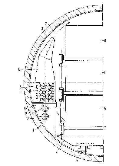
The invenlion will now be e,Yplained in more detail ~vith reference to an
autoclave sho~Yn partially in radial section.
The illustrated autoclave comprises an autoclave casing 1, which encloses a
.substantially cylinclrical inner chamber 2, i~s provided at one end or at both end~s
with a charging opening closed by a co~er and ilas heat insulation 3 outside, inorcler to keep heat losses as small as possible.
In the illu~st,ratecl embodiment of the autoclave, rails 4 are fitted in the
autoclave casing I at the bottom, in order to be able to cl-arge the autoclave with
trolleys 5, which carry charged ma~erials 6, e.g. moulcled bodies of materials ---
containing hardenens to be harclened by vapour, on pallets 7, which are stacked O,
the trolley 5.

-2- z~3 ,r~
In one of the curved regions at the side of the autoclave casing 1, which are
in any event not occupied by the charged materials, there is arranged a heating
device 8, which is mounted on a bracket 9. The heating device 8 consists of at least
one flue 10 arranged substantially vertically and vhich preferably extends over at
5 least half the height of tlle autoclave casing 1 and is roughly matched to thecurvature of the latter, and a heat exchanger 11, which is arranged in the lower,
inflow region of the flue 10 and is connected to a flow line 12 and a return line 13
for heating oil, ~vhich can be heated outside the autoclave by means of a heating oil
heater. ~ccordingly, as a result of the free convection in operation of the heat10 exchanger 11 through the flue 10 lhere is generated a circulating flowin the
circumferential direction of the autoclave casing 1, wherewith the saturated vapour
or superheated vapour for heating the charged materials 6 and an increase in
pressure can be created.
The upper outlet opening of the flue 10 is preferably tapered like a nozzle.
If the heating device 8 consists of a plurality of flues 10 with heat
exchangers 11 arranged therein, these can be arranged spaced frorn one another, but
preferably on the same side of the autoclave.
Such a heating device 8 is constructionally simple, provides the heat directly
and thus in an energetically favourable way in the autoclave, and the inertia is20 small, since a change in the ternperalure of the heating oil acts directly in the
autoclave and not only through the strong autoclave wall 1 adapted to absorb theinternal pressure.
.

Representative Drawing
A single figure which represents the drawing illustrating the invention.
Administrative Status

2024-08-01:As part of the Next Generation Patents (NGP) transition, the Canadian Patents Database (CPD) now contains a more detailed Event History, which replicates the Event Log of our new back-office solution.

Please note that "Inactive:" events refers to events no longer in use in our new back-office solution.

For a clearer understanding of the status of the application/patent presented on this page, the site Disclaimer , as well as the definitions for Patent , Event History , Maintenance Fee  and Payment History  should be consulted.

Event History

Description Date
Inactive: IPC from MCD 2006-03-11
Time Limit for Reversal Expired 1998-10-23
Application Not Reinstated by Deadline 1998-10-23
Deemed Abandoned - Failure to Respond to Maintenance Fee Notice 1997-10-23
Application Published (Open to Public Inspection) 1993-04-25

Abandonment History

Abandonment Date Reason Reinstatement Date
1997-10-23
Owners on Record

Note: Records showing the ownership history in alphabetical order.

Current Owners on Record
HEBEL AKTIENGESELLSCHAFT
SICOWA VERFAHRENSTECHNIK FUR BAUSTOFFE GMBH & CO. KG
Past Owners on Record
FRANZ WOSNITZA
GEORG BECKMANN
GEORG ZIMMERMANN
Past Owners that do not appear in the "Owners on Record" listing will appear in other documentation within the application.
Documents

To view selected files, please enter reCAPTCHA code :


To view images, click a link in the Document Description column. To download the documents, select one or more checkboxes in the first column and then click the "Download Selected in PDF format (Zip Archive)" or the "Download Selected as Single PDF" button.

List of published and non-published patent-specific documents on the CPD .

If you have any difficulty accessing content, you can call the Client Service Centre at 1-866-997-1936 or send them an e-mail at CIPO Client Service Centre.


Document
Description 
Date
(yyyy-mm-dd) 
Number of pages   Size of Image (KB) 
Cover Page 1993-04-25 1 18
Abstract 1993-04-25 1 18
Claims 1993-04-25 1 27
Drawings 1993-04-25 1 27
Descriptions 1993-04-25 2 74
Representative drawing 1998-07-13 1 22
Courtesy - Abandonment Letter (Maintenance Fee) 1997-11-20 1 186
Fees 1996-09-19 1 52
Fees 1995-09-28 1 53
Fees 1994-10-07 1 50