Note: Descriptions are shown in the official language in which they were submitted.
2~81532
PROTECTIVE COVER FOR AN AUTOMOTIVE VEHICLE
Background
Field of the Invention
This invention relates to protective covers for
automotive vehicles, e.g. passenger cars and pickup trucks.
Such covers are commonly used to temporarily protect
vehicles from the weather elements, e.g. the hot sun, snow,
ice, etc.
Prior Developments
It is known that flexible fabric sheets can be placed
over automotive vehicles to protect them from the weather
elements. One such cover sheet is shown in U.S. Patent
2,279,812 to F. Bartlett. Another somewhat similar cover
is shown in U.S. Patent 2,950,7~9 to G. W. MacDonald.
Such protective covers serve various purposes, e.g. to
protect the vehicle interior space from the heating action
of the sun, protecting glass areas from icing and freezing,
protecting door locks and doors from freeze-up or sticking,
6hielding the outside rear view mirrors from ice, preclud-
ing the windshield wipers from freezing against the glass
surfaces, and eliminating the need for windshield defrost-
ing or snow removal.
One problem with many vehicle covers is that such
covers can be readily and easily removed from the vehicle,
thereby permitting su~h covers to be stolen. Some patents
have been granted on devices for preventing the theft of
covers while inætalled on the vehicles. U.S. Patent
2 208~32
4,355,839 to J. S. ~osen shows a protective cover having a
flexible strap that can be extended through a joint between
an edge of a vehicle side door and the associated jamb
surface at the door opening. An enlargement on the free
end of the strap prevents the strap and attached cover from
being withdrawn from the vehicle when the vehicle doors are
locked. All of the vehicle access doors must be locked in
order for this system to be effective. Also, the strap has
to be formed of a high strength material that cannot easily
be cut through by a scissors or knife.
U.S. Patent 4,799,728 to Akers et al shows a somewhat
æimilar arrangement wherein the anti-theft strap is con-
nected at one end to the cover and at its other end to a
bag. The bag is large enough to contain (or store) the
protective cover when it is removed from the vehicle.
U.S. Patent 4,842,324 to H. Carden shows a flexible
protective cover that can be draped over the cab portion of
a sedan (four door) vehicle. The rear edge of the flexible
cover carries a tubular member that extends transverse to
the vehicle longitudinal centerline when the cover is
draped over the roof area of the vehicle. With the rear
trunk lid opened, the transverse tubular member can be
inserted downwardly into the trunk interior space. When
the trunk lid is closed against a rear portion of the
flexible cover, the tubular member is trapped within the
trunk interior space so as to serve a theft-deterrent
function. A thief would have to cut through the cover
along a line paralleling the joint between the trunk lid
2~81~2
and trunk opening in order to remove the cover from the
vehicle.
One problem with the arrangement shown in Carden
4,842,324 is that the entire cover has to be formed of a
high strength material resistant to being cut through with
a knife or scissors. The reason for this requirement is
that the anti-theft tubular element is attached directly to
the cover, not to a separate strap extending from the
cover.
Another problem with the device disclosed in Carden
4,842,324 is that the rear edge portion of the cover has to
be of relatively reduced length in order to fit between the
trunk lid hinges at the joint at the front edge of the lid.
The rear portion of the cover can therefore not fully cover
the upwardly facing surfaceæ of the car body adjacent the
rear corners of the upwardly protruding cab portion of the
vehicle.
A problem with all existing covers known to applicant
is that the covers are not equipped with alarm devices to
deter thieves from removing the covers from the associated
vehicles. With conventional covers, a persistent skillful
thief can remove the cover form the vehicle without fear of
detection. High strength scissors are available that can
cut through high strength fabric straps in a relatively
short period of time.
Summary of the invention
The present invention relates to a protective cover
for a vehicle, wherein the cover is equipped with an
2~81532
internal flexible anchorage means extendable into the joint
between a trunk lid and a trunk opening. An air-operated,
audible alarm means is carried on the free end of the
anchorage means, i.e. on the end located within the trunk
interior space when the lid is in its closed position.
Should a thief exert a pulling action on the cover in
order to gain access to the internal anchorage means for
purposes of serving the anchorage means from the cover, the
audible alarm means will respond to the pulling force to
generate an audible warning sound. The warning sound will
persist for as long as the thief exerts the pulling action
on the cover. As a result, the thief will be deterred from
tampering with the cover construction for the time neces-
sary to sever the cover from the anchorage means. In
preferred practice of the invention, the audible alarm
means is a whistle. Alternatively, the audible alarm means
can be an air-operated siren.
In the Drawings
Fig. 1 is a side elevational view of an automobile
having a cover of the present invention installed thereon.
Fig. 2 is a plan view of a cover sheet that can be
used in the practice of the invention, said sheet being
shown prior to being sewn into its final hood-like con-
figuration.
Fig. 3 is an enlarged fragmentary sectional view of a
cover anchorage mechanism used with the Fig. 1 cover.
Fig. 4 is a fragmentary sectional view through a
portion of the Fig. 1 cover designed to partially surround
2~81532
an outside rear view mirror on the vehicle.
Fig. 5 is a view taken in the same direction as Fig.
4, but showing an alternative cover construction adapted to
overlie the vehicle rear view mirror.
Fig. 6 is a fragmentary view of a strap construction
used to hold the Fig. 1 cover against the vehicle.
Fig. 7 is a fragmentary sectional view through an
ancillary anti-theft device that can be used in the prac-
tice of the invention.
Description of a Preferred Embodiment of the Invention
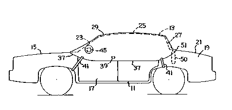
Fig. 1 shows a conventional sedan-type vehicle having
a lower main body portion 11, and an upwardly protruding
cab portion 13. The main body portion has a front hood 15,
side doors 17, and a rear trunk 19; the trunk i8 closed by
a hinged trunk lid 21. Cab portion 13 has a front
windshield 23, roof 25, and rear window 27.
The invention relates more particularly to a flexible
cover 29 adapted for placement over the cab portion of the
vehicle. The cover is preferably formed of a single
weather-resiætant sheet of material 31 formed into a hood-
like configuration. As shown in Fig. 2, the blank sheet is
slit at its four corners, as at 33, after which the slit
edges 35 are sewn together to reconfigure the sheet into a
hollow three-dimensional shape conforming generally to the
surface contours of vehicle cab portion 13.
When the cover is installed on the vehicle, its
peripheral side edge 37 extends along the side surfaces of
the main ~ody portion 11 a slight distance below the
2~1532
in~erface with the cab portion 13. Side surfaces of the
cover extend below the door locks 39 (Fig. 1) to shield
such locks from the weather elements, such as freeze-up.
The cover is held down against the vehicle body by
means of four flexible straps 41, two of which are shown in
Fig. 1. Each strap may be a length of elastomeric material
having V-shaped notches along its side edges to provide a
sinuous strap construction having enhanced resilience and
stretchability. Each strap terminates in a hook 43, that
may be an integral inturned end portion of the strap
material designed to hook around an edge of a wheel well on
the vehicle body.
Figs. 3 and 4 show two different cover constructions
designed to provide clearance around an outside rear view
mirror 45 projecting from a side surface of the vehicle.
Figs. 3 and 4 are views looking in a front-to-rear direc-
tion along the side surface of the vehicle. In the Fig. 3
arrangement, the cover has a hole therethrough; a hollow
fabric sock 47 is sewn to the cover sheet along the edge
area of the hole in the sheet.
Fig. 4 shows an arrangeDent wherein an annular band 49
is sewn to the interior surface of sheet 31 while in an
expanded condition. The band is shown in a contracted
condition (with a smaller diameter), whereby the cover
2~ sheet is bulged outwardly to partially surround the rear
view mirror while keeping the sheet close against the
vehicle side surface.
The structures shown in Figs. 3 and 4 are designed to
~81 532
provide an enclosure around the rear view mirror, while
~eeping sheet 31 relatively close against the vehicle
surface, especially at the lower peripheral edge 37 of the
sheet. The aim is to preclude wind forces from getting
underneath the cover so as to ur.duly stress the cover or
tear it away from the vehicle.
A major feature of the invention is an anchorage
mechanism attached to an interior surface of cover sheet 31
for preventing unauthorized remo~al of the sheet from the
vehicle, e.g. ~y a thief or vandal. The anchorage
mechanism comprises an elongated flexible structure at-
tached to sheet 31 adjacent its rear edge 51 for downward
insertion into the trunk 19 space when lid 21 is in a
raised open condition. After insertion of the anchorage
mechanism into the trunk interior space, trunk lid 21 can
be lowered to a closed position to exert a clamping force
on the anchorage structure. The lid forces the flexible
anchorage structure against the edge of the trunk opening,
such that the anchorage structure is clamped in a relative-
ly fixed position preventing removal of cover sheet 31 fromits installed po~ition on the vehicle.
An air-operated alarm means is attached to the lower
end of the anchorage structure for disposition within the
trunk interior space. The anchorage ~tructure includeæ an
Z5 air-containment chamber means located within the trunk
interior space. Should a thief exert a pulling force on
sheet 31 in order to gain access to the concealed anchorage
~tructure for severing purposes, the air-containment
2~81532
chamber means will be squeezed by the pulling action so
that air is expelled from the chamber means through the
associated air-operated alarm means. Air flowing through
the alarm means produces an audible alarm signal. In the
preferred practice of the invention, the alarm means is a
whistle or small siren (turbine).
The preferred anchorage mechanism is a flexible open-
mouth fabric ~ag 50 attached to the undersurface of cover
sheet 31 adjacent its rear edge 51. Fig. 2 shows the
fabric bag 50 in the flat blank stage prior to being sewn
together into the bag configuration. The bag includes a
first flat major side wall 53, two minor side walls 54, and
two half wall sections 55. When the blank sheet is folded
into a tubular condition, and the confronting edges of the
various side walls are sewn together, there is formed a
three dimensional bag. Edges 57 of the bag constitute the
upper open mouth portion of the bag; end edges 59 of the
bag are sewn together to form the closed bottom of the bag.
Two conventional tubular whistles 61 are adhesively or
otherwise attached to bag wall 53 so as to be in pneumatic
communication with the bag interior space.
The bag is attached to the undersurface of cover sheet
31 by gluing and stitching the upper edge area of bag wall
53 to the sheet along a glue-stick line 63 extending
parallel to rear edge 51 of the sheet. The glue-stick line
is spaced slightly away from edge 51 (two or three inches),
so that when the cover sheet is installed on the vehicle,
the rear edge portion of sheet 31 extends along the upper
2~81532
surface of trunk lid 21; the bag structure extends
downwardly into the trunk interior space, as shown in Fig.
5.
Referring to Fig. 5, there is shown a generally
conventional vehicle construction that fragmentarily
includes rear window 27, a vehicle drip trough structure
65, an elastomeric seal element 67 bordering the trunk
opening, and the upper edge of trunk lid 21. When the lid
is swung upwardly to its open position a clearance space is
created for downward insertion of bag 50 into the trunk
interior space. As the lid is later swung down to its
closed position, the front edge area of the lid deflects
the major bag walls into a pinched condition engaged
against sealing element 67. The bag is thus sealed shut,
trapping air within the bag. The bag acts as an anchorage
device for cover sheet 31.
Should a thief attempt to gain access to the bag for
purpose of severing it from sheet 31 he/she will necessari-
ly have to llft up the rear edge area of the sheet. The
bag structure is disturbed by the action of raising sheet
31, such that the bag tends to be drawn upwardly through
the crack between sealing element 67 and the edge of lid
21. The upper wall portions of the bag are squeezed
together, such that air is expelled d~wnwardly out of the
bag through whistles 61. Air flow through the whistles
produces an audible alarm signal that frightens the would-
be thief away from the vehicle.
Bag structure 50 can be designed to have a relatively
2~8~3~
large volumetric capacity, which is desirable for generat-
ing a prolonged alarm signal. During the entire time that
the would-be thief is attempting to pull cover sheet 31
away from the vehicle, the audible alarm signal continues.
The bag structure can be provided at its lower end with an
enlargement that prevents complete removal of the bag
structure from the trunk interior space. Whistles 61
constitute enlargements for this purpose; additional
enlargements can be incorporated into the bag bottom end if
so desired.
The illustrated anti-theft construction depicted in
Fig. 5 is used in the trunk interior space. Similar anti-
theft structures could be employed within the vehicle
passenger space. Such anti-theft structures would be
inserted through the openings closed by side doors 17,
after which the doors would be closed and locked to retain
the anti-theft anchorage devices within the passenger
space.
Within the broader aspects of the invention, the anti-
theft bag structure 50 and associated alarms 61 can be usedat any joint between a vehicle access opening and
a~sociated closure (door 17 or lid 21). However, the
arrangement depicted in Fiq. 5 is preferred because the
trunk lid can be readily opened and closed after the cover
sheet 31 is installed on the vehicle; only the rear edge
portion of sheet 31 extends across any part of the trunk
lid.
If the anti-theft device were employed in the passenger
11 2081~32
space (through side doors 173 the door would have to be
closed after the cover is in its installed position. This
is somewhat inconvenient in that the cover sheet extends
around or over the upper portion of the door so that the
door has to be moved forcibly against the interior surface
of the cover sheet.
When the invention is employed on a pickup truck or
other vehicle not equipped with a trunk, the anti-theft
mechanism will necessarily be utilized in the passenger
space.
~ ro~ the standpoint of optimal anti-theft protection
for the cover in a passenger car environment, the use of
multiple anchorage mechanisms would be the most preferred
system. For example, one anchorage mechanism would be
disposed within the trunk as shown in Fig. 5, and a second
anchorage mechanism could be disposed within the passenger
space along an inside edge of an access door 17. Fig. 7
fragmentarily shows a second anchorage mechanism attached
to the underside of cover sheet 31 for disposition along an
upper inside edge or vertical edge of a door 17. The
anchorage mechanism comprises a hollow sealed pillow or
balloon structure 70 formed of a reasonably strong non-
porous fabric. The pillow structure is air-filled.
Pillow structure 70 has an elongated flexible neck
structure 72 attached to ths undersurface of cover sheet
31. When the balloon structure is inserted into the
passenger space and the door 17 is closed ~and locked) the
pillow structure provides added anti-theft protection
2~81532
12
(supplementing the protection offered by bag 50 and alarm
mechanisms 61). The air-filled pillow structure can be
relatively small, e.g. only about five inches in diameter,
while still providing the desired protection. An external
pulling action on neck structure 72 pressurizes the pillow
structure and thereby increases the resistance to the pull-
out force.
The principal feature of the invention is the bag
structure 50 and associated alarm means 61. The use of a
bag structure as an air-containment chamber means is
advantageous in that a relatively large air-containment
chamber can be formed. Also, the bag can be used as a
storage device for sheet 31 when the sheet is detached from
the vehicle. Sheet 31 can be folded into a relatively
compact bundle and then stuffed into the bag.
If it is not desired to use bag 50 as a cover sheet
storage device, the upper ends of the bag walls can be
permanently sealed shut, in the Fig. 5 configuration to
form a closed air-containment chamber means. A check valve
would be provided in the chamber wall to admit air into the
chamber.
The drawings necessarily show a specific embodiment of
the invention. However, it will be appreciated that the
invention can be practiced in various forms and configura-
tions.
Therefore I claim: